patent · US4475538
Window for solar receiver for a solar-powered hot gas engine
9 October 1984
Page 1 — bibliographic record
United States Patent (19) 11) Patent Number: 4,475,538 Percival et al. 45) Date of Patent: Oct. 9, 1984
54 WINDOW FOR SOLAR RECEIVER FOR A
SOLAR-POWERED HOT GAS ENGINE OTHER PUBLICATIONS (75) Inventors: Worth H. Percival, Oakton; David N. “Dish Stirling Solar Receiver Program Final Report', Wells, Arlington, both of Va. Doc. No. ER 79917-3, Dec. 15, 1980, Including pp. i-ix,
73) Assignee: United Stirling AB, Malmo, Sweden Dwg. No. 79917001.
21 Appl. No.: 556,568 Chubb, "Solar Energy', vol. 23, pp. 217-221, 1979, FIGS. 1 and 2.
Primary Examiner-Daniel J. O'Connor 51) Int. Cli................................................. F24J 3/02 Attorney, Agent, or Firm-Finnegan, Henderson, 52) U.S. C. .................................... 126/439; 126/441; Farabow, Garrett & Dunner
(58) Field of Search ............... 126/417,438, 439, 440, 57) ABSTRACT 126/441, 442, 449, 450; 60/641.8, 641.15 The solar receiver for use e.g. with a solar-powered 56) References Cited Stirling-type hot gas engine includes an internally
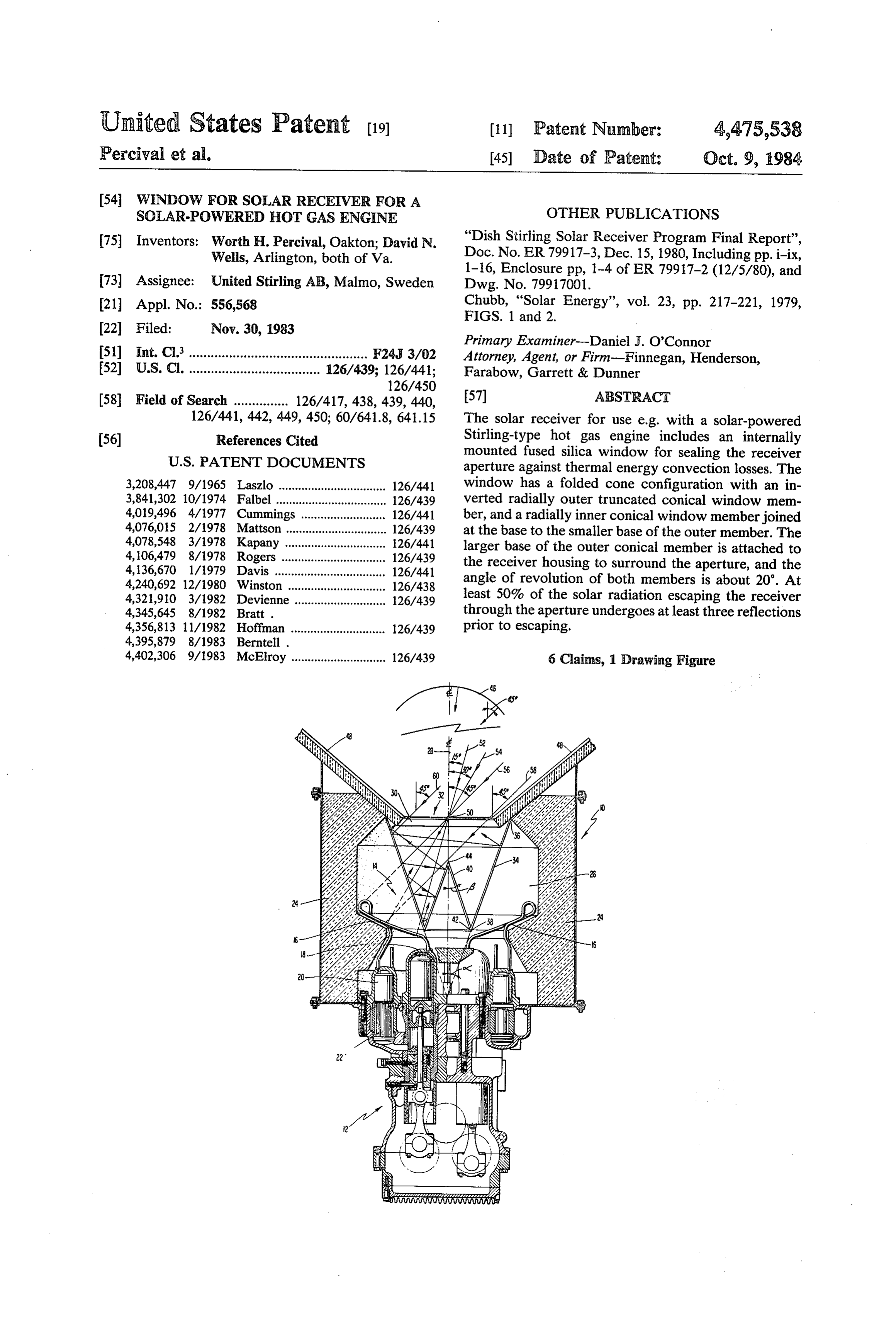
mounted fused silica window for sealing the receiver aperture against thermal energy convection losses. The 3,208,447 9/1965 Laszlo ................................. 126/441 window has a folded cone configuration with an in 3,841,302 10/1974 Fallbel .................................. 126/439 verted radially outer truncated conical window mem 4,019,496 4/1977 Cummings .. ... 126/441 ber, and a radially inner conical window member joined 4,076,015 2/1978 Mattson ............................... 126/439 at the base to the smaller base of the outer member. The 4,078,548 3/1978 Kapany ............................... 126/441 larger base of the outer conical member is attached to 4,106,479 8/1978 Rogers ................................ 126/439 the receiver housing to surround the aperture, and the 4,136,670 1/1979 Davis .................................. 126/441 4,240,692 12/1980 Winston .............................. 126/438 angle of revolution of both members is about 20. At 4,321,910 3/1982 Devienne ............................ 126/439 least 50% of the solar radiation escaping the receiver 4,345,645 8/1982 Bratt . through the aperture undergoes at least three reflections 4,356,813 11/1982 Hoffman ............................. 126/439 prior to escaping.
4,402,306 9/1983 McElroy ............................. 126/439 6 (Claims, 1 Drawing Figure
Page 2
Drawing sheet — no readable text.
Page 3
circular conical shell and having the shell edge forming
WER3CW FOR SOLAR RECEIVER FOR A the larger cone base positioned adjacent the housing to SOEAREPOWERED HOT GAS ENGINE surround the aperture and having the shell edge form ing the smaller cone base extending within the cavity,
BACKGROUND the axis of revolution of the outer conical shell being 1. Field of the Invention colinear with the centerline of the receiver, and an inner This invention relates to solar receivers for solar window member in the shape of a right circular conical powered hot gas engines. shell positioned within the outer conical shell and hav 2. Description of the Prior Art ing the shell edge forming the inner shell conical base Solar receivers typically include an insulated housing 10 connected to the outershell smaller base edge and hav defining a receiver cavity and an aperture in the housing ing the vertex of the inner conical shell extending to admit solar radiation for conversion to thermal (heat) toward the aperture, the axis of revolution of the inner energy inside the cavity, for subsequent utilization such conical shell also being colinear with the centerline of as by a heat engine of the hot gas (Stirling) type. the receiver, and wherein the dimensions of the inner Significant heat losses may occur from convection 15 and outer conical shell window members are selected in effects with open-aperture solar Stirling receivers. For relation to the dimensions of the aperture and cavity to example, for a 22 cm diameter aperture, 20 C. air enter provide an effect which results in a plurality of the ing with a velocity of 1 m/s flowing into of the aper reflections remaining within the cavity, the solar radia ture heated to 520' C. and flowing out the remaining 20 tion initially intercepted but reflected by either of the area of aperture will carry away about 7.75 kW of ther inner and outer window members being substantially mal energy. Typical average wind speed of 5 m/s for transmitted into the cavity. Preferably, the dimensions the U.S. may cause serious problems in reaching current of the inner and outer conical shell window members receiver efficiency estimates of 85%. are selected in relation to the dimensions of the aperture Quartz (fused silica) windows mounted in the plane of 25 and cavity to provide at least three reflections within the aperture have been suggested as possibly providing the cavity for at least 50% of the solar radiation initially a method of reducing convection losses, as well as heat intercepted but reflected by either of the inner and outer (infra-red) radiation losses. The FIGURE is a schematic window members before any reflected solar radiation of a solar-powered Stirling hot gas engine having a can pass back through the aperture and escape the re receiver including an insulated housing surrounding the ceiver.
hot gas engine heater head with a quartz window 30 Preferably, the conical angles of the inner conical mounted in the plane of the aperture. A problem with quartz windows, unfortunately, is reflectivity. For in shell and the outer conical shell are about equal in mag stance, baseline 89.2 m2 parabolic dish collector-con membersand nitude, the inner and outer conical shell window are formed from fused silica.
centrator with 90% reflectance at 0.85 kW/m2 insola
It is also preferred that the solar radiation initially tion would be delivering 68.2 kW of radiant energy to 35 incident the receiver. For a nominal 10% reflective flat quartz bolic dish-typeon the receiver has been reflected from a para window, the reflectivity would cause a 6.8 kW loss, providing reflected solar collector-concentrator, the dish which would be sacrificed before any gain from saved from the receiver centerline,radiation at angles up to about 45 convection losses would be realized. and wherein the conical It has also been suggested by Francia and, later, by angles of the inner and outer conical shells are each Chubb to use an assembly of transparent, open-ended about 20.
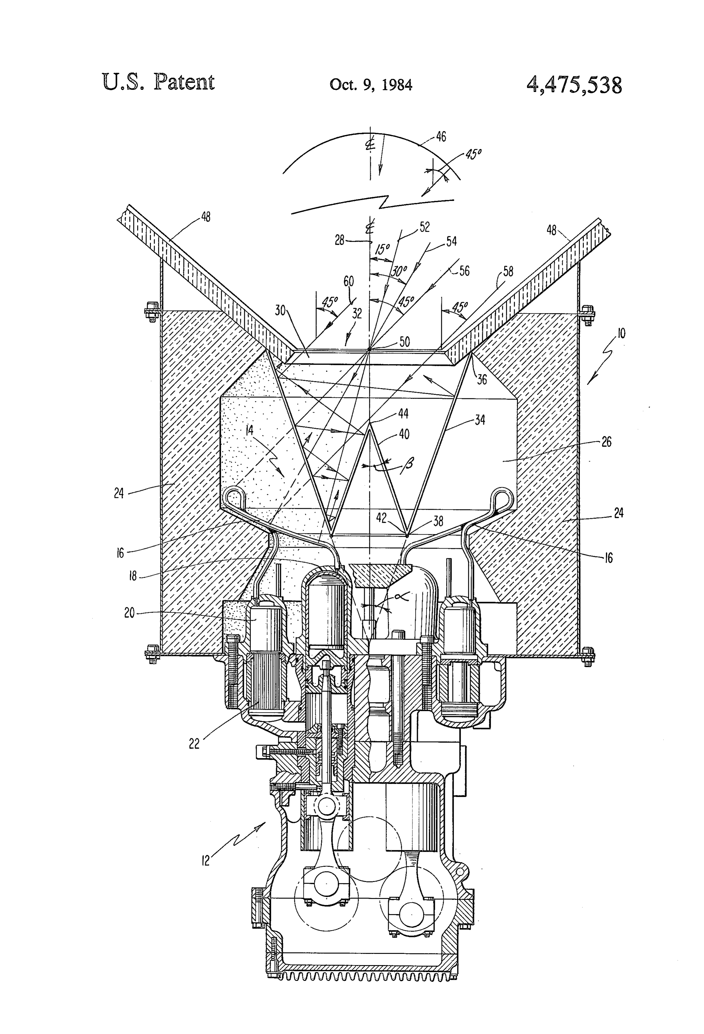
tubes oriented perpendicular to the aperture plane to fill The accompanying drawing which is incorporated the aperture of a solar receiver (see e.g. Chubb, "Solar in, and constitutes a part of, this specification illustrates Energy” vol. 23, pp. 217-221, 1979, FIGS. 1 and 2). one embodiment of the invention and, together with the Solar radiation incident on the ends of the tubes at an 45 description, serves to explain the principles of the in gles to the tube axes would be reflected down the tube vention.
and into the cavity. However, this arrangement suffers BRIEF DESCRIPTION OF THE DRAWING from back reflection from the ends of the tubes which can constitute a significant fraction of the aperture pla The FIGURE is a schematic view of an improved nar area. Also, the arrangement does not provide a true 50 solar receiver having a window used in conjunction barrier against ambient wind and convection currents, with a hot gas engine and made in accordance with the and can be complicated and expensive to construct. present invention.
Reference will now be made in detail to the present
SJAMARY OF THE INVENTION preferred embodiment of the invention, an example of In accordance with the present invention, as embod 55 which is illustrated in the aforesaid drawing. ied and broadly described herein, an improved solar DESCRIPTION OF THE PREFERRED receiver for conversion of solar radiation to thermal EMBODIMENT energy is provided of the type including a heat ex changer for the transfer of heat out of the receiver, an The FIGURE shows a solar receiver, designated insulated housing forming a cavity surrounding the heat 60 generally by the numeral 10, which is used to convert exchanger, and an aperture in the housing to allow the solar radiation into thermal energy to be utilized, for influx of solar radiation, the housing having an axis instance, by a hot gas engine, such as engine 12. Hot gas centerline of the receiver and the center of the aperture engine 12 is of the double acting Stirling type wherein a and the center of the heat exchanger both being located plurality of working gas charges are confined in vari on the centerline, wherein the improvement comprises a 65 able volume chambers between pairs of cylinders hav window for intercepting solar radiation passing through ing pistons reciprocating out of phase. Engine 12 in the aperture, the window including an outer window cludes heater head 14 which further includes a plurality member in the shape of an inverted truncated right of individual heater pipes 16 which carry the working
Page 4
gas charges between a cylinder such as cylinder 18 to a respective edges, which attachment also should provide respective regenerator-cooler assembly such as regener for sealing against thermal energy convection losses and ator-cooler assembly 20, 22 and to another cylinder (not provide the required amount of integrity. Again, such shown). Heater head 14 functions as the heat exchanger means of attachment, for instance by fusing, the respec for receiver 10 to transfer heat out of the receiver and to 5 tive members would be within the skill of one working the working gas charges of engine 2. Heater pipes 16 in the art.
are arrayed in a conical shape. Detailed descriptions of An important feature of the window made in accor such heater head assemblies are presented, e.g., in U.S. dance with the present invention is that a large fraction Pat. Nos. 4,345,645 and 4,395,879. of the rays incident on the receiver through aperture 30 The improved solar receiver of the present invention 10 from a typical collector-concentrator, such as parabolic is not restricted to use with a hot gas engine, or to use dish reflector 46 shown schematically in the FIGURE, with a hot gas engine of the Stirling type, as other appa and not transmitted to the portion of cavity 26 behind ratus for utilizing the converted thermal energy can be window 32, would undergo at least 3 reflections before employed and other engine types (e.g. Rankine, Bray passing back through aperture 30 and escaping the re ton, etc.) can be used. 15 ceiver. Typical collector-concentrators generally re As depicted in the FIGURE, receiver 10 includes a radiate over about a 90° angle, that is 45 to either side generally cylindrical insulated housing 24 surrounding of the dish centerline. Receiver housings often have a heater head 14 and defining receiver cavity 26 and re conical wall surrounding the aperture, such as aperture ceiver centerline 28. An aperture such as circular aper cone 48 on housing 24 shown in the FIGURE. In the ture 30 is provided in cylindrical housing 24 at one axial 20 FIGURE, parabolic dish reflector 46 is shown at a end to admit solar radiation such as from a parabolic much reduced scale in size and spacing relative to the dish collector-concentrator (not shown), and heater scale and location of engine 12 and receiver 10. head 14 is located at the opposite axial end of housing As embodied herein, radially outer shell 34 of win 24. Aperture 3 is shown coaxial with the conical heater dow 32 has a conical angle (angle of revolution) of head 4 and cylindrical housing 24, and having a diame- 25 about 20 (angle a drawn on the dotted extensions of ter smaller than the inside diameter of cylindrical hous member 34), and radially inner conical shell 40 also has ing 24. a conical angle of about 20 (angle (3) giving rise to a In accordance with the present invention, the im "folded cone' window. The height of the outer conical proved receiver of this invention is provided with a member 34 is about 10 inches, and the height of the window for intercepting solar radiation passing through 30 inner conical member 40 is about 4 inches, while the the aperture. The window of this invention specifically diameter of aperture 30 is about 8 inches. Fused silica or includes an outer window member in the shape of an an equivalent transparent high temperature material inverted, truncated, conical shell positioned wholly (e.g. Vicor, made by the Corning Glass Company) can within the receiver cavity. As embodied herein, and be used to fabricate window members 34 and 40. with continued reference to the FIGURE, a window 35 As can be seen from the FIGURE, for a perfect designated generally by the numeral 32 is shown com point-focusing collector-concentrator wherein all the pletely located within cavity 26 and includes a radially rays pass through point 50 in aperture 30, all rays except outer window member 34 in the shape of an inverted perhaps the rays normally incident on the vertex 44 of truncated conical shell with the cone edge 36 forming inner window member 40 would undergo at least three the larger cone base connected to housing 24 to sur- 40 reflections before passing back out of aperture 30. This round aperture 30. Shell edge 38 which forms, the phenomenon is shown schematically by rays 52, 54, and smaller cone base is positioned closely adjacent heater 56 in the FIGURE. At each reflection, a portion of the head 14. Cone edge 36 can be attached to housing 24 in incident reflected ray is transmitted through the respec a variety of ways all within the capability of one skilled tive window member while a smaller fraction is rere in the art, but the manner of attachment should provide 45 flected. Thus, the fraction of the radiant energy actually for sealing against thermal energy convection losses out lost decreases geometrically with the number of reflec of cavity 26 through the aperture past cone edge 36 and tions.
also preferably should accommodate any differences in For example, the transmission of solar radiation for thermal expansion rates of the window material and the rays normal to a window surface, and up to about 40 housing and also, preferably, provide some degree of 50 from the normal, is about 90%. For steeper angles, the protection for the window against vibration caused by transmittance becomes lower; at 60 it is about 83%. By the engine 12 acting through housing 24. For example, providing a window in which the solar radiation under a clip-type suspension could be employed with a sealing goes at least three reflections, as illustrated, the losses ring. can be significantly reduced. For three reflections the Further in accordance with the present invention, the 55 losses become (1-0.9)3X 100, or about 0.1% of the window includes an inner window member in the shape solar radiation incident from the collector-concentra of a conical shell and positioned within the outer coni to.
cal shell, also wholly within the receiver cavity. As However, actual parabolic dish collector-concentra embodied herein, and with continued reference to the tor systems rarely achieve perfect point-focusing due to FIGURE, window 32 includes a radially inner window 60 a number of reasons, including small distortions in the member 40 in the shape of a conical shell having cone parabolic reflecting surface, specular reflections from edge 42 forming the base of the cone and the cone ver an imperfect reflecting surface, etc. This imperfect fo tex 44. Inner window member 40 is oriented and posi cusing can cause rays emanating from a portion of the tioned so that cone edge 42 is connected to the outer parabolic reflector 46 to enter cavity 26 near the edges conical shell edge 38 with the cone vertex 44 directed 65 of aperture 30. In the FIGURE, rays 58 and 60 are toward aperture 30. The smaller base of outer cone presented to illustrate this phenomenon, showing rays member 34 and the base of inner cone member 40 have emanating from the outer 45 portion of parabolic re the same diameter to facilitate the attachment of the flector 46. As depicted schematically in the FIGURE,
Page 5
the window of the present invention provides for three of said outer conical shell being colinear with the reflections of ray 58 but ray 60 is reflected only twice centerline of the receiver, and before passing back through aperture 30. (ii) an inner window member in the shape of a conical In the improved receiver shown in the FIGURE, the shell positioned within said outer conical shell and dimensions of outer conical shell 34 and inner conical having the shell edge forming the inner shell coni shell 40 are chosen so that inner conical shell vertex 44 cal base connected to the outer shell smaller base is just below the most oblique incoming ray (ray 58), edge and having the vertex of the inner conical and so that the cone edges 38 and 42 are adjacent heater shell extending toward the aperture, the axis of head 14 with a clearance sufficient to prevent vibration revolution of said inner conical shell also being damage. 10 colinear with the centerline of the receiver, and The window of the present invention thus cannot wherein the dimensions of said inner and outer coni insure a triple reflection of all the incoming solar radia cal shell window members are selected in relation tion, as a small fraction of the incoming radiation will to the dimensions of the aperture and cavity to undergo only two reflections before passing out of the provide at least three reflections within the cavity receiver. However, it is believed that well over 50% of 15 for at least 50% of the solar radiation initially inter the radiation passing back through aperture 30 and cepted but reflected by either of said inner and escaping the receiver will have undergone at least three outer window members before any reflected solar reflections prior to its escape. Consequently, the re radiation can pass back through the aperture and ceiver of the present invention having the window as described above should result in significant increases in 20 2. escape
The the receiver.
improved solar receiver as in claim 1 wherein the overall receiver efficiency over conventional solar the conical angles of said inner conical shell window receivers. member and said outer conical shell window member It will be apparent to those skilled in the art that are about equal in magnitude. various modifications and variations can be made in the improved solar receivers of the present invention with 25 the3.conical
The improved solar receiver as in claim 2 wherein out departing from the scope or spirit of the present outer conicalangles shell of said inner conical shell and said are about 20.
invention.
What is claimed is: 4. The improved solar receiver as in claim 1 wherein 1. An improved solar receiver for conversion of solar said inner and outer conical shell window members are radiation to thermal energy of the type including a heat 30 formed from transparent fused silica. 5. The improved solar receiver as in claim a wherein exchanger for the transfer of heat out of the receiver, an insulated housing forming cavity surrounding the heat the dimensions of said inner conical shell window mem exchanger and an aperture in the housing to allow the ber are such that the cone vertex lies just below the path influx of solar radiation, the housing having an axis of the most oblique solar ray passing through the aper constituting the centerline of the receiver and the center 35 ture, relative to the receiver centerline. of the aperture and the center of the heat exchanger 6. The improved solar receiver as in claim 1 wherein both being located on the centerline, the improvement the solar radiation initially incident on the receiver has comprising been reflected from a parabolic dish-type collector-con a window for intercepting solar radiation passing centrator, the dish providing reflected radiation at an through the aperture, said window including gles up to about 45° from the receiver centerline; the (i) an outer window member in the shape of an in conical angles of said inner and outer conical shell win verted truncated conical shell and having the shell dow members are each about 20; the heights of said edge forming the larger cone base positioned adja inner and outer conical shell window members are cent the housing to surround the aperture and hav about 10 inches and 4 inches, respectively; and the di ing the shell edge forming the smaller cone base 45 ameter of the aperture is about
8 inches, extending within the cavity, the axis of revolution
Provenance
- Collection
- Cited prior art
- Original PDF
- patentimages.storage.googleapis.com →
- Filed
- 1983-11-30
- Pages
- 5
- Method
- pdftotext (the PDF's own text layer) + pdftoppm 300dpi page scans
- Source
- Google Patents bibliographic record
- Granted
- 1984-10-09
- Inventors
- Worth H. Percival; David N. Wells; United Stirling AB and Co
- Transcribed from
- patentimages.storage.googleapis.com →