patent · US4745906
Passive heat transfer device
24 May 1988
Page 1 — bibliographic record
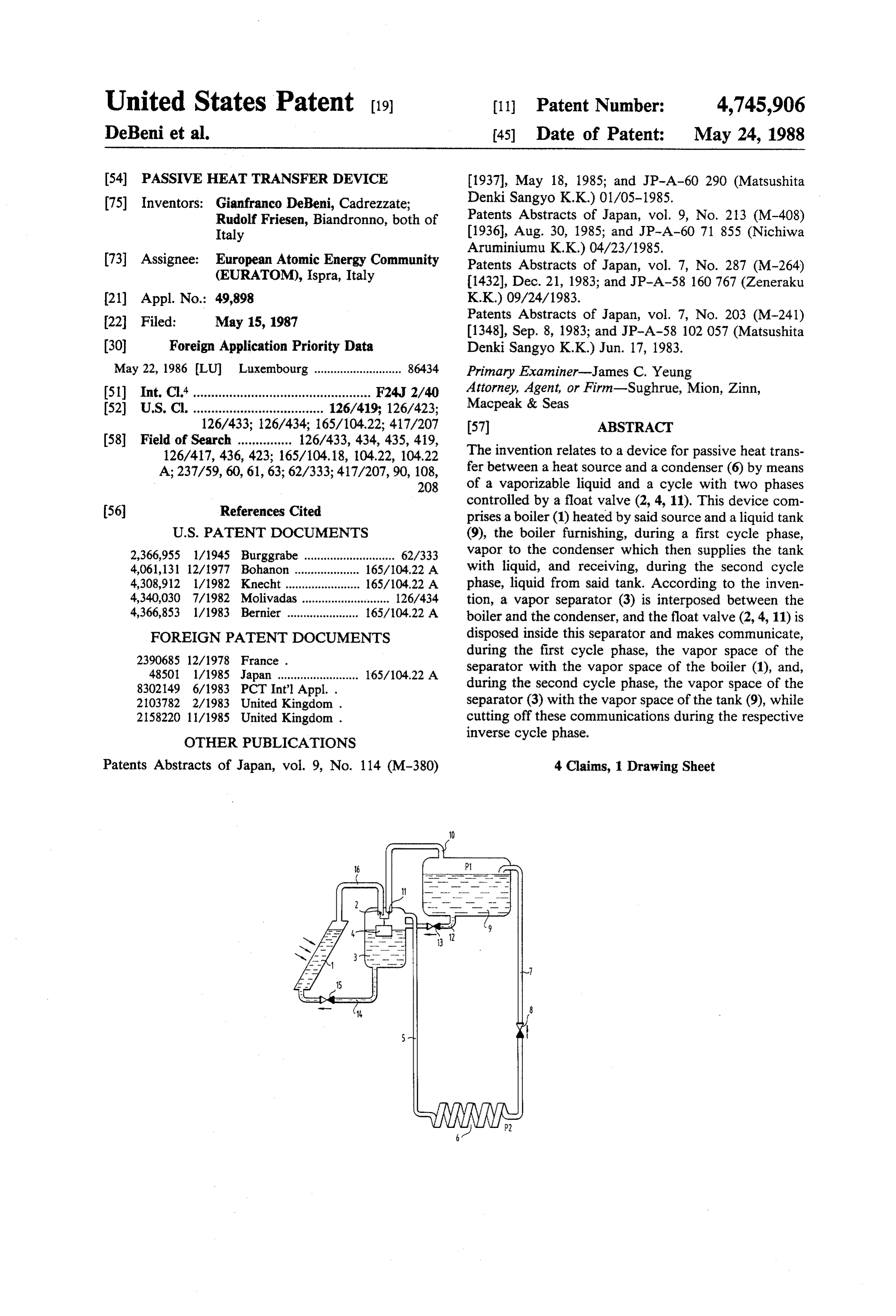
United States Patent (19) 11 Patent Number: 4,745,906 DeBeni et al. (45) Date of Patent: May 24, 1988 (54) PASSIVE HEAT TRANSFER DEVICE (1937), May 18, 1985; and JP-A-60 290 (Matsushita (75) Inventors: Gianfranco DeBeni, Cadrezzate; Denki Sangyo K.K.) 01/05-1985. Rudolf Friesen, Biandronno, both of Patents Abstracts of Japan, vol. 9, No. 213 (M-408) Italy (1936), Aug. 30, 1985; and JP-A-60 71 855 (Nichiwa 73 Assignee: European Atomic Energy Community Aruminiumu K.K.) 04/23/1985. (EURATOM), Ispra, Italy Patents Abstracts of Japan, vol. 7, No. 287 (M-264)
(21) Appl. No.: 49,898 K.K.) 09/24/1983.
(22 Filed: May 15, 1987 Patents Abstracts of Japan, vol. 7, No. 203 (M-241)
(30) Foreign Application Priority Data Denki Sangyo K.K.) Jun. 17, 1983. May 22, 1986 (LU) Luxembourg ........................... 86434 Primary Examiner-James C. Yeung 51) Int. Cl." ................................................. F24J 2/40 Attorney, Agent, or Firm-Sughrue, Mion, Zinn, 52 U.S.C. .................................... 126/419; 126/423; Macpeak & Seas 126/433; 126/434; 165/104.22; 417/207 57) ABSTRACT
126/417, 436, 423; 165/104.18, 104.22, 104.22 The invention relates to a device for passive heat trans A; 237/59, 60, 61, 63; 62/333; 417/207,90, 108, fer between a heat source and a condenser (6) by means 208 of a vaporizable liquid and a cycle with two phases 56 References Cited controlled by a float valve (2, 4, 11). This device com prises a boiler (1) heated by said source and a liquid tank
2,366,955 1/1945 Burggrabe ............................ 62/333 vapor to the condenser which then supplies the tank 4,061,131 12/1977 Bohanon .... . . 165/104.22 A with liquid, and receiving, during the second cycle 4,308,912 1/1982 Knecht ....................... 165/104.22 A phase, liquid from said tank. According to the inven 4,340,030 7/1982 Molivadas ........................... 126/434 tion, a vapor separator (3) is interposed between the 4,366,853 1/1983 Bernier ...................... 165/104.22 A boiler and the condenser, and the float valve (2, 4, 11) is FOREIGN PATENT DOCUMENTS disposed inside this separator and makes communicate,
during the first cycle phase, the vapor space of the 48501 1/1985 Japan ......................... 165/104.22 A separator with the vapor space of the boiler (1), and, 8302149 6/1983 PCT Int'l Appl. . during the second cycle phase, the vapor space of the 2103782 2/1983 United Kingdom . separator (3) with the vapor space of the tank (9), while 2158220 11/1985 United Kingdom . cutting off these communications during the respective
OTHER PUBLICATIONS
inverse cycle phase.
Patents Abstracts of Japan, vol. 9, No. 114 (M-380) 4 Claims, 1 Drawing Sheet
Page 2
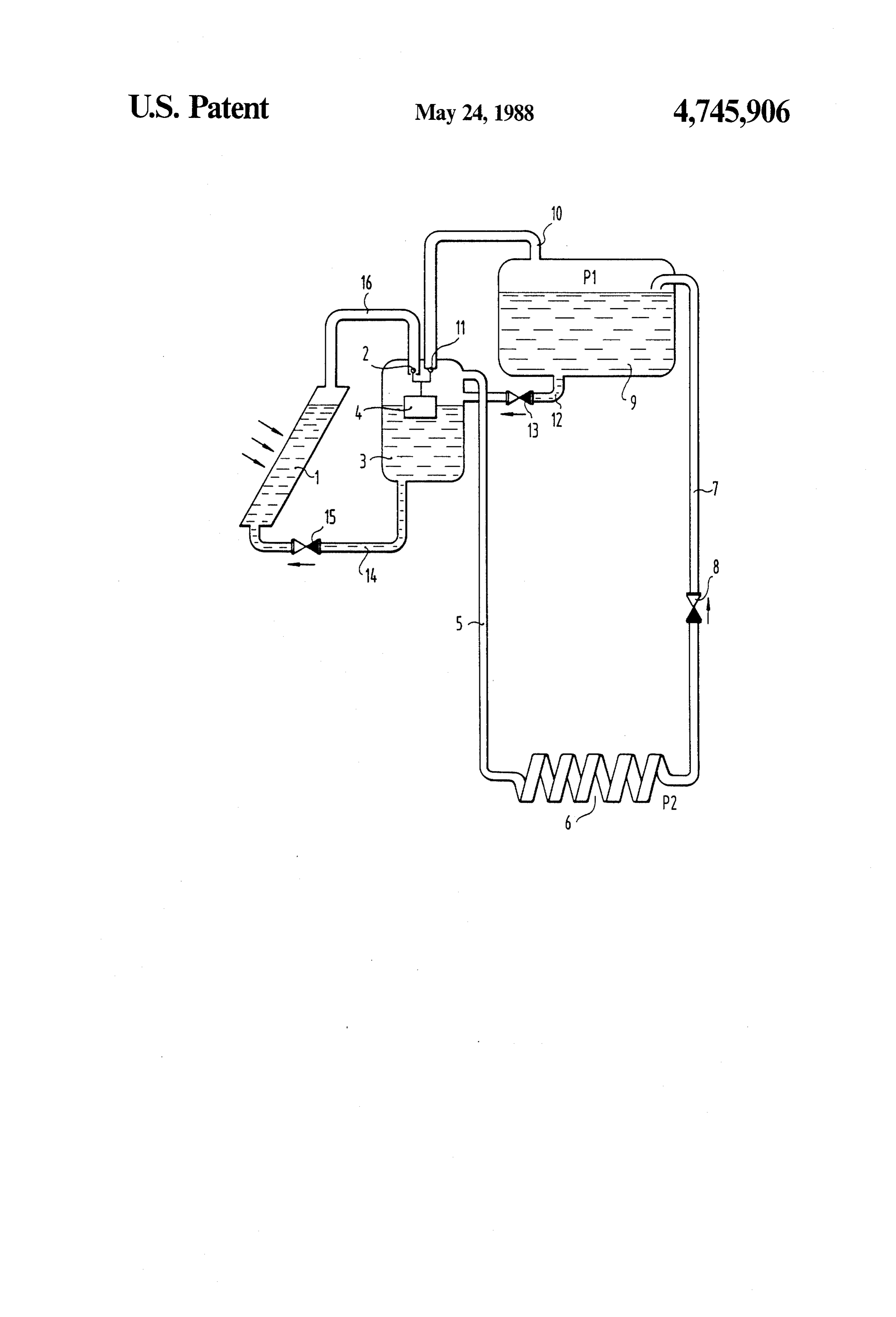
Drawing sheet — no readable text.
Page 3
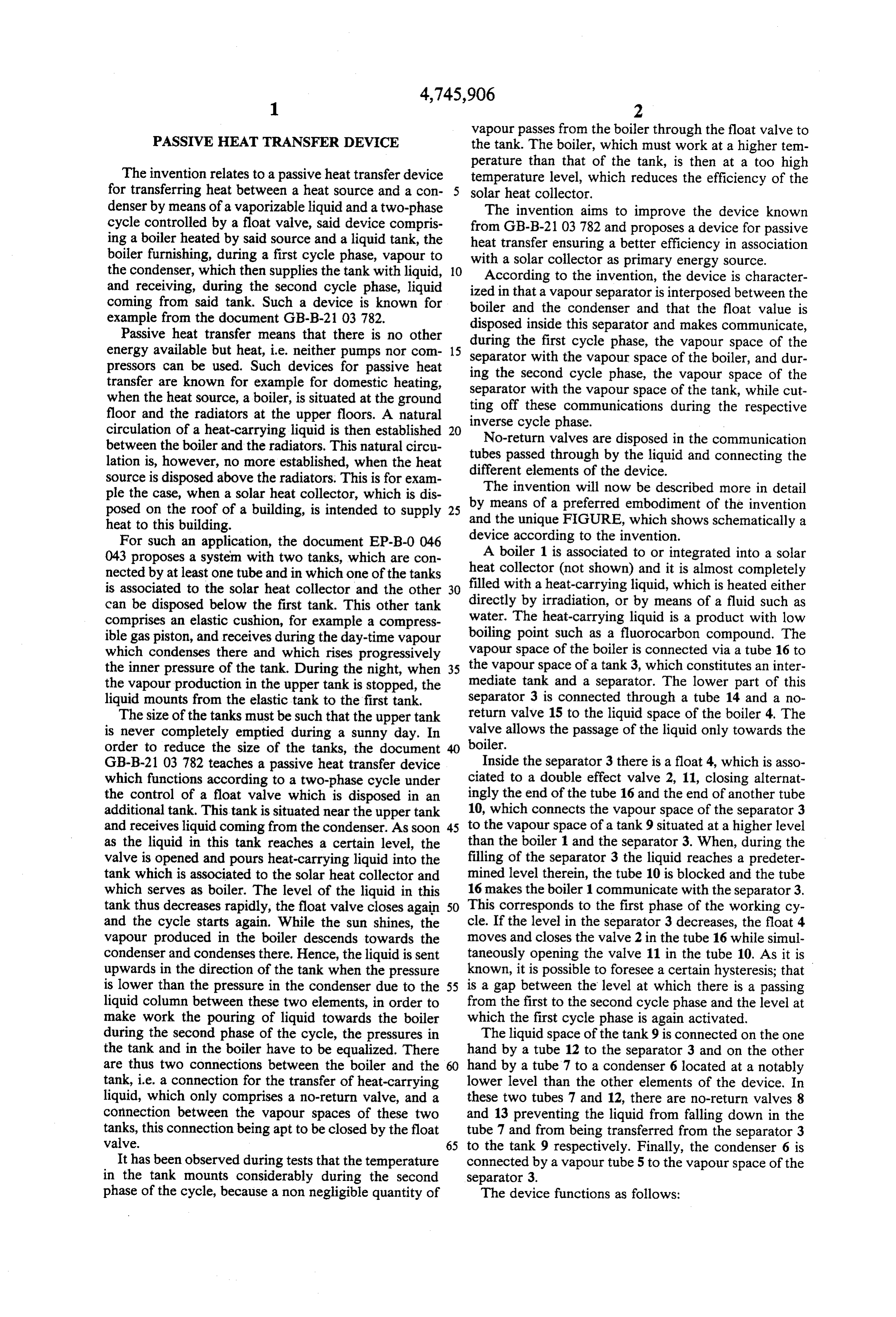
vapour passes from the boiler through the float valve to
PASSIVE HEAT TRANSFER DEVICE the tank. The boiler, which must work at a higher tem perature than that of the tank, is then at a too high
The invention relates to a passive heat transfer device temperature level, which reduces the efficiency of the for transferring heat between a heat source and a con solar heat collector.
denser by means of a vaporizable liquid and a two-phase The invention aims to improve the device known cycle controlled by a float valve, said device compris from GB-B-2103 782 and proposes a device for passive ing a boiler heated by said source and a liquid tank, the boiler furnishing, during a first cycle phase, vapour to heat with transfer ensuring a better efficiency in association a solar collector as primary energy source.
the condenser, which then supplies the tank with liquid, O According to the invention, the device is character and receiving, during the second cycle phase, liquid ized in that a vapour separator is interposed between the coming from said tank. Such a device is known for boiler and the condenser and that the float value is example from the document GB-B-2103 782. disposed inside this separator and makes communicate, Passive heat transfer means that there is no other during the first cycle phase, the vapour space of the energy available but heat, i.e. neither pumps nor com 15 separator with the vapour space of the boiler, and dur pressors can be used. Such devices for passive heat ing the second cycle phase, the vapour space of the transfer are known for example for domestic heating, separator with the vapour space of the tank, while cut when the heat source, a boiler, is situated at the ground ting off these communications during the respective floor and the radiators at the upper floors. A natural circulation of a heat-carrying liquid is then established 20 inverse cycle phase.
No-return valves are disposed in the communication between the boiler and the radiators. This natural circu lation is, however, no more established, when the heat tubes passed through by the liquid and connecting the different elements of the device.
source is disposed above the radiators. This is for exam ple the case, when a solar heat collector, which is dis byThe invention will now be described more in detail means of a preferred embodiment of the invention posed on the roof of a building, is intended to supply 25 and the unique FIGURE, which shows schematically a heat to this building.
For such an application, the document EP-B-0046 device according to the invention. 043 proposes a system with two tanks, which are con A boiler 1 is associated to or integrated into a solar nected by at least one tube and in which one of the tanks heat collector (not shown) and it is almost completely is associated to the solar heat collector and the other 30 filled with a heat-carrying liquid, which is heated either can be disposed below the first tank. This other tank directly by irradiation, or by means of a fluid such as comprises an elastic cushion, for example a compress water. The heat-carrying liquid is a product with low ible gas piston, and receives during the day-time vapour boiling point such as a fluorocarbon compound. The which condenses there and which rises progressively vapour space of the boiler is connected via a tube 16 to the inner pressure of the tank. During the night, when 35 the vapour space of a tank 3, which constitutes an inter the vapour production in the upper tank is stopped, the mediate tank and a separator. The lower part of this liquid mounts from the elastic tank to the first tank. separator 3 is connected through a tube 14 and a no The size of the tanks must be such that the upper tank return valve 15 to the liquid space of the boiler 4. The is never completely emptied during a sunny day. In valve allows the passage of the liquid only towards the order to reduce the size of the tanks, the document boiler.
GB-B-2103 782 teaches a passive heat transfer device Inside the separator 3 there is a float 4, which is asso which functions according to a two-phase cycle under ciated to a double effect valve 2, 11, closing alternat the control of a float valve which is disposed in an ingly the end of the tube 16 and the end of another tube additional tank. This tank is situated near the upper tank 10, which connects the vapour space of the separator 3 and receives liquid coming from the condenser. As soon 45 to the vapour space of a tank 9 situated at a higher level as the liquid in this tank reaches a certain level, the than the boiler 1 and the separator 3. When, during the valve is opened and pours heat-carrying liquid into the filling of the separator 3 the liquid reaches a predeter tank which is associated to the solar heat collector and mined level therein, the tube 10 is blocked and the tube which serves as boiler. The level of the liquid in this 16 makes the boiler 1 communicate with the separator 3. tank thus decreases rapidly, the float valve closes again 50 This corresponds to the first phase of the working cy and the cycle starts again. While the sun shines, the cle. If the level in the separator 3 decreases, the float 4 vapour produced in the boiler descends towards the moves and closes the valve 2 in the tube 16 while simul condenser and condenses there. Hence, the liquid is sent taneously opening the valve 11 in the tube 10. As it is upwards in the direction of the tank when the pressure known, it is possible to foresee a certain hysteresis; that is lower than the pressure in the condenser due to the 55 is a gap between the level at which there is a passing liquid column between these two elements, in order to from the first to the second cycle phase and the level at make work the pouring of liquid towards the boiler which the first cycle phase is again activated. during the second phase of the cycle, the pressures in The liquid space of the tank 9 is connected on the one the tank and in the boiler have to be equalized. There hand by a tube 12 to the separator 3 and on the other are thus two connections between the boiler and the hand by a tube 7 to a condenser 6 located at a notably tank, i.e. a connection for the transfer of heat-carrying lower level than the other elements of the device. In liquid, which only comprises a no-return valve, and a these two tubes 7 and 12, there are no-return valves 8 connection between the vapour spaces of these two and 13 preventing the liquid from falling down in the tanks, this connection being apt to be closed by the float tube 7 and from being transferred from the separator 3 valve. 65 to the tank 9 respectively. Finally, the condenser 6 is It has been observed during tests that the temperature connected by a vapour tube 5 to the vapour space of the in the tank mounts considerably during the second separator 3.
phase of the cycle, because a non negligible quantity of The device functions as follows:
Page 4
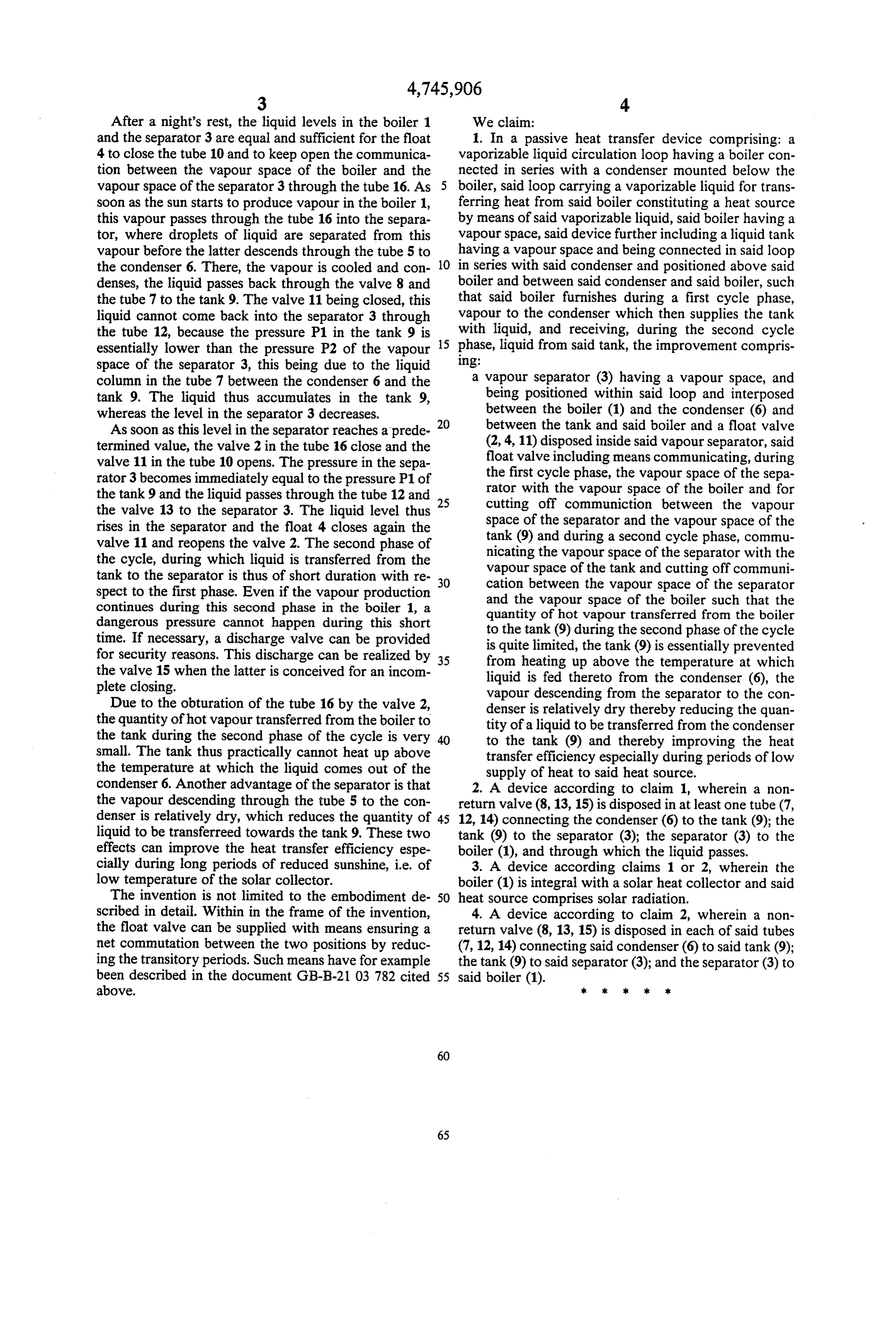
After a night's rest, the liquid levels in the boiler 1 We claim:
and the separator 3 are equal and sufficient for the float 1. In a passive heat transfer device comprising: a 4 to close the tube 10 and to keep open the communica vaporizable liquid circulation loop having a boiler con tion between the vapour space of the boiler and the nected in series with a condenser mounted below the vapour space of the separator 3 through the tube 16. As 5 boiler, said loop carrying a vaporizable liquid for trans soon as the sun starts to produce vapour in the boiler 1, ferring heat from said boiler constituting a heat source this vapour passes through the tube 16 into the separa by means of said vaporizable liquid, said boiler having a tor, where droplets of liquid are separated from this vapour space, said device further including a liquid tank vapour before the latter descends through the tube 5 to having a vapour space and being connected in said loop the condenser 6. There, the vapour is cooled and con 10 in series with said condenser and positioned above said denses, the liquid passes back through the valve 8 and boiler and between said condenser and said boiler, such the tube 7 to the tank 9. The valve 11 being closed, this that said boiler furnishes during a first cycle phase, liquid cannot come back into the separator 3 through vapour to the condenser which then supplies the tank the tube 12, because the pressure P1 in the tank 9 is 15 with liquid, and receiving, during the second cycle essentially lower than the pressure P2 of the vapour phase, liquid from said tank, the improvement compris space of the separator 3, this being due to the liquid Ing:
column in the tube 7 between the condenser 6 and the a vapour separator (3) having a vapour space, and tank 9. The liquid thus accumulates in the tank 9, being positioned within said loop and interposed whereas the level in the separator 3 decreases. between the boiler (1) and the condenser (6) and As soon as this level in the separator reaches a prede 20 between the tank and said boiler and a float valve termined value, the valve 2 in the tube 16 close and the (2, 4, 11) disposed inside said vapour separator, said valve 11 in the tube 10 opens. The pressure in the sepa float valve including means communicating, during rator 3 becomes immediately equal to the pressure P1 of the first cycle phase, the vapour space of the sepa the tank 9 and the liquid passes through the tube 12 and 25 rator with the vapour space of the boiler and for the valve 13 to the separator 3. The liquid level thus cutting off communiction between the vapour rises in the separator and the float 4 closes again the space of the separator and the vapour space of the valve 11 and reopens the valve 2. The second phase of tank (9) and during a second cycle phase, commu the cycle, during which liquid is transferred from the nicating the vapour space of the separator with the tank to the separator is thus of short duration with re vapour space of the tank and cutting off communi spect to the first phase. Even if the vapour production 30 cation between the vapour space of the separator continues during this second phase in the boiler 1, a and the vapour space of the boiler such that the dangerous pressure cannot happen during this short quantity of hot vapour transferred from the boiler time. If necessary, a discharge valve can be provided to the tank (9) during the second phase of the cycle for security reasons. This discharge can be realized by is quite limited, the tank (9) is essentially prevented the valve 15 when the latter is conceived for an incom 35 from heating up above the temperature at which plete closing. liquid is fed thereto from the condenser (6), the vapour descending from the separator to the con
Due to the obturation of the tube 16 by the valve 2, denser is relatively dry thereby reducing the quan the quantity of hot vapour transferred from the boiler to tity of a liquid to be transferred from the condenser the tank during the second phase of the cycle is very to the tank (9) and thereby improving the heat small. The tank thus practically cannot heat up above transfer efficiency especially during periods of low the temperature at which the liquid comes out of the supply of heat to said heat source. condenser 6. Another advantage of the separator is that 2. A device according to claim 1, wherein a non the vapour descending through the tube 5 to the con return valve (8, 13, 15) is disposed in at least one tube (7, denser is relatively dry, which reduces the quantity of 45 12, 14) connecting the condenser (6) to the tank (9); the liquid to be transferreed towards the tank 9. These two tank (9) to the separator (3); the separator (3) to the effects can improve the heat transfer efficiency espe boiler (1), and through which the liquid passes. cially during long periods of reduced sunshine, i.e. of 3. A device according claims 1 or 2, wherein the low temperature of the solar collector. boiler (1) is integral with a solar heat collector and said The invention is not limited to the embodiment de-50 heat source comprises solar radiation. scribed in detail. Within in the frame of the invention, 4. A device according to claim 2, wherein a non the float valve can be supplied with means ensuring a return valve (8, 13, 15) is disposed in each of said tubes net commutation between the two positions by reduc (7, 12, 14) connecting said condenser (6) to said tank (9); ing the transitory periods. Such means have for example the tank (9) to said separator (3); and the separator (3) to been described in the document GB-B-2103 782 cited 55 said boiler (1).
above. k k is k sk
Provenance
- Collection
- Cited prior art
- Original PDF
- patentimages.storage.googleapis.com →
- Filed
- 1987-05-15
- Pages
- 4
- Method
- pdftotext (the PDF's own text layer) + pdftoppm 300dpi page scans
- Source
- Google Patents bibliographic record
- Granted
- 1988-05-24
- Inventors
- Gianfranco DeBeni; Rudolf Friesen; European Atomic Energy Community Euratom
- Transcribed from
- patentimages.storage.googleapis.com →