patent · US20080016866A1
Multi-chamber heat accumulator for storing heat energy and for generating electrical energy
24 January 2008
Page 1 — bibliographic record
(19) United States (12) Patent Application Publication (10) Pub. No.: US 2008/0016866A1
MOhr (43) Pub. Date: Jan. 24, 2008 (54) MULTI-CHAMBER HEAT ACCUMULATOR Publication Classification
FOR STORING HEAT ENERGY AND FOR
GENERATING ELECTRICAL ENERGY (51) Int. Cl.
(76) Inventor: Peter Mohr, Munchen (DE) (52) U.S. Cl. ................................................................ 60/649
Correspondence Address:
CHRISTENSEN, O'CONNOR, JOHNSON,
KINDNESS, PLLC (57) ABSTRACT
1420 FIFTHAVENUE
SUTE 28OO A multi-chamber heat accumulator for storing heat energy as SEATTLE, WA 98101-2347 (US) well as for generating electrical energy comprises a pit (21) Appl. No.: 11/776,503 structure having a bottom, a sidewall, and a cover. The pit structure comprises at least one inner Zone with a first solid (22) Filed: Jul. 11, 2007 matter pit filling and at least one outer Zone with a second solid matter pit filling. The outer Zone at least partially
Related U.S. Application Data Surrounds the inner Zone, the pit filling of the inner Zone being separated at least in parts from the pit filling of the (63) Continuation of application No. PCT/DE2006/ outer Zone by at least one partition wall. The inner Zone 000018, filed on Jan. 9, 2006. comprises at least one first pipeline system with at least one inlet to the inner Zone and at least one outlet from the inner (30) Foreign Application Priority Data Zone for passing fluids through, which is present at least in parts in the first pit filling material of the inner Zone. A
Jan. 11, 2005 (DE)......................... 102005OO1347.3-16 method for generating electrical energy is also disclosed.
Page 2
Drawing sheet — no readable text.
Page 3
Drawing sheet — no readable text.
Page 4
Drawing sheet — no readable text.
Page 5
Drawing sheet — no readable text.
Page 6
US 2008/00 16866 A1 Jan. 24, 2008
MULT-CHAMBER HEAT ACCUMULATOR FOR state of the art are addressed by the multi-chamber heat STORING HEAT ENERGY AND FOR accumulator and method for generating electrical energy GENERATING ELECTRICAL ENERGY described herein.
FIELD OF THE INVENTION SUMMARY AND INITIAL DESCRIPTION
0001. The present invention relates to a multi-chamber 0008. The following specification describes heat accu heat accumulator for storing heat energy as well as for mulators that not only allow thermal energy to be stored and generating electrical energy. Furthermore, the invention obtained when required, but also electrical energy to be relates to a method for generating electrical energy by means generated when required.
of the multi-chamber heat accumulator embodying the 0009. In at least one embodiment, a multi-chamber heat invention.
accumulator comprises a pit structure, preferably one
BACKGROUND embedded in the ground, a bottom, a sidewall, preferably circumferential, and a cover, whereby the pit structure 0002 Energy supply in the form of regenerable energy is comprises at least one inner Zone with a first solid matter pit Subject to strong temporal fluctuations. While Solar energy filling and at least one outer Zone with a second solid matter fluctuates depending on the time of the day and the season, pit filling. The outer Zone at least partially surrounds the wind energy is subject to the general weather situation and inner Zone, whereby the pit filling of the inner Zone is the season. The demand for energy also varies strongly separated at least in parts from the pit filling of the outer depending on the time of the day and the season. Since Zone by at least one partition wall. The inner Zone comprises energy Supply and energy demand frequently do not coin at least one first pipeline system with at least one inlet to the cide, Suitable means for energy storage are desired in order inner Zone and at least one outlet from the inner Zone for to compensate for fluctuations and to reduce peak loads for fluids to pass through, which is installed at least in parts in energy generation. While heat storage strategies have devel the filling material of the first pit filling of the inner Zone. oped to some extent, like gravel/water storage, storage water 0010. The material provided for the pit filling of the inner heater, aquifer storage, and earth storage, storage of electri and the outer Zone generally fills the pit structure completely cal energy continues to remain particularly difficult. so that the underside of the cover rests on the pit filling. 0003) Suitable hot-water heat accumulators are Consequently, it is typically not necessary that the separation described, for example, in German patent reference DE OS walls and/or the sidewalls take over load-bearing functions 2439 028. Compared with conventional large heat accumu or that separate Supporting braces for Supporting or carrying lators, these heat accumulators are Supposed to avoid heat the cover be provided. At least the pit filling of the outer losses by dividing a storage pond into several cells using Zone, which is also described as the second pit filling, is dams or separation walls so that the cells can be filled, one normally performed in Such a way that a heat transfer after the other, with hot water upon loading and with cold medium, e.g. water, can flow straight through and pass on water upon unloading, each time by displacing one with the heat to the pit filling material or to absorb heat from it on its other. way to a drain. A cavity volume of preferably about 15 to 30% remains even in a pit filling that completely fills the 0004. According to German patent reference DE 42 06 outer Zone of the second pit structure. 695 A1, an above-ground seasonal heat energy storage can use gravel or a mixture of Soil and gravel as a heat storage 0011. In an advantageous embodiment, the outer Zone is medium and air as a heat transport medium. The heat storage filled with incompressible granular and/or stone chippings medium is thermally isolated by a layer consisting of soil like material as a second Solid matter pit filling, particularly and straw. in grain sizes of 8-11 mm, 1/16 mm, and/or 1/22 mm. 0005 German patent reference DE 43 41 858 A1 dis 0012. The inner Zone is filled with material as a solid closes an underground heat accumulator made of soil with a matter pit filling, also called first solid matter pit filling or heat insulating sheathing of loose rock provided with a first pit filling, the grain size of which, on an average, is sealing Substance. Energy is obtained from, or Supplied to, Smaller than that of the outer Zone, such as sand, or which the soil via an energy transport device extending through the comprises a compact structure at least section-wise. Gener upper section of the sheathing. Water, which is used as an ally, it has proved to be sufficient if the second pit filling energy transfer medium, is Supplied centrally to the heat material for the outer Zone is a coarse-grained gravel, broken insulated Soil body and also drawn from it again. waste building material, e.g. of concrete or bricks, high density slag, e.g. electric furnace slag, or otherwise unusable 0006 The heat accumulators known from the state of the overlying rock strata from quarries, or any mixture of the art are Suitable to satisfy a demand for heat, e.g., for heating aforementioned materials.
drinking water or for room heating, independent of Supply.
In this respect, the multi-chamber heat accumulator 0013 The pit material of the inner Zone preferably com described in German patent reference DE 103 01807 A1 prises incompressible granular and/or stone chippings-like does not go beyond these known heat accumulator strategies material in grain sizes of 9/2 mm, 2% mm, and/or 5/8 mm. either. Consequently, this pit material also comprises mixtures of 9/8 mm and 2/8 mm grain sizes. Sand or stone chippings (>9/2 0007. It is therefore desirable to be able to use heat mm) of the previously mentioned grain sizes are sufficiently accumulators which, besides their use as, e.g., conventional known to persons skilled in the art. Furthermore, the inner storage water heaters, could also be used for generating Zone can also be filled alternatively or additionally with dust electrical energy. This need and other shortcomings in the materials, at least partly. Slag from copper Smelting works
Page 7
US 2008/00 16866 A1 Jan. 24, 2008
and/or electric furnace slag, preferably in grain sizes of 9/2 particularly by an essentially horizontal partition wall, to mm, 2/5 mm, and/or 5/8 mm, is particularly preferred material make these fluid-tight and preferably also thermally insu for the pit filling of the inner Zone. lated. The abovementioned preferred embodiment is par 0014. As a matter of course, the first pit filling of the inner ticularly well suited to minimize heat losses of the inner Zone can also comprise, at least in parts, material of a grain Zone or to benefit from such heat losses immediately for the size of, e.g. 9/11 mm. Furthermore, it is possible that the pit outer Zone. As a matter of course, it is also possible to filling material of the inner Zone comprises a compact segment the inner Zone by installing further partition walls. structure, at least in parts, which is, e.g., pressed, sintered, or 0019 Furthermore, the heat accumulator described in the form of one or several monolithic blocks. In principle, herein also provides for subdividing the pit filling of the any material of high heat storage capacity, particularly for outer Zone into at least two or several partial Zones by at least temperatures in the range of 120° to 250° Celsius, can be two partition walls and/or at least one circumferential par used as pit filling material for the inner Zone. It is particu tition wall.
larly advisable to take care that the first and/or second 0020 Said partition walls, which subdivide the pit filling, pipeline system is in direct contact, as far as possible, with can be arranged, for example, side by side, particularly the pit filling material so that heat can be transferred in an essentially in parallel to each other. Said partition walls can unobstructed way and as effective as possible. The pit filling also be arranged cross-wise and/or peripherally, particularly material of the inner Zone is preferably full-facedly and circumferentially. The segmented heat accumulator obtained compactly in contact with the walls of the first and the by providing partition walls between the inner and the outer second pipeline system, respectively. As a rule, the finer the Zone and, if necessary, also within the outer Zone, comprises pit filling material, the better will be the desired heat transfer. storage cells that are preferably mutually heat insulated to 0.015 The partition wall between the inner and the outer minimize entropy losses by specific feeding and drawing of Zone can be, e.g., a wall made of Stone, concrete, metal, water at the different temperatures of the storage segments. and/or synthetic material, particularly a synthetic material resistant to pressure, and/or a plastic film. In an advanta 0021. A multi-chamber heat accumulator embodying the geous embodiment, this partition wall is made fluid-tight invention is preferably realized in Such a way that a tem and, if necessary, also fluid-tight joined to the bottom and/or perature profile is obtained in which the temperature of the the sealing layer. The multi-chamber heat accumulator inner Zone is higher than the temperature of the outer Zone embodying the invention is therefore preferably character and in which the temperatures decrease from inside to ized by the fact that at least one partition wall seals off the outside, if the outer Zone is segmented, too. The heat inner and the outer Zone against each other to make these accumulator preferably has temperature Zones that are fluid-tight and/or thermally insulated. largely isothermal. Moreover, it is possible to provide insu lations of different heat conductivity for the partition walls, 0016. The partition wall between the inner and the outer for example, by means of material variations and/or by Zones is preferably made of Stone, particularly basalt stone, different thicknesses of the insulating material, particularly concrete, and/or metal. For the purpose of thermal insula also in different places or depths of the pit filling. Depth tion, this partition wall can furthermore comprise an insu dependent pressure load requirements can thus also be taken lating layer, for example comprising glass wool. Due to the into account. The heat accumulator according to the inven high storage temperature provided for the inner Zone, which tion can comprise separate Zones with storage Volumes from can be in the range of 120° to 250° Celsius and is preferably a few 100 cubic meters to several 1000 cubic meters of pit adjusted to a temperature range from 150° to 180° Celsius, filling. As a matter of course, it is also possible to operate plastic materials are typically not used as a material for the individual or all storage Zones empty of liquid, which helps partition wall between the inner and the outer Zone. Instead, to reduce heat conduction to the Surrounding Zones and mineral substances are preferably used for this partition results in increased long-term storage capacity. For example, wall. it is possible to subdivide the outer Zone, particularly with 0017. It is generally sufficient if the outer Zone surrounds large-volume storages, e.g., with an outer Zone of 10000 m3 or encloses the inner Zone only partially. For example, the or more, into approximately up to 30 partial Zones, for outer Zone can enclose the inner Zone at the side fully instance, 3 to 20 partial Zones, which can preferably be peripherally, however, without also covering the underside operated separately. In a further embodiment, a heat accu and/or top side of the inner Zone. Furthermore, it is also mulator according to the invention also can have an outer possible that the outer Zone surrounds the sides, the side Zone which comprises an outer peripheral partial Zone, an walls, or side faces of the inner Zone only partially. inner partial Zone adjacent to the inner Zone, and, at least in parts, an interjacent partial Zone. Generally, it has proved to 0018. In a further embodiment the outer Zone encloses be advantageous to operate the outer peripheral partial Zone not only the sides of the inner Zone at least partially, but also at temperatures in the range of 55° to 75° Celsius in the the top side and/or the underside, preferably essentially drawing state, the inner partial Zone at a temperature in the completely. The outer Zone can thereby be positioned lateral range of about 90° to 100° Celsius in the drawing state, and to the inner Zone, at least in parts, and below the inner Zone, the partial Zone which is located in the middle between the in each case lateral, at least in parts, and above the inner peripheral partial Zone and the inner partial Zone at a Zone, at least in parts, or in each case lateral, at least in parts, temperature in the range of 75° to 90° Celsius in the drawing under and above in relation to the inner Zone. If desired, the state. It also has often proved to be advantageous to use the outer Zone can completely surround said inner Zone. In this aforementioned temperature profile with outer Zones which case, it has proved to be advantageous to separate the top have more than three partial Zones. If, for example, an outer side of the inner Zone and/or the underside of the inner Zone Zone comprises altogether ten partial Zones that are prefer from the outer Zone or the filling material of the outer Zone, ably arranged from outside to inside, the two outer Zones can
Page 8
US 2008/00 16866 A1 Jan. 24, 2008
be operated at a uniform temperature, e.g., in the range of 0025. In an ORC (Organic Rankine Cycle) process, a 55° to 75° Celsius, while the adjacent six middle partial readily Volatile organic compound is vaporized in a vapor Zones can be operated at a temperature in the range of 75° izer and expanded as a gaseous work fluid in a turbine, to 90° Celsius, and the innermost two partial Zones of the whereby the exhausted gaseous work fluid is then condensed outer Zone can be operated at a temperature in the range of in a condenser to be reused.
90° to 100° Celsius. When obtaining thermal energy from 0026. In the basic Kalina process, at first heat available at the partial Zones, it has proved to be advantageous to let the a relatively low temperature is used to carry out partial temperature of the partial Zone not drop essentially under distillation of at least one part of a multi-component fluid 40° Celsius. current at an intermediate pressure in order to obtain work 0022 While fluid is immediately supplied to the outer fluid fractions of different compositions. One of these frac tions is relatively richer in a low-boiling component whereas
Zone for heat transfer, the inner Zone is heated by running in another fraction the concentration of the low-boiling fluid through a first pipeline system embedded in the pit component is lower. The fraction or solution which is richer filling material of the inner Zone. In Such a way, it is possible in the low-boiling component is then exposed to pressure to heat up the inner Zone to temperatures in the range of 100° and thereupon vaporized to obtain the gaseous work fluid Celsius and above. For this purpose waste heat, e.g., from which drives a gas turbine. The expanded work fluid can industrial production processes, can be used. Thermal thereupon be condensed in a condenser and combined with energy from biomass thermal power stations or from geo the fraction of a lesser content of the low-boiling compo thermal energy sources or the hot exhaust fume current from nent. The basic Kalina process is also described in detail in burning processes or from melting furnaces can also be used the U.S. Pat. No. 4,489,563, the disclosure of which is for heating the inner Zone via the first pipeline system. incorporated herein by reference. In at least one embodi Furthermore, air liquefaction plants also deliver heat quan ment, ammonia may be used as the low-boiling component, tities with temperatures far over 100° Celsius and can while water is used as the higher-boiling component of the therefore be taken into account for heating the pit filling mixture.
material of the inner Zone. The first pipeline system should therefore be realized in such a way that it withstands 0027. As a matter of course, further developments of the pressures in the range of up to 30 bar and temperatures up Kalina process can also be used in the case in hand. For to 250° Celsius in continuous operation without any prob example, as disclosed in the U.S. Pat. No. 4,604,867, lem. Provided that the fluid used in the first pipeline system incorporated herein by reference, the work fluid can be is highly purified water, e.g., condensed water, which more Supplied to a re-heater after initial expansion in the turbine over cannot come into contact with the atmosphere, Steel to obtain the temperature required for overheating and then tubes are normally sufficient for the first pipeline system. be recycled to the turbine and expanded there. As a matter 0023. A second pipeline system laid through the inner of course, the Kalina process applied in accordance with the present invention may also comprise a further development
Zone can be provided, e.g., to raise the temperature of water, described in European Patent No. EP 694 678 B1, incorpo particularly already preheated, e.g., taken from the outer rated herein by reference, according to which a first current Zone of the heat accumulator, by passing it through the inner which has a higher content of low-boiling component than Zone, thereupon to be used for generating electrical energy. the condensed current, a second current which has a lower As a matter of course, the first pipeline system can also be content of a low-boiling component than the condensed used to this end. As a rule, the second pipeline system does current, and a third current which has the same content of a not have to withstand pressures in the range of 25 to 30 bar. low-boiling component as the condensed current, are pro It has rather proved to be suitable to pass the water to be duced, whereby the first, second, and third current are heated in the inner Zone through the second pipeline system Subject to multiple distillation processes to produce a liquid at a pressure of, e.g., not more than 15 bar, Suitably of about work fluid that can then be vaporized. 10 bar. Provided that the fluid passed through the second pipeline system is not highly purified water but, for example, 0028. The ORC system also comprises a steam turbine in water taken from the outer Zone of the heat accumulator, it which a work medium is expanded. To be able to use low has proved to be advantageous to use high-grade steel tubes temperatures for electricity generation, an organic heat car or copper tubes for the second pipeline system. Therefore, rier which already vaporizes at low pressure and low tem the inner Zone can have at least one second pipeline system perature is used as a work fluid or work medium instead of with at least one inlet to the inner Zone and at least one outlet water. Suitable ORC work media are, for example, readily from the inner Zone for passing through fluids and which is Volatile hydrocarbons like isopentane and isooctane and laid at least in parts of the material of the first pit filling of mixtures thereof as well as readily volatile silicone oils. the inner Zone. Furthermore, readily volatile hydrocarbons that are partially or completely halogenated like perfluoropentane can also be 0024 Preferably there is coupled with the outlet of the used alternatively or in addition. This class of compounds is first and/or the second pipeline system at least one system also known under the name of frigenes. With these work for carrying out a Kalina process, e.g., a first system for media, temperature ranges from about 90° to 300° Celsius carrying out a closed gas turbine process in which inert gas, can be used for the generation of electrical energy in an ORC for example, nitrogen, carbon dioxide, or a noble gas, is system.
compressed and heated in a gas heater and Subsequently expanded in a gas turbine, and/or a system for carrying out 0029. At least one discharge pipe, which is connected to an ORC process. Said processes are based on closed-loop the supply pipe, can be provided for drawing off the cooled systems which can use compressors, gas turbines, vaporiz down fluid used for the evaporation. Preferably, said supply ers, condensers, and regenerators. pipe therefore passes into the discharge pipe downstream
Page 9
US 2008/00 16866 A1 Jan. 24, 2008
from the vaporizer. In a further embodiment of the inven least one heat insulating layer and at least one sealing layer tion, it is furthermore provided that the discharge pipe is installed above the insulating layer. connected to the inlet pipes of the outer Zone or the partial 0035) Lengths of plastic material, as they are well-known Zones of the outer Zone.
from tunnel construction, can be used as Suitable sealing 0030. According to another aspect of the present disclo layers, for example. Preferably, thermoplastic flexible plas Sure, it is Suggested that at least in a second system for tic foils are used, particularly preferred being polyethylene carrying out a closed-loop gas turbine process, in which inert foils of, e.g., LD-PE, LLD-PE, or HD-PE. Using a biaxial gas, particularly nitrogen, carbon dioxide, and/or noble LD LD-PE foil has proved to be particularly advantageous. gases, can be compressed, heated up in a gas heater, and Flexible polyolefine foils, particularly those of a partially expanded in a gas turbine stage. The gas heater of said crystal structure, with glass fleece reinforcement, if neces second system should comprise at least one section of the sary, are also frequently used for attainment of improved discharge pipe and/or the cooling system. dimension stability. Such reinforcement can be, e.g., the 0031. The previously described systems for carrying out inner layer of a co-extruded foil. Suitable sealing mem closed-loop turbine processes have the advantage that even branes can be obtained, e.g., from Sarnafil GmbH and the thermal potential of relatively small temperature differ Feldkirchen, under the names of MP970, MP G 950, and ences can be exploited for generating energy. Said systems MCG 770. In principle, the sealing layer of truck foils can also be used.
regularly use compressors, gas turbines, vaporizers, con densers, and regenerators. 0036 Adjacent foamed bodies, particularly large-sized 0032. According to another aspect of the present disclo and/or closed-pore hard foam material blocks, and particu sure, the outlet of the first and/or the second pipeline system larly comprising at least one layer each time, can be used as can also be coupled with any additional systems that can the heat insulating layer of the sidewall and/or as the cover. drive, preferably in a closed-loop system, gas turbines by Suitable hard foam material blocks preferably contain evaporation of readily Volatile components or liquefied expanded polystyrene.
gases. By way of example, reference is made to the closed 0037. Furthermore, the heat insulating layer of the bot loop gas turbine process according to German Patent No. DE tom can be planned to comprise at least one layer of 36 05 466 A1, where inert gases like nitrogen or carbon particularly adjacent, foamed bodies, particularly large dioxide or preferably noble gases like Xenon are com sized and/or closed-pore hard foam blocks and/or at least pressed, heated indirectly in a gas heater and then expanded one layer made of mineral insulants, particularly foamed in a gas turbine stage in a closed-loop process. Furthermore, glass, foamed clay, and/or foamed slate. these expanded but still high-energy gases can be supplied 0038 Blocks of extruded closed-pore polystyrene hard to a high-pressure fusion reactor where they merge with a foam (EPS), as they are known, for example, from the work medium, Such as water, a frigene, or any other stable construction of traffic banks on Soft underground, are pref medium which can be preheated, or with the vapour of erentially used for thermal insulation. Suitable foamed bod which, whereby the work medium vaporizes and overheats ies have a bulk density of about 10 to 20 kg/m3 for the or its vapour overheats, and the mixture is Supplied to a surfaces of the bottom and the side walls, and a bulk density second gas turbine stage for expansion. The production of of about 20 to 30 kg/m3 for the insulating layer and the liquefied gases, e.g., according to Linde's process, is known cover. The compressive strength of these insulating materi to persons skilled in the art. Said processes can be readily als is generally Sufficient without any problem for construc implemented when using a heat accumulator according to tion heights of earth trough storages up to approximately 8 the present disclosure. On the one hand, heat arising in the m. With greater construction heights, it is advisable to use gas liquefaction process can be used for heating up the inner mineral insulating layers, particularly in the bottom. Zone, while the liquefied gases, if required, can be used as expanded work fluid for driving a gas turbine by controlled 0039. Furthermore, the multi-chamber heat accumulators Supply of thermal energy from the inner Zone of the heat preferably have at least one fluid inlet tube, particularly accumulator. adjacent to the underside of the inner sealing layer of the 0033. The liquefied gases, e.g., liquefied air or the inert cover, for Supplying fluid to the outer Zone or to a partial gases obtained from it, can be very elegantly used by a heat Zone of the outer Zone and/or at least one fluid outlet pipe, particularly on the bottom or adjacent to it, for drawing fluid accumulator described herein, as the energy needed for the from the outer Zone.
liquefaction of gas can be won from Surplus energy. For example, Surplus energy may arise as unused off-peak 0040 According to another aspect, the multi-chamber electricity or as a result of overcapacities in power stations. heat accumulator has at least one sealing layer on the Liquefied gases can also be easily transported and stored exterior surface of the bottom and/or the sidewall or in the over longer time periods and, therefore, can be readily used area of it, at least one seepage layer installed at least in parts with a heat accumulator as described herein. outside said sealing layer in the bottom area and/or sidewall area, particularly comprising a cavity-rich granular material 0034) Furthermore, multi-chamber heat accumulators layer and/or at least another sealing layer to limit the seeping may be characterized by the bottom comprising at least one layer downward and/or sideward. It is particularly advanta heat insulating layer and/or at least one sealing layer, par geous if the seeping layer is effectively connected with the ticularly installed above the heat insulating layer, particu drainage layer of the cover and/or comprises at least one larly an essentially waterproof flexible plastic sealing foil, drain pipe.
and by the side wall comprising at least one heat insulating layer and/or at least one, particularly inner, sealing layer, 0041 According to another aspect, the multi-chamber and/or by the cover layer of the pit structure comprising at heat accumulator is characterized by an essentially fluid
Page 10
US 2008/00 16866 A1 Jan. 24, 2008
tight trough structure and or membrane trough which Sur to the vertically arranged storage Zones above or below these rounds the pit structure to keep groundwater away from it, Zones, particularly functioning as a peripheral Zone. Fur whereby the trough structure and/or the pouring between the thermore, it is possible also to segment said horizontal bottom and/or the sidewall of the pit structure and the storage Zone by attaching vertical partition walls and/or interior wall of the trough structure and/or the membrane sealing layers.
trough comprises ballast material, particularly coarse 0050. The inner sealing layer can be fluid-tightly joined grained electric furnace slag.
to the sidewall insulation or drawn up tightly at the sidewall, 0.042 Although there is the possibility of installing multi at least in parts.
chamber heat accumulators on the ground of areas of a high ground-water table, this frequently impairs the sight of a 0051. Furthermore, it is advantageous if the multi-cham place or landscape. With the embodiment as explained ber heat accumulator comprises at least one fleece, geotex above, multi-chamber heat accumulators according to the tile and/or mineral protective coating installed above the present disclosure can now be installed also at places of a sealing layer of the bottom, at least in parts. To protect the high ground-water table without any problem. A multi liquid-tight sealing layer from damage by the granular or chamber heat accumulator with a coarse-grained bottom splinter-like pit filling material laid on the bottom, installing layer adjacent to the outer wall of the trough structure and/or chemically inert and water-neutral protective layers on the the membrane trough at least in parts and at least one topmost sealing layer of the bottom is often an adequate protective fleece and/or tissue Surrounding said layer has Solution.
proved to be particularly advantageous. 0052. In a particularly useful embodiment, the multi 0043. In another embodiment, heat accumulators also chamber heat accumulator has at least one fluid outlet pipe, have at least one operating and/or control unit, comprising particularly a drainpipe, installed adjacent to the bottom or at least one circulating pump, one heat exchanger and/or one on the bottom or in the bottom, particularly in a depression, inlet and outlet control, particularly a valve and/or spray of the pit structure, and/or at least one inlet pipe, particularly tube control. comprising a spray pipe or at least one spray nozzle, installed below the cover or adjacent to it. Heat is supplied 0044) Furthermore, multi-chamber heat accumulators to the storage or to the storage Zones preferably by spraying embodying the invention can comprise at least one pond water over the surface of the storage filling. Thus, the heat situated, at least partly, on the cover and/or, particularly in is very evenly Supplied to the individual partial Zones and the soil, above the cover. the temperature is very evenly distributed in the pit filling from the cover to the bottom.
0045. A preferred embodiment is characterized by the fact that the arranged partition wall or the partition walls, 0053. It can be planned that every partial Zone has at least respectively, are inclined and/or essentially vertical, at least one outlet pipe and/or at least one inlet pipe. in parts, and extend essentially from the cover, particularly under formation of an essentially fluid-tight joint to it, to the 0054 Suitable multi-chamber heat accumulators also bottom. have at least one steam diffusion barrier layer below the heat insulating layer of the cover, particularly a protective fleece 0046) Another embodiment provides for at least one laminated with an aluminum foil and/or at least one protec opening in the partition wall, particularly in the bottom area. tive fleece above the sealing layer of the cover, a textile 0047 Another advantageous embodiment can provide for cover layer, (co-)extruded plastic foil, drainage layer, Soil at least one partition wall and/or one sealing layer, particu layer, and/or humus layer.
larly one adjacent to the partition wall, to be joined to the 0055. Further disclosed herein is a method for generating bottom at least in parts, particularly fluid-tight, under for electrical energy, comprising the following steps: mation of closed Zones.
0056 a) Providing a multi-chamber heat accumulator 0.048 Multi-chamber heat accumulators as disclosed according to any of the present disclosure, herein may also be characterized by the fact that at least one partition wall and/or one sealing layer, particularly one 0057 b) Supplying energy to the inner Zone via the first adjacent to the partition wall, divides the pit structure into pipeline system by means of heated fluid passing through it fluid-tight and/or thermally insulated Zones between which so that the temperature of the inner Zone amounts to at least essentially no free exchange of fluid and/or heat energy takes 110° Celsius, place. For example, an inner partial Zone of the outer Zone can be thermally sealed off and delimited from peripheral 0058 c) Utilizing the thermal energy supplied to the Zones of the outer Zone by installing circumferentially a inner Zone and stored for vaporizing a work fluid, particu vertical insulation layer welded to the bottom insulation. larly a mixture of ammonia and water or for vaporizing Such fluid-tight delimited partial Zones are operated inde liquid and readily Volatile organic compounds or for vapor pendently of each other so that each of these partial Zones izing liquefied inert gases, disposes at least of one inlet and one outlet. 0059 d) Driving at least one steam turbine by means of 0049. An alternative embodiment provides that at least the vapour developing in the evaporation process, and one partition wall and/or sealing layer is arranged at least in 0060 e) Transforming the kinetic energy of the moving parts essentially horizontally, particularly with partitioning steam turbine into electrical energy. the pit filling into an upper and a lower area. By installing also a horizontal partition wall or sealing layer in the pit 0061 Steps c), d), and/or e) can be planned to be con filling, a further storage Zone can be formed, e.g., in addition stituents of the Kalina process or the ORC process.
Page 11
US 2008/00 16866 A1 Jan. 24, 2008
0062. In accordance with another aspect, the method 14 is provided with a heat insulating layer 16 made of hard provides that the heated fluid to be used for evaporating the foam blocks and an internal sealing layer 18 in the form of work fluid is fed in through at least one discharge pipe after a plastic layer. Partition walls 26 subdivide the outer Zone 3 leaving the vaporizer for the outer Zone, particularly a partial into four separated partial Zones 28. The partition walls 26 Zone at a temperature below the temperature of the fluid to are circumferential and, thus, arranged as endless partition be fed in. walls. The outer Zone 3 surrounds an inner Zone 5 with a pit 0063 Hereby, it is furthermore suggested that the cooling filling 12 essentially made of very fine-grained material, system or the discharge pipe is used to operate a closed-loop e.g., sand. The inner Zone 5 is detached from the outer Zone gas turbine process with heating condensed and liquefied 3 by a fluid-tight partition wall 7. The individual partial inert gases, particularly nitrogen, carbon dioxide, and/or Zones 28 are filled with a rather coarse-grained and stone noble gases, via the cooling system and/or the discharge pipe chippings-like pit filling material 15 (shown exemplarily and expanding these Subsequently in a gas turbine stage. The only for a partial Zone). The interstices in the pit filling residual thermal energy of the expanded work fluid which material can optionally be filled out with hot water. The has left the gas turbine or of the fluid originating from the temperature of the pit filling material 15 ideally increases in inner Zone which was used for the evaporation of said work the partial Zones from outside to inside, whereby the filling fluid is utilized in the previous embodiment for starting a material 12 of the inner Zone 5 shows the highest tempera second gas turbine process. The first or main gas turbine ture. A first pipeline system 90 (not shown) containing a pipe process is preferably a Kalina or ORC process. A heat inlet and a pipe outlet is embedded in the pit filling material 12 of the inner Zone 5.
accumulator can therefore also comprise a system for car rying out a closed-loop gas turbine process in addition to a 0073 FIG. 2 is a cross-sectional view of a detail of a Kalina or ORC system for compressing inert gases, particu multi-chamber heat accumulator 1 according to the inven larly nitrogen, carbon dioxide, and/or natural gases, heating tion as shown in FIG. 1. The pit structure 2 of the heat these in a gas heater and expanding them in a gas turbine accumulator 1 is buried in the soil 4 for the most part. The stage, particularly as described in the German Patent No. DE bottom 6 is inclined towards the centre of the pit structure 36 O5 466 A1. and comprises an insulating layer of closed-pore hard foam 0064. In another embodiment, the first pipeline system is blocks 8 and a sealing layer 10 lying on this insulating layer used for Supplying thermal energy to the inner Zone while in the form of a plastic sealing membrane. The pit 2 is filled the second pipeline system is used for drawing thermal with pit filling material in the space formed by the floor 6, energy from the inner Zone for vaporizing the work fluid. sidewall 14, and cover 20. The upper cover 20 preferably comprises a steam diffusion layer 21 and a heat insulating 0065 Embodiments of the invention herein were based layer 22 formed for example of hard foam material blocks, on the Surprising finding that multi-chamber heat accumu and a sealing layer 24. A drainage protective layer 36, for lators, besides their suitability for providing hot-water Sup example, can be installed on this with a protective coating ply in line with demand, can also be used for generating 38, e.g., made of soil, applied on it. While the inner Zone 5 electrical energy in line with demand. is filled with a very fine-grained filling material 12, such as 0.066 Furthermore, it is advantageous that liquid can be sand, the outer Zone 3 which is Surrounding the inner Zone drawn from the outer Zone, particularly from the peripheral 5 is filled, for example, with coarse-grained gravel as a pit Zones of said outer Zone of the heat accumulator, as cooling filling material 15. On account of a better overview, FIG. 2 water for condensing the expanded gaseous work fluid either does not show the pit fillings but for one of the partial Zones to be used as hot-water or to be recycled to the outer Zone 28 of the outer Zone 3. The sealing layer 10 of the bottom can of the heat accumulator. be provided with a geotextile and/or mineral protective layer (not shown) to protect it from damage by the overlying pit
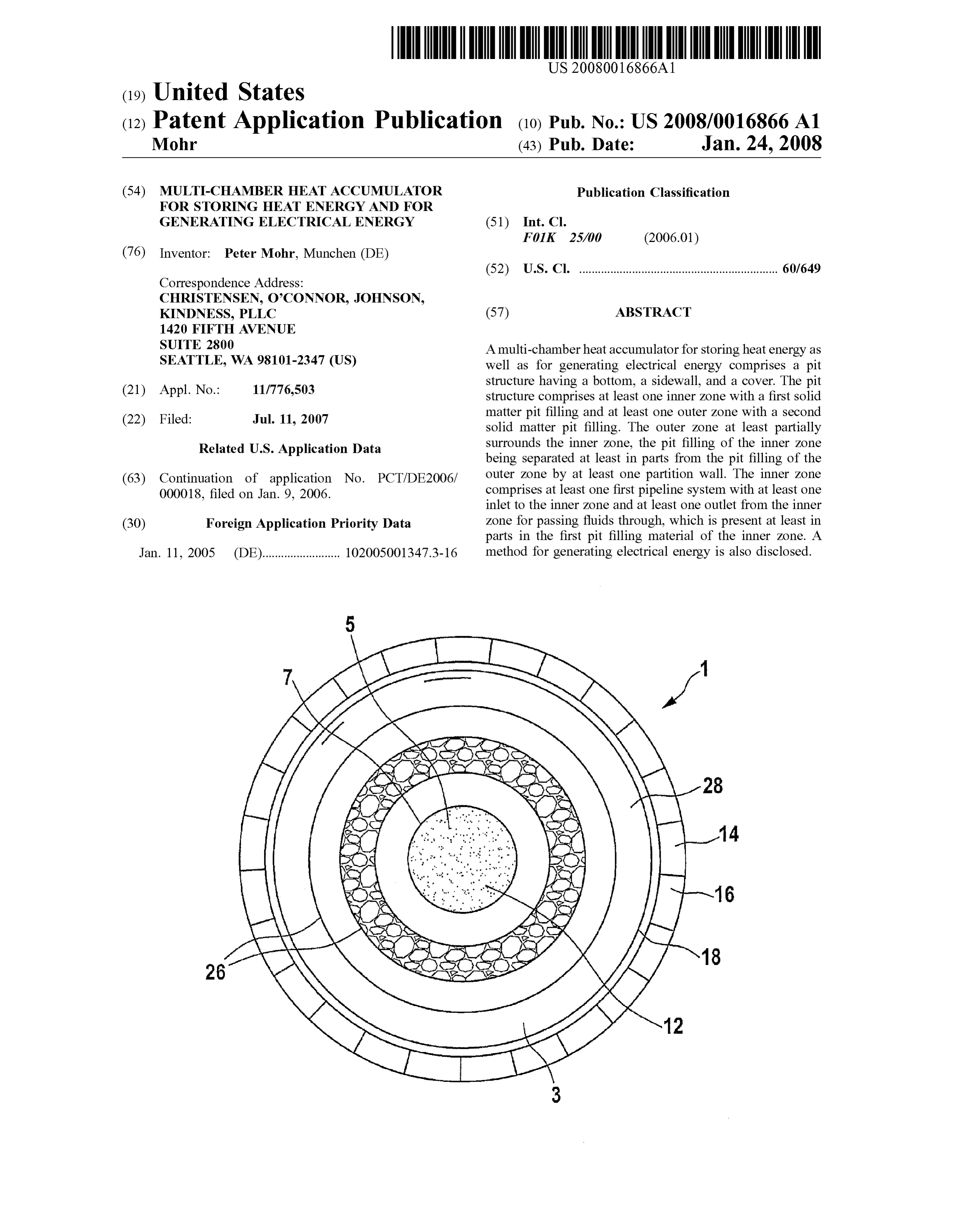
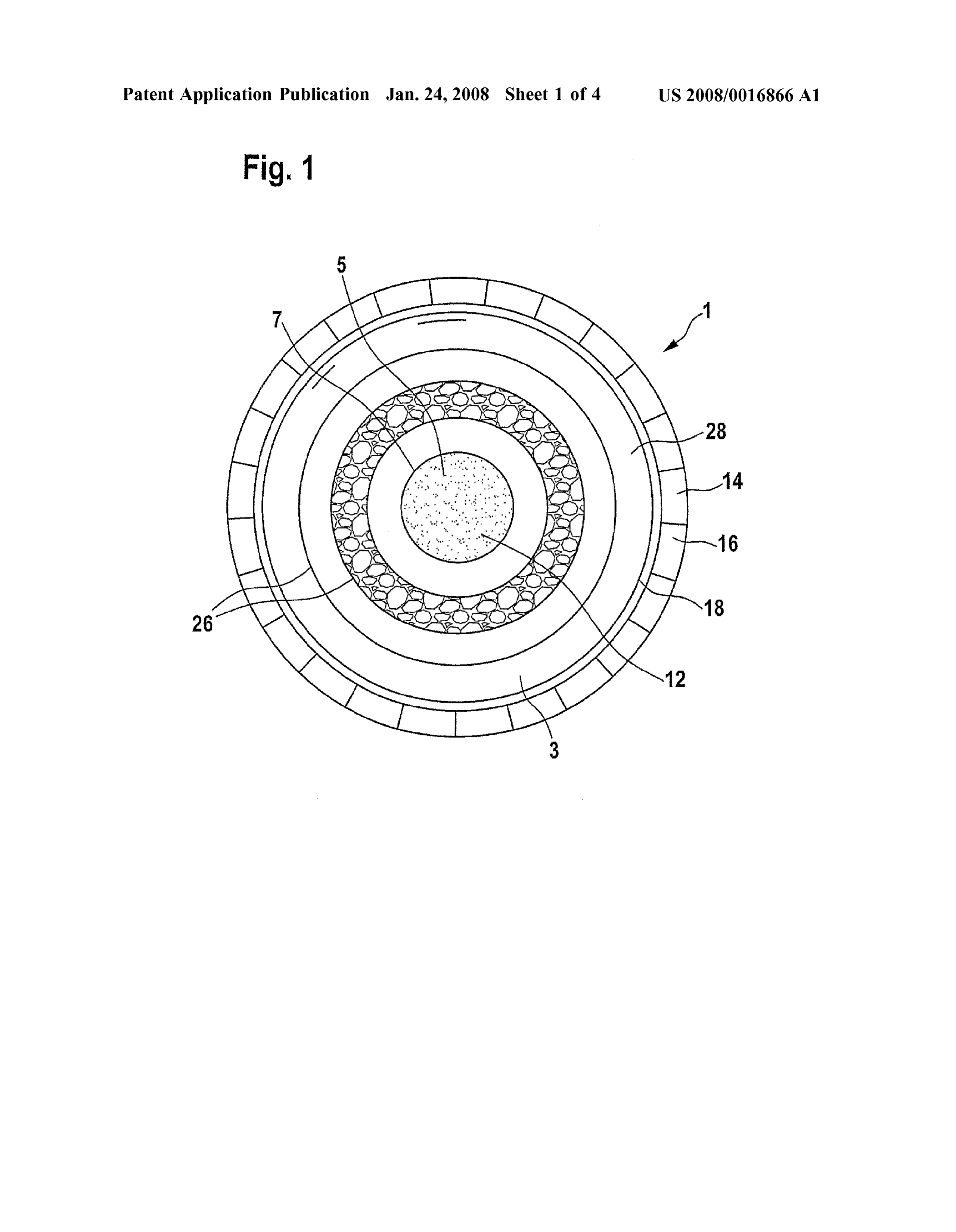
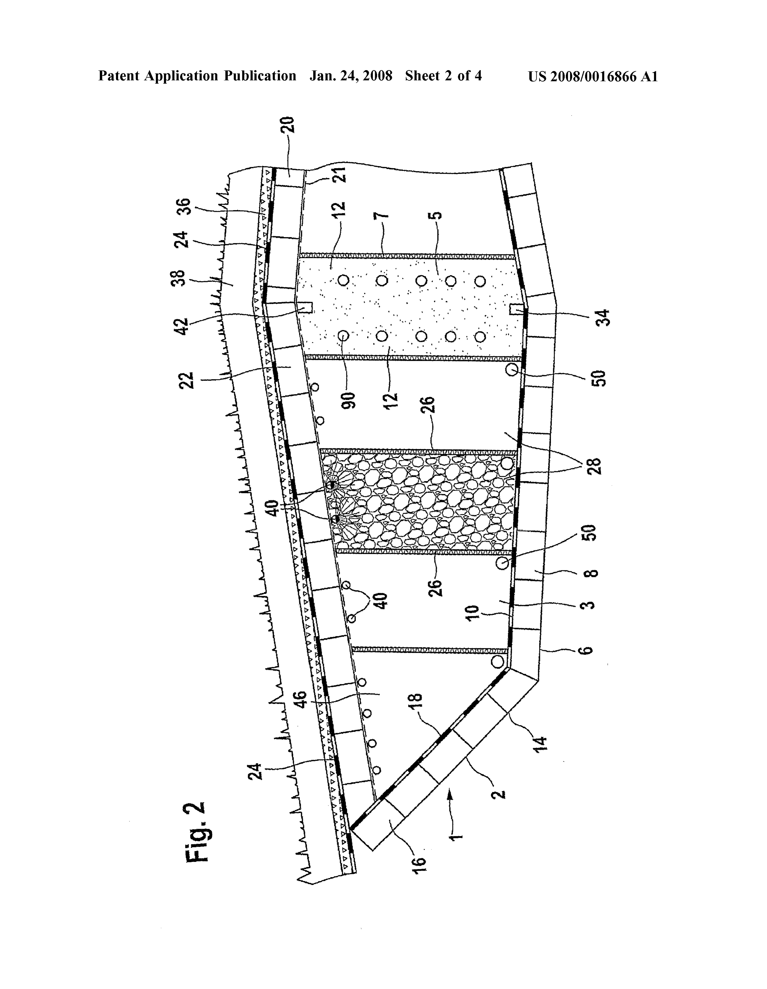
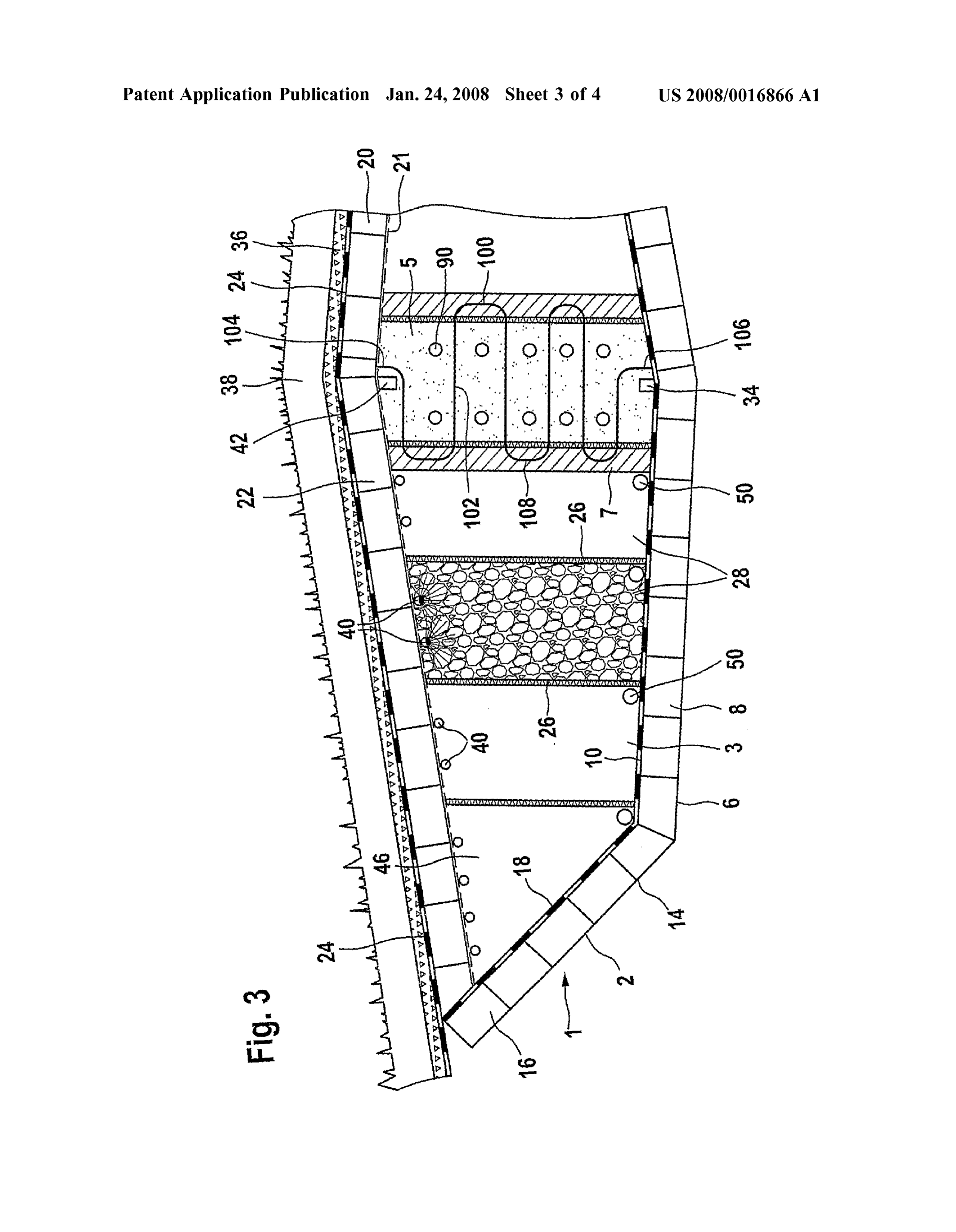
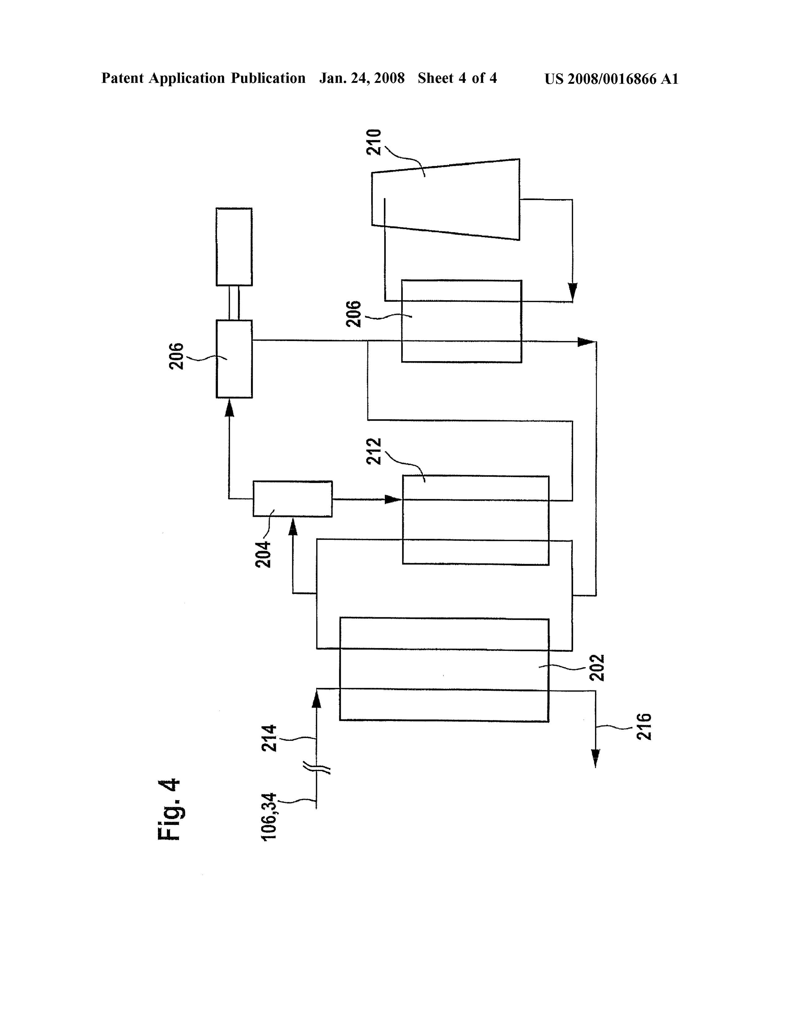
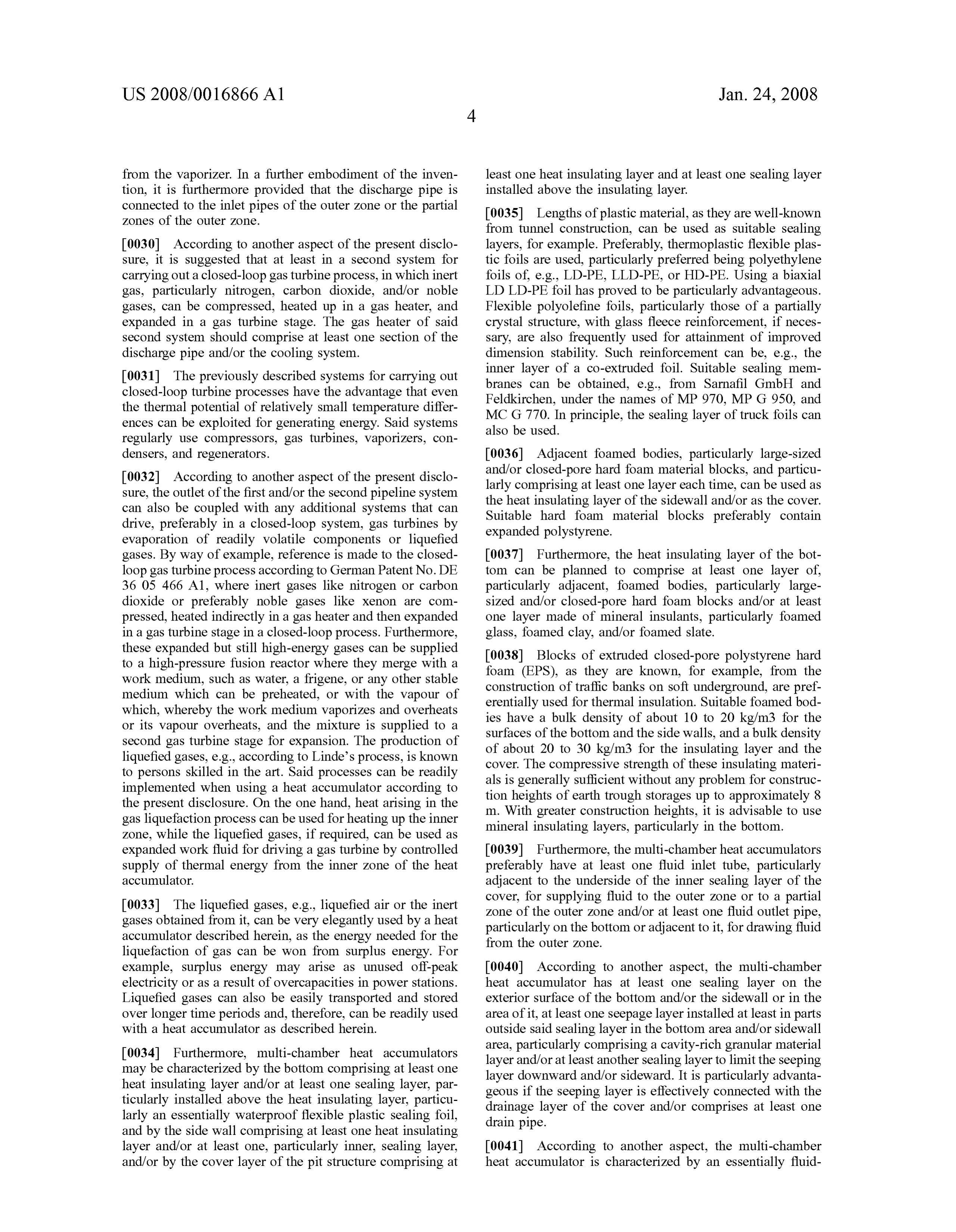
DESCRIPTION OF THE DRAWINGS filling 12. Suitable hard foam blocks are, e.g., made of extruded polystyrene hard foam of a thickness in the range 0067. In the following, an example of an embodiment of of about 0.2 to 1.5 m. In the embodiment shown in FIG. 2, the invention is described in greater detail for better under the sidewall 14 is provided with a heat insulating layer of standing with reference to the accompanied drawings in hard foam material blocks similarly to the bottom and with which: a sealing layer 18 in the form of a plastic layer. The sealing layer 18 is liquid-tightly joined to the sealing layer 10 of the 0068 FIG. 1 is a perspective schematic top view of a bottom as well as to the sealing layer 24 of the cover 20 of multi-chamber heat accumulator; the pit structure 2. The bearing surfaces of the bottom 6 and 0069 FIG. 2 is a schematic cross-sectional detail of the the sidewall 14 are regularly leveled and compacted prior to heat accumulator as shown in FIG. 1; installing the hard foam material blocks. The partition walls 26 of the outer Zone 3 regularly extend from the cover 20 0070 FIG. 3 is a schematic cross-sectional view of an lying on the pit filling to the bottom 6 or the sidewall 14. In alternative embodiment of a multi-chamber heat accumula the present embodiment, the partition walls 26 are made of tor as shown in FIG. 1; and heat insulating plastic boards provided shrink-wrapped in a 0071 FIG. 4 is a schematic representation of a system for plastic wrapping. Such a wall can also be used for the carrying out a Kalina process. partition wall 7 between the inner and the outer Zone. The partition walls 26 as well as the partition wall 7 are prefer
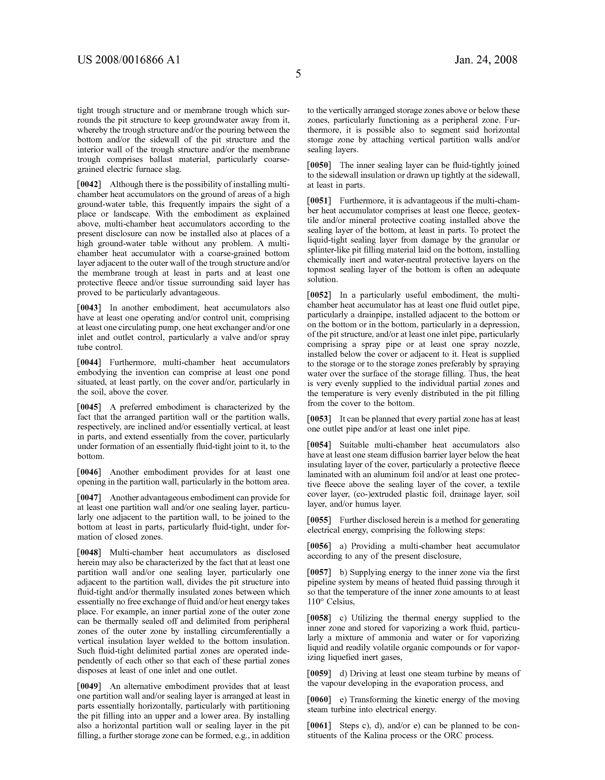
DETAILED DESCRIPTION ably fluid-tightly joined to the floor or the sealing layer lying on the bottom so that no fluid exchange can take place 0072 FIG. 1 is a schematic top view of a multi-chamber between the individual zones. The partial and peripheral heat accumulator 1 according to the invention. The sidewall Zones 28, 46 thus obtained can be operated completely
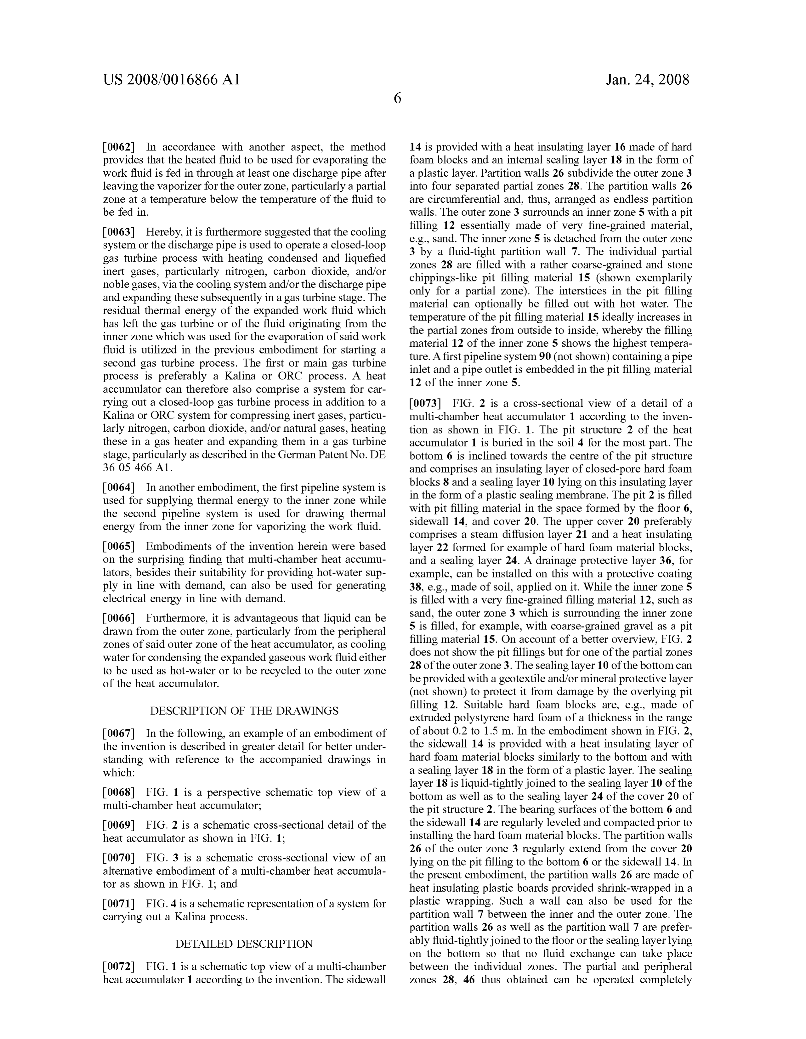
Page 12
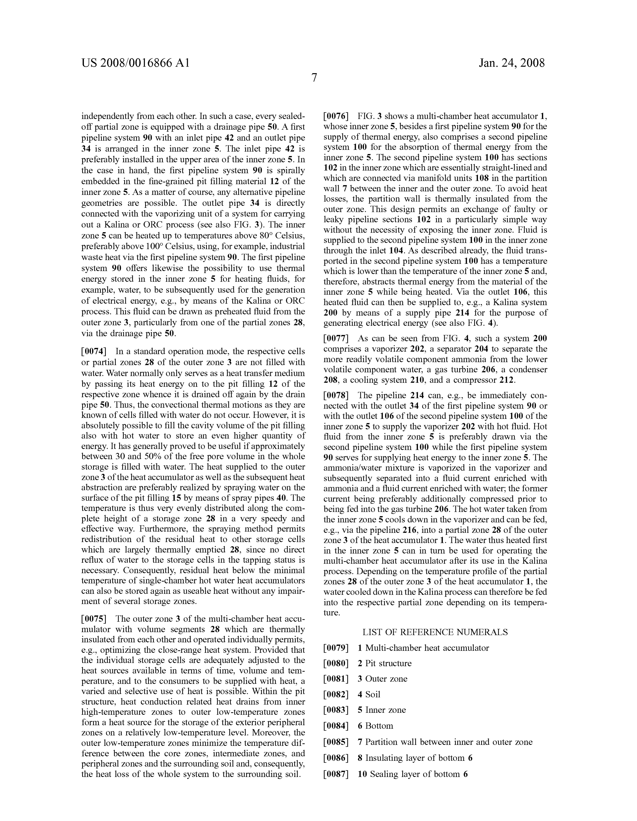
US 2008/00 16866 A1 Jan. 24, 2008
independently from each other. In such a case, every sealed 0076 FIG. 3 shows a multi-chamber heat accumulator 1, off partial Zone is equipped with a drainage pipe 50. A first whose inner Zone 5, besides a first pipeline system 90 for the pipeline system 90 with an inlet pipe 42 and an outlet pipe Supply of thermal energy, also comprises a second pipeline 34 is arranged in the inner Zone 5. The inlet pipe 42 is system 100 for the absorption of thermal energy from the preferably installed in the upper area of the inner Zone 5. In inner Zone 5. The second pipeline system 100 has sections the case in hand, the first pipeline system 90 is spirally 102 in the inner Zone which are essentially straight-lined and embedded in the fine-grained pit filling material 12 of the which are connected via manifold units 108 in the partition wall 7 between the inner and the outer Zone. To avoid heat inner Zone 5. As a matter of course, any alternative pipeline geometries are possible. The outlet pipe 34 is directly losses, the partition wall is thermally insulated from the connected with the vaporizing unit of a system for carrying outer Zone. This design permits an exchange of faulty or out a Kalina or ORC process (see also FIG. 3). The inner leaky pipeline sections 102 in a particularly simple way Zone 5 can be heated up to temperatures above 80° Celsius, without the necessity of exposing the inner Zone. Fluid is preferably above 100° Celsius, using, for example, industrial supplied to the second pipeline system 100 in the inner Zone through the inlet 104. As described already, the fluid trans waste heat via the first pipeline system 90. The first pipeline ported in the second pipeline system 100 has a temperature system 90 offers likewise the possibility to use thermal which is lower than the temperature of the inner Zone 5 and, energy stored in the inner Zone 5 for heating fluids, for therefore, abstracts thermal energy from the material of the example, water, to be subsequently used for the generation inner Zone 5 while being heated. Via the outlet 106, this of electrical energy, e.g., by means of the Kalina or ORC heated fluid can then be Supplied to, e.g., a Kalina system process. This fluid can be drawn as preheated fluid from the 200 by means of a supply pipe 214 for the purpose of outer Zone 3, particularly from one of the partial Zones 28, generating electrical energy (see also FIG. 4). via the drainage pipe 50. 0.077 As can be seen from FIG. 4, such a system 200 0074. In a standard operation mode, the respective cells comprises a vaporizer 202, a separator 204 to separate the or partial Zones 28 of the outer Zone 3 are not filled with more readily Volatile component ammonia from the lower water. Water normally only serves as a heat transfer medium Volatile component water, a gas turbine 206, a condenser by passing its heat energy on to the pit filling 12 of the 208, a cooling system 210, and a compressor 212. respective Zone whence it is drained off again by the drain 0078. The pipeline 214 can, e.g., be immediately con pipe 50. Thus, the convectional thermal motions as they are nected with the outlet 34 of the first pipeline system 90 or known of cells filled with water do not occur. However, it is with the outlet 106 of the second pipeline system 100 of the absolutely possible to fill the cavity volume of the pit filling inner Zone 5 to supply the vaporizer 202 with hot fluid. Hot also with hot water to store an even higher quantity of fluid from the inner Zone 5 is preferably drawn via the energy. It has generally proved to be useful if approximately second pipeline system 100 while the first pipeline system between 30 and 50% of the free pore volume in the whole 90 serves for supplying heat energy to the inner Zone 5. The storage is filled with water. The heat supplied to the outer ammonia/water mixture is vaporized in the vaporizer and Zone 3 of the heat accumulator as well as the Subsequent heat subsequently separated into a fluid current enriched with abstraction are preferably realized by spraying water on the ammonia and a fluid current enriched with water; the former surface of the pit filling 15 by means of spray pipes 40. The current being preferably additionally compressed prior to temperature is thus very evenly distributed along the com being fed into the gas turbine 206. The hot water taken from plete height of a storage Zone 28 in a very speedy and the inner Zone 5 cools down in the vaporizer and can be fed, effective way. Furthermore, the spraying method permits e.g., via the pipeline 216, into a partial Zone 28 of the outer redistribution of the residual heat to other storage cells Zone 3 of the heat accumulator 1. The water thus heated first which are largely thermally emptied 28, since no direct in the inner Zone 5 can in turn be used for operating the reflux of water to the storage cells in the tapping status is multi-chamber heat accumulator after its use in the Kalina necessary. Consequently, residual heat below the minimal process. Depending on the temperature profile of the partial temperature of single-chamber hot water heat accumulators Zones 28 of the outer Zone 3 of the heat accumulator 1, the can also be stored again as useable heat without any impair water cooled down in the Kalina process can therefore be fed ment of several storage Zones. into the respective partial Zone depending on its tempera ture.
0075. The outer Zone 3 of the multi-chamber heat accu mulator with volume segments 28 which are thermally LIST OF REFERENCE NUMERALS insulated from each other and operated individually permits, e.g., optimizing the close-range heat System. Provided that 0079) 1 Multi-chamber heat accumulator the individual storage cells are adequately adjusted to the 0080). 2 Pit structure heat sources available in terms of time, Volume and tem perature, and to the consumers to be supplied with heat, a 0081) 3 Outer Zone varied and selective use of heat is possible. Within the pit 0082) 4 Soil structure, heat conduction related heat drains from inner high-temperature Zones to outer low-temperature Zones 0083) 5. Inner Zone form a heat source for the storage of the exterior peripheral 0084. 6 Bottom
Zones on a relatively low-temperature level. Moreover, the outer low-temperature Zones minimize the temperature dif 0085 7 Partition wall between inner and outer Zone ference between the core Zones, intermediate Zones, and 0086) 8 Insulating layer of bottom 6 peripheral Zones and the Surrounding soil and, consequently, the heat loss of the whole system to the surrounding soil. 0087 10 Sealing layer of bottom 6
Page 13
US 2008/00 16866 A1 Jan. 24, 2008
0088 12 Pit filling of the inner Zone least in parts from the pit filling of the outer Zone by at 0089) 14 Sidewall least one partition wall, and wherein the inner Zone further comprises at least one first pipeline system with 0090 15 Pit filling of the outer Zone at least one inlet to the inner Zone and at least one outlet 0.091 16 Heat insulating layer of the sidewall from the inner Zone for passing fluids through and which is embedded at least in sections in the material 0092] 18 Sealing layer of the sidewall of the first pit filling of the inner Zone. 0093). 20 Cover 2. The multi-chamber heat accumulator according to claim 1, wherein the outer Zone comprises essentially 0094) 21 Steam diffusion layer incompressible granular and/or stone chippings-like mate 0.095 22 Heat insulating layer rial as a second solid matter pit filling. 3. The multi-chamber heat accumulator according to 0096 24 Insulation of the cover claim 1, wherein the material of the first solid matter pit 0097 26 Partition wall filling, on an average, has a lower granulation than the second solid matter pit filling and comprises sand or a 0098) 28 Partial Zone, chamber compact structure at least in parts. 0099 34 Drain pipe, outlet pipe 4. The multi-chamber heat accumulator according to claim 1, wherein the first solid matter pit filling comprises 0100 36 Drainage protective layer incompressible granular and/or stone chippings-like mate rial.
0101 38 Protective layer 5. The multi-chamber heat accumulator according to 0102) 40 Spray pipe claim 1, wherein the partition wall separating the inner and 0103) 42 Inlet pipe the outer Zone from each other is fluid-tight so that essen tially liquid fluids are not interchangeable between the inner 0104 46 Peripheral Zone and the outer Zone.
0105 50 Drainpipe 6. The multi-chamber heat accumulator according to claim 1, wherein the inner Zone contains at least one second 0106 90 First pipeline system pipeline system with at least one inlet to the inner Zone and 01.07 100 Second pipeline system at least one outlet from the inner Zone for passing fluids through, which is embedded at least in parts in the material 0108) 102 Sections of the second pipeline system of the first pit filling of the inner Zone. 0109) 104 Inlet of the second pipeline system 7. The multi-chamber heat accumulator according to claim 1, further characterized by at least one system for 0110 106 Outlet of the second pipeline system carrying out a Kalina process, one first system for carrying 0111) 108 Manifold unit out a closed gas turbine process to expandinert gases, and/or one system for carrying out an ORC process, in each case 0112 200 System for carrying out the Kalina process comprising at least one vaporizer, at least one gas turbine, at 0113 202 Vaporizer least one condenser, at least one compressor and at least one cooling system, in each case coupled with the outlet of the 0114) 204 Separator first and/or the second pipeline system by at least one Supply 0115 206 Gas turbine pipe.
8. The multi-chamber heat accumulator according to 0116 208 Condenser claim 7, further comprising at least one discharge pipe which 0117 210 Cooling system the Supply pipe passes into downstream from the vaporizer. 0118 212 Compressor 9. The multi-chamber heat accumulator according to claim 8, further comprising at least one second system for 0119) 214 Supply pipe carrying out a closed-loop gas turbine process to compress 0120) 216 Discharge pipe inert gases, heat them in a gas heater and expand them in a gas turbine stage, wherein at least one section of the dis 0121 All features represented in the description, the charge pipe and/or of the cooling system represents the gas following patent claims, and the drawings can be imple heater of said second system.
mented to achieve the invention both individually and in any 10. The multi-chamber heat accumulator according to combination with each other. claim 1, wherein the second pit filling of the outer Zone is What is claimed is: subdivided into partial Zones by at least two partition walls 1. A multi-chamber heat accumulator for the storage of and/or at least one circumferential partition wall. heat energy as well as for the generation of electrical energy, 11. The multi-chamber heat accumulator according to comprising: claim 8, wherein the discharge pipe is connected with at least one inlet pipe of the outer Zone or at least one partial Zone a pit structure embedded in the ground, comprising at of the outer Zone.
least one bottom, one sidewall, and a cover, wherein the 12. The multi-chamber heat accumulator according to pit structure comprises at least one inner Zone with a claim 1, wherein the bottom comprises at least one heat first Solid matter pit filling and at least one outer Zone insulating layer and at least one sealing layer installed above which at least partially Surrounds the inner Zone, the insulating layer, and wherein the sidewall comprises at wherein the pit filling of the inner Zone is separated at least one inner sealing layer, and/or that the cover of the pit
Page 14
US 2008/00 16866 A1 Jan. 24, 2008
structure comprises at least one heat insulating layer and at control unit comprising at least one circulating pump, one least one sealing layer installed above the insulating layer. heat exchanger, and one inlet and one outlet, particularly a 13. The multi-chamber heat accumulator according to valve and/or spray pipe control.
claim 12, wherein the heat insulating layer of the sidewall 21. A method for generating electrical energy, comprising: and/or the cover comprises at least one layer of adjacent, providing a multi-chamber heat accumulator according to foamed bodies, particularly large-sized and/or closed-pore claim 1:
hard foam material blocks.
14. The multi-chamber heat accumulator according to Supplying energy to the inner Zone via the first pipeline claim 12, wherein the heat insulating layer of bottom com system by means of heated fluid passing through it so prises at least one layer of adjacent, foamed bodies, particu that the temperature of the inner Zone amounts to at larly large-sized and/or closed-pore hard foam blocks and/or least 110 Celsius;
at least one layer of mineral insulants made of foamed glass, utilizing the thermal energy Supplied to the inner Zone and Swelling clay, and/or Swelling slate. stored for vaporizing a work fluid or for vaporizing 15. The multi-chamber heat accumulator according to liquefied gases;
claim 1, wherein the partition wall for subdividing the outer ones Zone comprises at least one wall of Stone, concrete, driving at least one steam turbine by means of the vapour metal and/or synthetic material, and/or a plastic foil, and that developing in the process of evaporation of the expand the partition wall between the inner and the outer Zone ing work fluid; and comprises at least one wall of Stone, concrete, and/or metal. transforming the kinetic energy of the moving steam 16. The multi-chamber heat accumulator according to turbine into electrical energy. claim 1, further comprising at least one fluid inlet pipe 22. The method according to claim 21, wherein the steps adjacent to the underside of the inner sealing layer of the c), d), and/or e) are constituents of a Kalina process or an cover for Supplying fluid to the outer Zone or to a partial Zone ORC process.
of the outer Zone and/or at least one fluid outlet pipe on the 23. The method according to claim 21, wherein the heated bottom, in said bottom, or adjacent to it, for drawing fluid fluid used for the evaporation of the work fluid is supplied from the outer Zone. through at least one discharge pipe after leaving the vapor 17. The multi-chamber heat accumulator according to izer for the outer Zone, with a temperature below that of the claim 10, wherein each partial Zone of the outer Zone has at fluid to be fed in.
least one outlet pipe and/or at least one inlet pipe. 24. The method according to claim 23, wherein the 18. The multi-chamber heat accumulator according to cooling system or the discharge pipe is used to operate a claim 1, wherein the outer Zone at least in parts is positioned closed-loop gas turbine process in which compressed and lateral, in each case lateral and below, or in each case lateral liquefied inert gases are heated up via the cooling system or and above, in relation to the inner Zone such that the outer the discharge pipe in liquefied and/or vaporized State and Zone Surrounds said inner Zone from all sides. then expanded in a gas turbine stage. 19. The multi-chamber heat accumulator according to 25. The method according to claim 21, wherein the first claim 1, further comprising an essentially liquid-tight trough pipeline system is used for Supplying thermal energy to the structure and/or membrane trough Surrounding the pit struc inner Zone while a second pipeline system is used for ture to keep groundwater away from it, wherein the trough abstracting thermal energy from the inner Zone for vapor structure and/or the pouring between bottom and/or sidewall izing the work fluid.
of the pit structure and the interior wall of the trough 26. A method using the multi-chamber heat accumulator structure and/or the membrane trough comprises ballast in accordance with claim 1 for the provision of thermal material. energy for the generation of electrical energy. 20. The multi-chamber heat accumulator according to claim 1, further comprising at least one operating and/or k k k k k
Provenance
- Collection
- Patents citing this work
- Pages
- 14
- Method
- pdftotext (the PDF's own text layer) + pdftoppm 300dpi page scans
- Patent office record
- patents.google.com →
- Source
- Google Patents citing-documents table
- Assignee
- Peter Mohr
- Inventors
- Peter Mohr
- Published
- 2008-01-24
- Transcribed from
- patentimages.storage.googleapis.com →