patent · US4489563
Generation of energy
25 December 1984
Page 1 — bibliographic record
United States Patent (19) 11 Patent Number: 4,489,563 Kalina (45) Date of Patent: Dec. 25, 1984 54 GENERATION OF ENERGY OTHER PUBLICATIONS 76 Inventor: Alexander I. Kalina, 12214 Clear OTEC Pilot Plant Heat Engine-D. Richards and L. L. Fork, Houston, Tex. 77077 Perini, John Hopkins University, 1979.
21 Appl. No.: 405,942 OTEC-A Comprehensive Energy Analysis-T. C. Carlson et al.
51) Int. Cl........................ F01K 25/06; FO1K 25/10 Primary Examiner-Allen M. Ostrager 52 U.S. C. ...................................................... 60/673 Attorney, Agent, or Firm-Arnold, White & Durkee 58) Field of Search .................................. 60/673, 649 57 ABSTRACT 56) References Cited A method of generating energy which comprises utiliz
427,401 5/1890 Campbell .............................. 60/673 partial distillation of at least portion of a multicompo 3,783,613 1/1974 Billings et al. .......................... 60/38 nent working fluid stream at an intermediate pressure to 4,009,575 3/1977 Hartman, Jr. ... ... 60/648 generate working fluid fractions of differing composi 4,037,415 7/1977 Christopher ... ... 60/673 tions. The fractions are used to produce at least one 4, 10,297 7/1978 Uda ......................................... 55/43 main rich solution which is relatively enriched with 4,183,218 1/1980 Eberly, Jr. ...... ... 60/673 respect to the lower boiling component, and to produce 4,195,485 4/1980 Brinkerhoff ... ... 60/673 X at least one lean solution which is relatively improver 4,297,332 10/1981 Tatani ................................. 423/240 ished with respect to the lower boiling component. The 4,333,313 6/1982 Cardone et al. ... 60/673 X pressure of the main rich solution is increased whereaf 4,346,561 8/1982 Kalina ................................... 60/673 ter it is evaporated to produce a charged gaseous main
FOREIGN PATENT DOCUMENTS working fluid. The main working fluid is expanded to a 248.1362. 10/1981 France .................................. 60/673 low pressure level to release energy. The spent low 481 10 10/1981 Japan ..................................... 60/673 pressure level working fluid is condensed in a main 294882 9/1929 United Kingdom. absorption stage by dissolving with cooling in the lean 352492 7/1931 United Kingdom . solution to regenerate an initial working fluid for reuse.
872874 7/1961 United Kingdom . 37 Claims, 6 Drawing Figures
Page 2
Drawing sheet — no readable text.
Page 3
Drawing sheet — no readable text.
Page 4
Drawing sheet — no readable text.
Page 5
Drawing sheet — no readable text.
Page 6
Drawing sheet — no readable text.
Page 7
(a) subjecting at least a portion of an initial multicom
GENERATION OF ENERGY ponent working fluid stream having an initial con position of lower and higher boiling components,
This invention relates to the generation of energy. to partial distillation at an intermediate pressure in More particularly, this invention relates to a method of 5 a distillation system by means of relatively lower generating energy in the form of useful energy from a temperature heat to generate working fluid frac heat source. The invention further relates to a method tions of differing compositions; of improving the heat utilization efficiency in a thermo (b) using the generated fractions to produce at least dynamic cycle and thus to a new thermodynamic cycle one main rich solution which is relatively enriched utilizing the method. O with respect to a lower temperature boiling com The most commonly employed thermodynamic cycle ponent, and to produce at least one lean solution for producing useful energy from a heat source, is the which is relatively impoverished with respect to a Rankine cycle. In the Rankine cycle a working fluid lower temperature boiling component; such as ammonia or a freon is evaporated in an evapora 15 (c) increasing the pressure of the main rich solution to tor utilizing an available heat source. The evaporated a charged high pressure level and evaporating the gaseous working fluid is then expanded across a turbine main rich solution by means of a relatively higher to release energy. The spent gaseous working fluid is temperature heat to produce a charged gaseous then condensed in a condenser using an available cool main working fluid;
ing medium. The pressure of the condensed working 20 (d) expanding the gaseous main working fluid to a medium is then increased by pumping it to an increased spent low pressure level to release energy; and pressure whereafter the working liquid at high pressure (e) condensing the spent gaseous working fluid in a is again evaporated, and so on to continue with the main absorption stage by dissolving it with cooling cycle. While the Rankine cycle works effectively, it has in the lean solution at a pressure lower than the a relatively low efficiency. The efficiency of the typical 25 intermediate pressure to regenerate the initial Rankine cycle is such that currently the cost of installa working fluid.
tion is in the region of about $1,700 to about $2,200 per lowerantemperature
In embodiment of the invention, the relatively heat may be selected from one or
A thermodynamic cycle with an increased efficiency more members of the group comprising: over that of the Rankine cycle, would reduce the instal 30 (a) a lower temperature portion of the relatively higher temperature heat;
lation costs per Kw. At current fuel prices, such an (b) a portion of the relatively higher temperature heat improved cycle would be commercially viable for uti which is not utilized for evaporating the main rich lizing various waste heat sources. solution;
Applicants prior patent application Ser. No. 143,524 filed Apr. 24, 1980 relates to a system for generating 35 (c)Source; heat from a relatively lower temperature heat energy which utilizes a binary or multicomponent (d) heat recovered from the spent gaseous working working fluid. This system, termed the Exergy system, fluid; and operates generally on the principle that a binary work (e) heat recovered from the main absorption stage. ing fuid is pumped as a liquid to a high working pres The relatively lower temperature heat may conve Sure. It is heated to partially vaporize the working fluid, 40 niently be distributed between the distillation systern it is flashed to separate high and low boiling working and a lower temperature portion of a main evaporation fluids, the low boiling component is expanded through stage to preheat the main rich solution prior to evapora a turbine to drive the turbine, while the high boiling tion thereof in a main evaporation stage. component has heat recovered therefrom for use in heating the binary working fluid prior to evaporation, 45 The method may conveniently include the steps of: (a) increasing the pressure of the initial working fluid and is then mixed with the spent low boiling working stream to a first intermediate pressure; fluid to absorb the spent working fluid in a condenser in (b) dividing the initial working fluid stream into a first the presence of a cooling medium. neutral stream and a first distillation stream; Applicant's Exergy cycle is compared theoretically (c) subjecting the first distillation stream to partial with the Rankine cycle in applicant's prior patent appli 50 distillation in the distillation system to produce a cation to demonstrate the improved efficiency and ad first lower boiling fraction and a first higher boiling vantages of applicant's Exergy cycle. This theoretical fraction;
comparison has demonstrated the improved effective (d) removing the first higher boiling fraction from the ness of applicant's Exergy cycle over the Rankine cycle distillation system to constitute the lean solution: when an available relatively low temperature heat 5 5 and
Source such as surface ocean water, for example, is (e) absorbing the first lower boiling fraction in the employed. first neutral stream to enrich that stream to pro Applicant found, however, that applicant's Exergy duce a first rich solution.
cycle provided less theoretical advantages over the In one preferred embodiment of the invention, the conventional Rankine cycle when higher temperature 60 method may including the step of withdrawing the first available heat sources were employed. rich Solution from the distillation system to constitute It is accordingly an object of this invention to provide the main rich solution.
an energy generating system which would provide an This embodiment of the invention would be en improved efficiency not only when lower temperature ployed in appropriate circumstances where the heating available heat Sources are utilized, but also when higher 65 and cooling mediums which are available and are em temperature waste or available heat sources are utilized. ployed. are such that enrichment of the working fluid In accordance with one aspect of this invention. a can be effected sufficiently in a single distillation stage method of generating energy comprises: to produce a main rich Solution which can be evapo
Page 8
rated effectively with the available relatively higher However, because relatively low temperature heat is temperature heat source. being utilized, the quantity of heat loss will be substan In an alternative embodiment of the invention, where tially less.
justified by the heating and cooling mediums utilized in Relatively lower temperature heat for the distillation practicing the invention, the method may include two, system of this invention may be obtained in the form of three or more distillation stages in the distillation system spent relatively high temperature heat, in the form of with a view to producing a main rich solution which is the lower temperature part of relatively higher temper enriched to a greater extent than in a single stage distil ature heat from a heat source, in the form of relatively lation system. lower temperature waste or other heat which is avail Thus, for example, where the method includes two 10 able from the or a heat source, and/or in the form of distillation steps in the distillation stage, the method relatively lower temperature heat which is generated in may include the step of subjecting the first rich solution the method and cannot be utilized efficiently or more to at least one second distillation step by: efficiently or at all for evaporation of the main rich (a) mixing with the first rich solution a second higher solution.
boiling fraction recycled from a succeeding distilla 15 In practice, any available heat, particularly lower tion stage of the distillation system to produce a temperature heat which cannot be used or cannot be second working fluid stream; used effectively for evaporating the main rich solution, (b) increasing the pressure of the second working may be utilized as the relatively lower temperature heat fluid stream to a second higher intermediate pres for the distillation system. In the same way such rela sure; tively lower temperature heat may be used for preheat (c) dividing the second working fluid stream into a ing the main rich solution in a preheater or in a lower second neutral stream and a second distillation temperature part of the main absorption stage. stream; In one embodiment of the invention, at least part of (d) subjecting the second distillation stream to partial the lean solution may be used as a second working fluid distillation in the distillation system to produce a 25 by having its pressure increased, by being evaporated in second lower boiling fraction, and to produce the a second main evaporator stage, by being expanded to second higher boiling fraction which is recycled release energy, and by then being condensed with the and mixed with the first rich solution; and other spent main working fluid and with any remaining (e) absorbing the second lower boiling fraction in the part of the lean solution in an absorption stage. second neutral stream to produce a second rich 30 In this embodiment of the invention, the second solution which has a greater enrichment than the working fluid and the main working fluid may be ex first rich solution. panded independently, for example, through separate It will be appreciated that the distillation system can turbines or the like, to release energy. be adjusted and altered in various ways to accommo This embodiment of the invention may be utilized date the heat sources which are available and to provide 35 where the higher temperature heat source which is the most effective production of rich and lean solution available for use in carrying out the process of this streams for use in the method of this invention. invention, is such that the pressure of the main rich While the main rich solution may be evaporated par solution could be increased above the capacity of the tially in the evaporation stage, it is preferred that the main evaporator and the turbine or other expansion/en main rich solution be evaporated substantially or prefer 40 ergy release means, and yet still be capable of effective ably completely in the main evaporation stage. In this evaporation in the main evaporator. In this event the way all heat utilized in evaporating the main rich solu second working fluid which is relatively impoverished tion will be effective in providing the charged high with regard to the low boiling components, could be pressure working fluid which is available to be ex heated first by the high temperature heat source so that panded and thereby release or generate energy. 45 it will be evaporated effectively at a lower pressure If the main rich solution is evaporated only partially. which is compatible with the pressure capacities of the some of the main rich solution which is not evaporated, main evaporator and the turbine. The spent very high will have been heated to a relatively high temperature, temperature heat from such evaporation can then be but will not be available to generate energy. This will used in Series for evaporating the main rich solution at a therefore reduce the efficiency of the process. 50 convenient pressure. Thereafter, the remaining spent Even if the portion of the main rich solution which is lower temperature heat can be utilized in the distillation not evaporated is utilized for heat exchange purposes to system of the invention.
supply heat to the main rich solution prior to evapora In a similar embodiment of the invention, the initial tion and/or to supply heat for utilization in the distilla working fluid stream may be treated in the distiliation tion stage, substantial energy losses will occur in the system to produce in addition to the lean solution. a heat exchange system because of the relatively high plurality of rich solution streams having differing com temperature heat which is involved. positions. In this embodiment, the rich solution streams By evaporating the main rich solution substantially may be separately treated to increase their pressures, to completely in a main evaporation state using a relatively evaporate them and to expand them, with the evapora high temperature heat, and utilizing all or substantially 60 tion of each rich solution stream being effected with a all of the evaporated main rich solution as the charged heat Source temperature range appropriate for the spe gaseous working fluid for releasing energy, applicant cific composition range of the rich solution stream. believes high temperature energy utilization will be the In one preferred application of the method of this most efficient. invention, the enrichment of portion of the working By using relatively low temperature heat for partial 65 fluid stream may, in each distillation stage of the distilla distillation in the distillation system heat losses will be tion system, be increased to the maximum extent possi Substantially less. Heat losses will naturally still occur in ble consistent with effective distillation of the distilia the heat exchanger systems of the distillation system. tion stream in that stage with the available lower tem
Page 9
perature heat source, and consistent with effective con (a) feeding an initial multicomponent working fluid densation of the lower boiling fraction in the neutral stream to a partial distillation system; stream with an available cooling medium in each distil (b) increasing the pressure of the stream to an inter lation stage to produce a main rich solution which may mediate pressure;
be pumped to high pressure prior to effective evapora (c) separating the stream into a neutral stream and a tion. distillation stream;
Various types of heat sources may be used to drive (d) subjecting the first distillation stream to partial the cycle of this invention. Thus, for example, applicant distillation to produce working fluid fractions of anticipates that heat sources may be used from Sources differing compositions;
as high as say 1,000 F. or more, down to heat sources O (e) withdrawing the fraction comprising a lean liquid such as those obtained from ocean thermal gradients. solution which is impoverished with respect to a Heat sources such as, for example, low grade primary lower boiling component, from the distillation fuel, waste heat, geothermal heat, solar heat and Ocean Stage;
thermal energy conversion systems are believed to all (f) mixing the fraction comprising an enriched vapor be capable of development for use in applicant's inven 15 which is enriched with respect to a lower boiling tion. component, with the neutral stream and condens The working fluid for use in this invention may be ing it therein by means of a cooling medium to any multicomponent working fluid which comprises a form an enriched liquid stream; mixture of two or more low and high boiling fluids. The (g) increasing the pressure of the enriched liquid fluids may be mixtures of any of a number of com 20 stream;
pounds with favorable thermodynamic characteristics (h) substantially evaporating the enriched liquid and having a wide range of solubility. Thus, for exam stream in an evaporation stage to produce a ple, the working fluid may comprise a binary fluid such charged working fluid vapor; as an ammonia-water mixture, two or more hydrocar (i) expanding the charged working fluid vapor to bons, two or more freons, or mixtures of hydrocarbons 25 release energy and produce a spent working fluid and freons.
Enthalpy-concentration diagrams for ammonia-water vapor; and are readily available and are generally accepted. An (j) mixing the spent vapor with the lean liquid solu monia-water provides a wide range of boiling tempera tion and condensing it therein in an absorption tures and favorable thermodynamic characteristics. 30 stage to regenerate the initial working fluid stream. Ammonia-water is therefore a practical and potentially In general, standard equipment may be utilized in useful working fluid in most applications of this inven carrying ment out the method of this invention. Thus, equip such as heat exchangers, tanks, pumps, turbines, tion. Applicant believes, however, that when equip valves and fittings of the type used in a typical Rankine ment economics and turbine design become paramount cycles, may be employed considerations in developing commercial embodiments this invention. Applicant inbelieves
that the constraints of the invention, mixtures of freon-22 with toluene and other hydrocarbon or freon combinations will become upon materials of construction would be the same for more important for consideration. this invention as for conventional Rankine cycle power The invention further extends to a method of improv or refrigeration systems. Applicant believes, however, ing the heat utilization efficiency in a thermodynamic 40 that higher thermodynamic efficiency of this invention cycle using a multicomponent working fluid having will result in lower capital costs per unit of useful en components of lower and higher boiling point, which ergy recovered, primarily saving in the cost of heat method comprises: exchange and boiler equipment. In applications such as (a) utilizing relatively lower temperature heat to ef geothermal and solar sources, where heat conversion fect partial distillation of at least portion of the 45 equipment would tend to be a small part of the total working fluid for producing working fluid frac investment required to produce or collect heat. the high tions which have differing compositions; and efficiency of the invention would produce a greater (b) utilizing relatively higher temperature heat to energy output. Therefore, it would reduce the total cost completely evaporate at least an enriched portion per unit of energy produced.
of the working fluid which has been enriched with 50 The expansion of the working fluid from a charged respect to a lower boiling component, to produce a high pressure level to a spent low pressure level to gaseous working fluid. release energy may be effected by any suitable conven The invention furhter extends to a method of generat tional means known to those skilled in the art. The ing useful energy from an available heat source, which energy so released may be stored or utilized in accor comprises: 5 5 dance with any of a number of conventional methods (a) subjecting a multicomponent working fluid hav known to those skilled in the art.
ing components of differing boiling points, to par In a preferred embodiment of the invention, the tial distillation in a distillation stage to produce an working fluid may be expanded to drive a turbine of enriched working fluid liquid stream which is en conventional type.
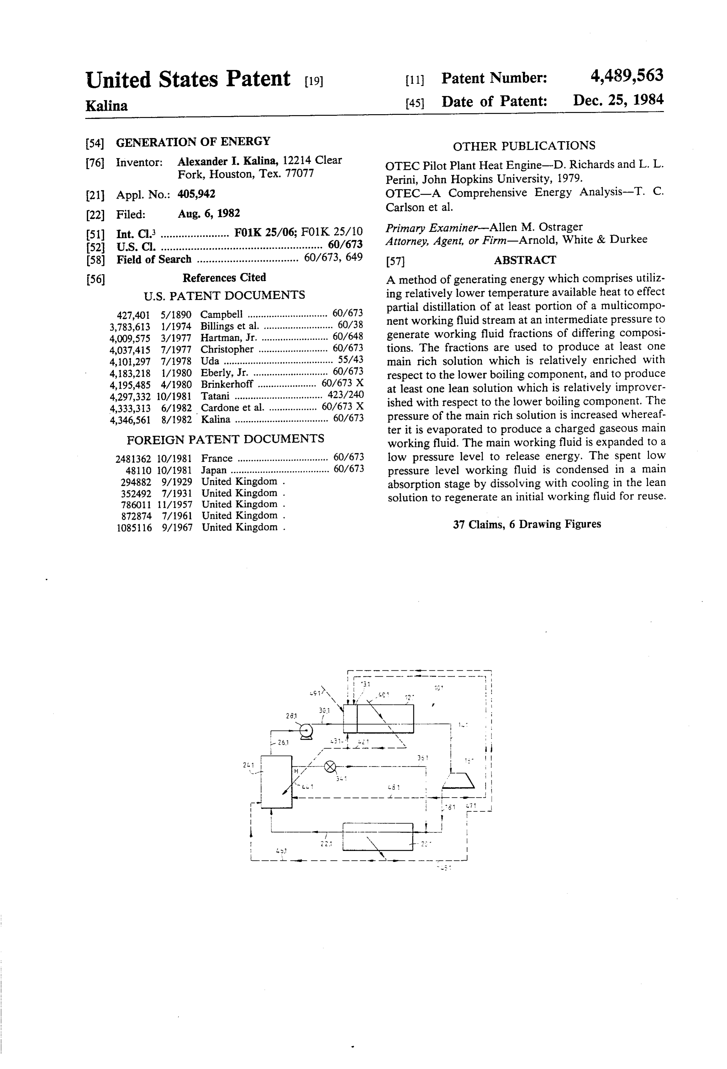
riched with respect to a lower boiling point com 60 Preferred embodiments of the invention are now ponent; described by way of example with the reference to the (b) evaporating the stream substantially completely accompanying drawings.
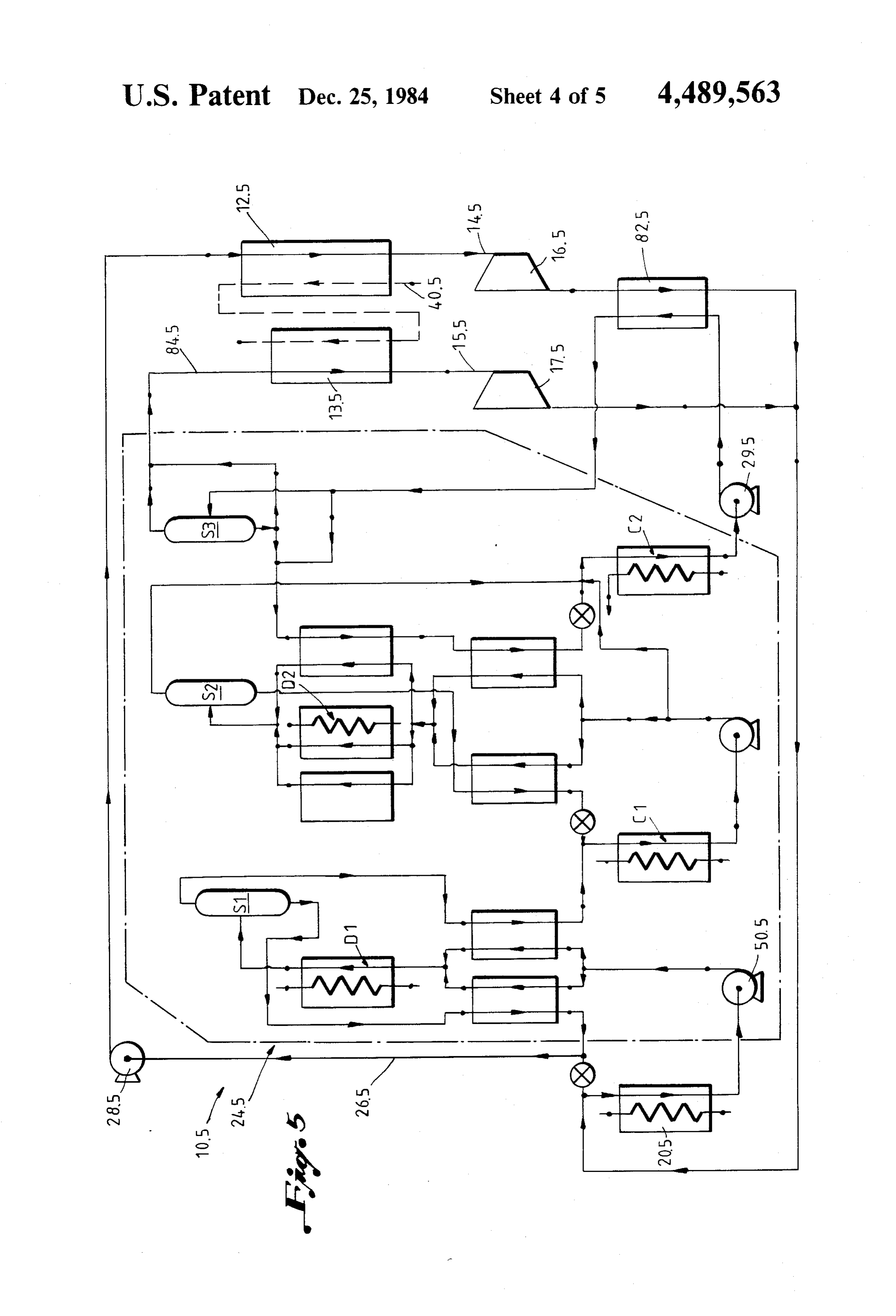
to produce a vaporized charged working fluid; and In the drawings:
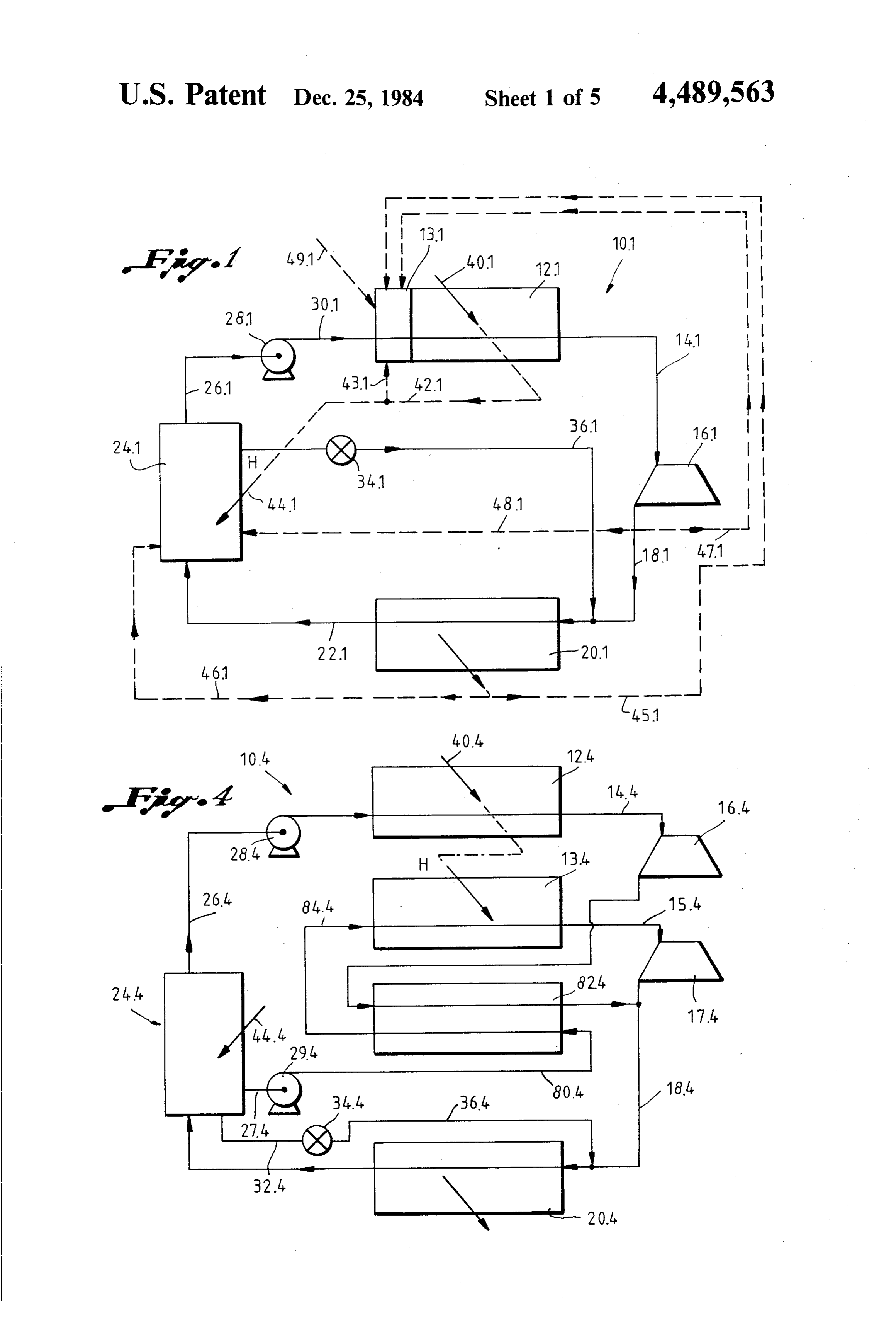
(c) expanding the charged working fluid to release FIG. 1 shows a simplified schematic representation of energy. one system for carry out the method of this invention: Still further in accordance with the invention there is FIG. 2 shows a more detailed schematic representa provided a method of generating energy, which com tion of one embodiment in accordance with the System prises: of FIG. :
Page 10
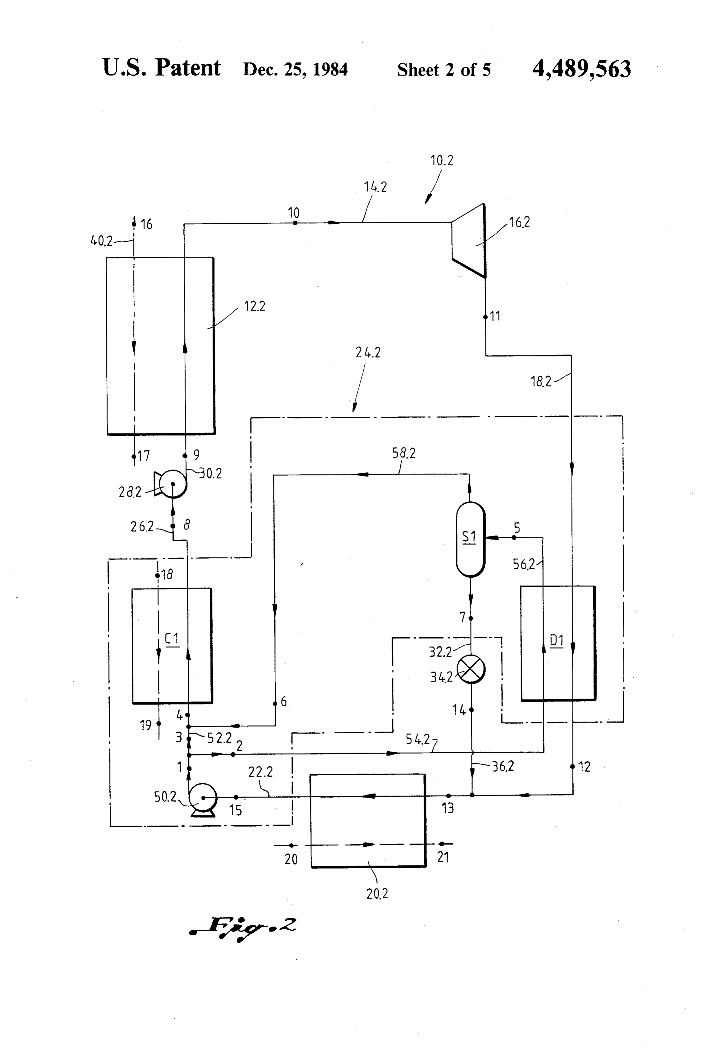
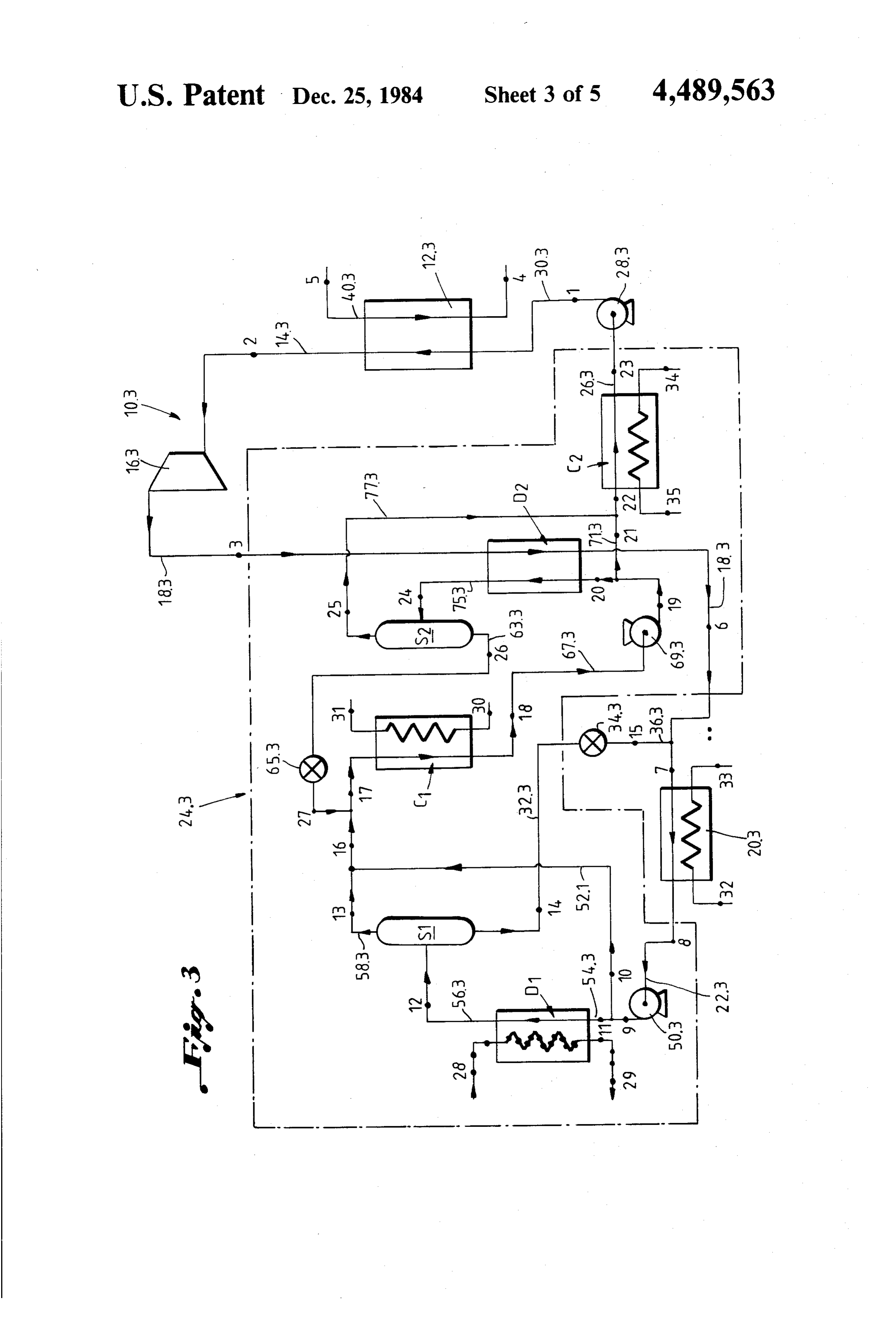
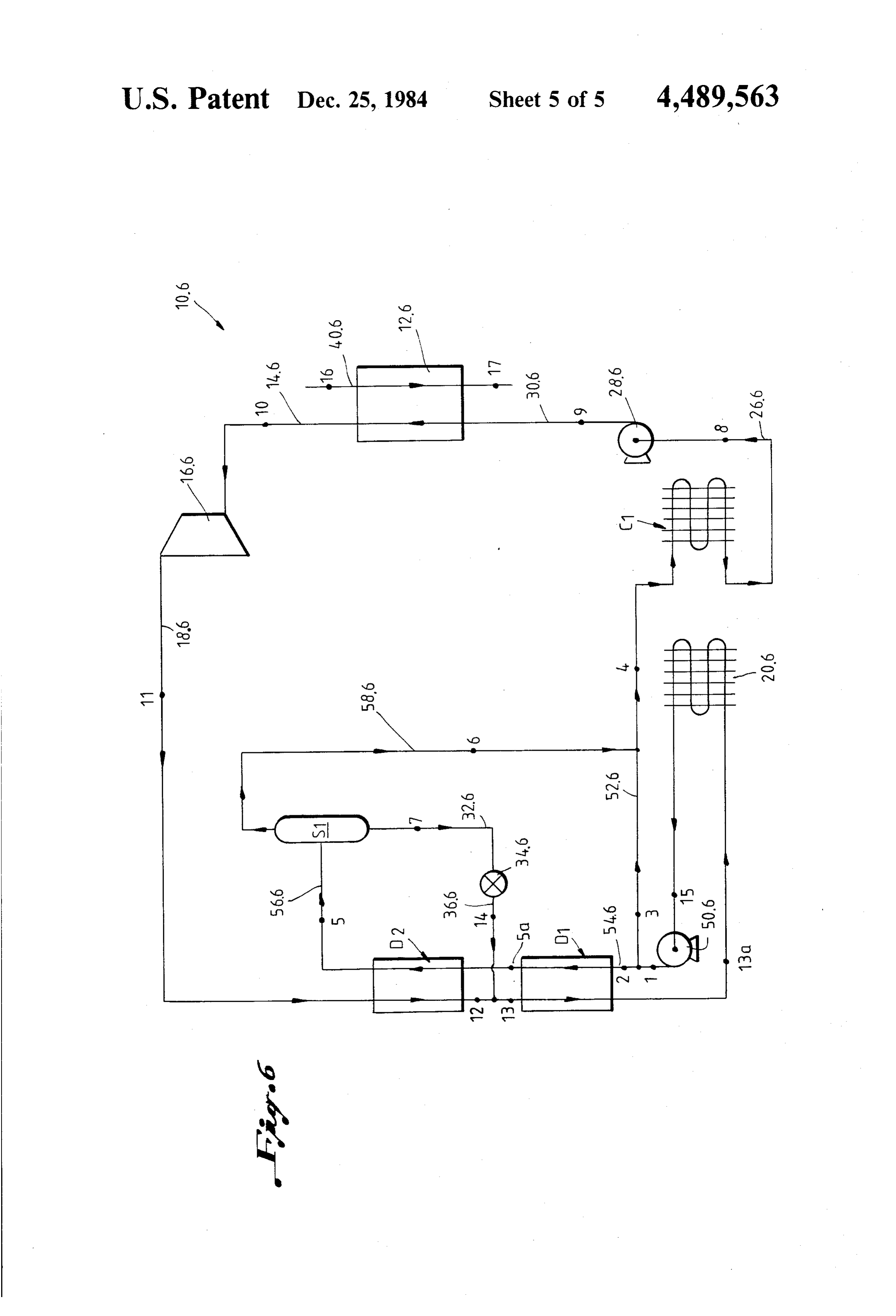
FIG. 3 shows a more detailed schematic representa ence numeral 40.1. The relatively higher temperature tion of an alternative embodiment in accordance with heat 40.1 is fed to the main evaporation stage 12.1 for the system of FIG. 1; evaporating the main rich solution completely. FIG. 4 shows a simplified schematic representation of The spent relatively higher temperature heat from an alternative system for carrying out the method of this 5 the main evaporation stage 12.1 which, because of the invention; conventional pinch point, cannot be utilized efficiently FIG. 5 shows a more complete schematic representa in the main evaporation stage 12.1, now becomes rela tion of one embodiment in accordance with the system tively lower temperature heat. This spent heat may of FIG. 4; therefore be fed along dotted line 42.1 to constitute FIG. 6 shows a schematic representation of yet a 10 relatively lower temperature heat 44.1 which is fed to further alternative system in accordance with this in the distillation system 24.1 for effecting partial distilla vention for utilizing heat in the form of geothermal tion of the portion of the working fluid in the distillation heat. system.
With reference to FIG. 1 of the drawings, reference In addition to the spent relatively higher temperature numeral 10.1 refers generally to one embodiment of a 15 heat which is fed to the distillation system as the rela thermodynamic system or cycle in accordance with this tively lower temperature heat 44.1, relatively lower invention. temperature heat may also be obtained from another The system or cycle 10.1 comprises a main evapora relatively lower temperature available heat source and tion stage 12.1, a turbine 16.1, a main absorption stage Mor from the heat extracted from the main absorption 20.1, a distillation system 24.1, and a main rich solution 20 stage 20.1 as indicated by dotted line 46.1 and/or from pump 28.1. heat recovered from the spent gaseous working fluid In use, using an ammonia-water working solution as between the turbine 16.1 and the main absorption stage the binary working fluid, an initial working fluid stream 20.1 as indicated by dotted line 48.1. at an initial low pressure will flow from the main ab The available heat can be used in a large number of sorption stage 20.1 to the distillation system 24.1 along 25 combinations to provide for effective utilization line 22.1. In the distillation system 24.1, the initial work thereof. The way in which the heat will be utilized both ing fluid stream would have its pressure increased to an for evaporation of the working fluid and for partial intermediate pressure and would be split into a neutral distillation in the distillation system 24.1, will therefore stream and a distillation stream (not shown in FIG. 1). vary depending upon the apparatus employed, the ca The distillation stream would be subjected to partial 30 pacity of the turbine 16.1, the working fluid employed, distillation using a low temperature heat source to gen the type of heat utilized as the heat source, and the erate working fluid fractions of differing composition. availability of relatively low temperature heat and rela The fraction which is enriched with respect to the low tively high temperature heat.
boiling component, namely enriched with respect to Thus, for example, in the embodiment of FIG. 1, the ammonia, would then be added to the first neutral 35 main evaporation stage 12.1 may include a preheater stream and would be condensed in a condenser within stage or a low temperature stage 13.1. Relatively lower the distillation system 24.1 to produce a main rich solu temperature heat may be fed to the stage 13.1 to preheat tion stream leaving the distillation system along line the main rich solution prior to evaporation. 26.1 and flowing to the main rich solution pump 28.1. Such relatively lower temperature heat may be: The main rich solution would then be pumped by 40 (a) at least portion of the relatively low temperature means of the pump 28.1 to a higher pressure, and then heat 44.1 which is diverted from dotted line 42. flows along the line 30.1 to the main evaporation stage and fed to the stage 13.1 along line 43.1; 12.1 where it is evaporated completely with a relatively (b) at least portion of the heat extracted from the higher temperature heat source to form a charged high higher temperature portion of the main absorption pressure gaseous working fluid. 45 stage 20.1 and fed to the stage 13.1 along line 45.1; The charged gaseous working fluid is then conveyed (c) at least portion of the heat recovered from the along line 14.1 to the turbine 16.1 where it is expanded spent gaseous working fluid downstream of the to release energy. The spent gaseous working fluid is turbine 16.1 and fed to the stage 13.1 along line then discharged from the turbine 16.1 along the line 18.1 47.1; and/or to the main absorption stage 20.1. The working fluid is 50 (d) relatively lower temperature heat from an avail conveniently expanded to the initial low pressure level. able heat source and fed to the stage 13.1 along line The fraction of working fluid which is produced in 49.
the distillation system 24.1 which is impoverished with With reference to FIG. 2 of the drawings, reference respect to the lower boiling component, namely the number 10.2 refers to a more detailed schematic repre annonia, constitutes a high temperature boiling or lean 55 sentation of a first embodiment of the system of FIG. 1. solution stream which leaves the distillation system 24.1 The system or cycle 10.2 corresponds essentially with along line 32.1. The lean solution has its pressure re the system 10.1. Corresponding parts are therefore indi duced across a pressure reducing valve 34.1, and the cated by corresponding reference numerals except that reduced pressure lean solution flows along line 36.1 to the suffix "0.1" has been replaced by the suffice "0.2.' the main absorption stage 20.1. 60 In the system 10.2, the distillation system 24.2 has In the main absorption stage 20.1 the spent gaseous been enclosed in a chain dotted line to identify the por working fluid is condensed by being absorbed into the tions of the system forming the distillation system 24.2. lean Solution while heat is extracted therefrom in the The initial working fluid stream at an initial low pres main absorption stage 20.1 by utilizing a suitable avail sure flows along the line 22.2 from the main absorption able cooling medium. 65 stage 20.2 into the distillation system 24.2. The initial The relatively higher temperature heat from the working fluid stream flows to an intial pump 50.2 where waste or other heat source utilized in carrying out the the pressure of the stream is increased to an intermedi System or cycle of this invention is indicated by refer ate pressure.
Page 11
On the downstream side of the initial pump 50.2, the illustrated in FIG. 2 of the drawings, only the heat initial working fluid stream is separated into a first neu available from the exhaust gas was utilized as a heat tral stream which flows along line 52.2, and a first distil source since the lower temperature heat was not re lation stream which flows along line 54.2. quired. - The distillation system 24.2 includes a first distillation In the embodiment illustrated in FIG. 3, however, stage D1 which is in the form of a heat exchanger to heat available in the form of exhaust gas as well as heat place the first distillation stream flowing along the line available in the form of jacket water was utilized as the 54.2 in heat exchange relationship with spent gaseous heat source.
working fluid flowing along the line 18.2. The De Laval engine was a model DSRV-12-4 of Relatively lower temperature heat from the spent 10 Transamerica De Laval, Inc. "Enterprise'. It had a gaseous working fluid causes partial distillation of the gross bhp rating of 7,390 and a net bhp rating of 7,313. first distillation stream in the first distillation stage D1 to The available heat sources which could be utilized generate working fluid fractions of differing composi from the waste heat of the De Laval diesel engine are as tions which flow along the line 56.2 to a first separator follows:
The first separator stage S1 may be provided by a
EXHAUST GAS
separator stage of any conventional suitable type known to those skilled in the art. T 750 F. 3.19.9° C. In the separator stage S1 the working fluid fractions H (heat in T2 200 93.3° C.
become separated into a lower boiling fraction and a 20 exhaust gas higher boiling fraction. The higher boiling fraction above 200 F.)
which is impoverished with respect to the ammonia, flows out of the distillation system 24.2 along line 32.2 through the pressure release valve 34.2 and then through the line 36.2 to the main absorption stage 20.2. 25 JACKET WATER
The lower boiling fraction which is enriched with T1 75° F. 79.44 C.
respect to the ammonia flows along line 58.2 and is T2 163 F. 72.78° C. mixed with the first neutral stream flowing along line H 8.440,300 BTU/hr. 2,027,130 Kcal/hr. 52.2 to enrich the first neutral stream. The lower boiling fraction is therefore absorbed in the first neutral stream 30 in a first condensation stage C1 to form a first rich solu tion stream which leaves the first condensation stage LUBRICATING OIL C1. T 75° F. 79.44 C. In the system 10.2, the distillation system 24.2 com T2 153 F. 67.22 C. prises only a single distillation unit. The first rich solu 35 H 2.43,290 BTU/hr. 608, 39 Kcal/hr. tion stream which leaves the first condensation stage C1 therefore constitutes the main rich solution stream which leaves this distillation system 24.2 along the line EXERGY IN AVAILABLE HEAT SOURCE 26.2 and flows to the main rich solution pump 28.2 Exergy is defined at the initial cooling water tempera where its pressure is increased prior to evaporation in 40 ture of 85 F. and final temperature of 105 F. Exergy in the main evaporation stage 12.2. heat sources having an initial temperature less than 160 In the cycle 10.2, cooling water at ambient tempera F. is considered de minimus and has been ignored. The ture is employed both in the main absorption stage 20.2 exergy in available heat sources is:
and in the first condensation stage C1 to effect absorp (a) exhaust gas-1,431.4 Kw or 1,230,607 Kw/hr, tion of gaseous fractions into liquid fractions in these 5 (b) jacket water-277.9 Kw or 238, 190 Kcal/hr, two stages. For the relatively higher temperature heat (c) lubrication oil-78.3 Kw or 67,329 Kcal/hr, to effect evaporation of the main rich solution in the (d) total-1,787.5 Kw or 1,536.846 Kcal/hr. main evaporation stage 12.2, exhaust gases from a De In the case study which was performed, the tempera Laval diesel engine is utilized to flow along the line tures, pressures and concentrations were ascertained 4.0.2. 50 from water-ammonia enthalpy/concentration diagrams A case study was prepared to illustrate the recovery which are available in the literature.
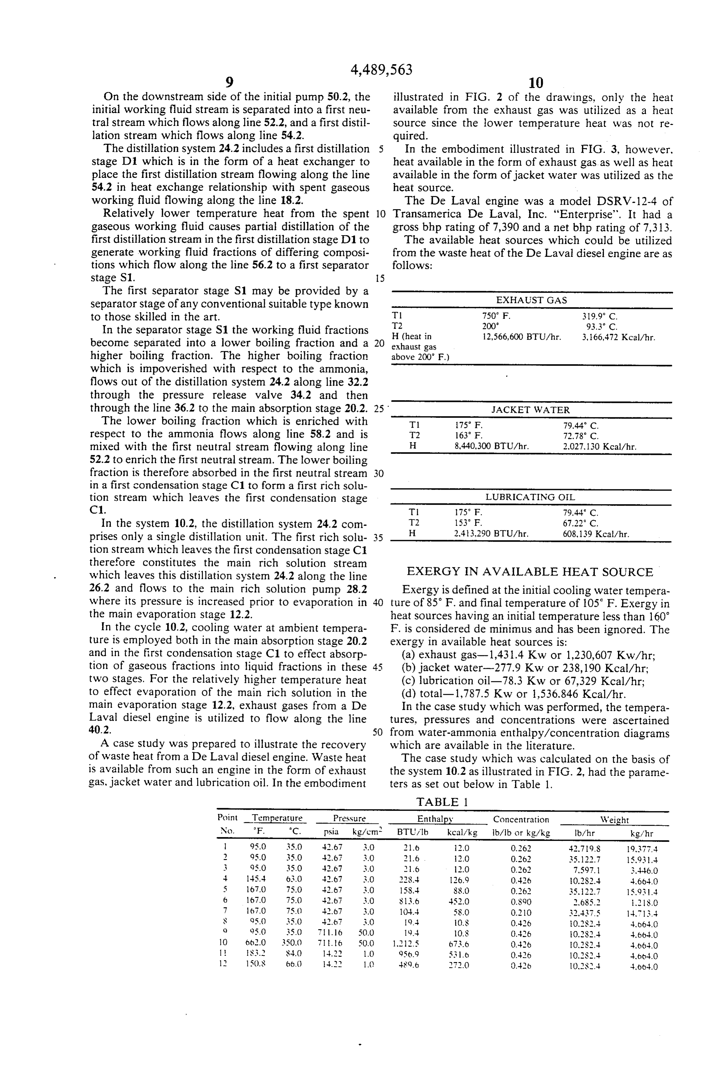
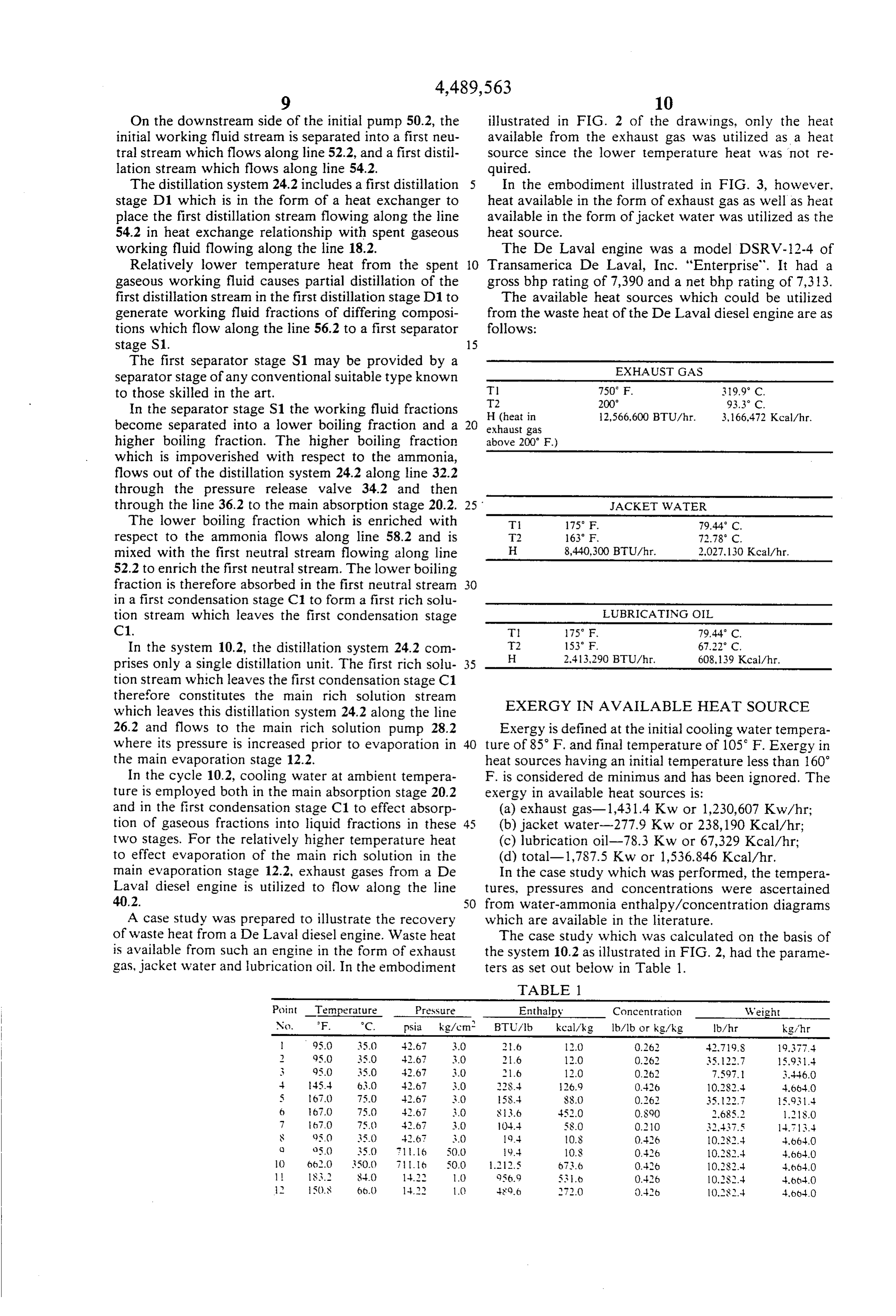
of waste heat from a De Laval diesel engine. Waste heat The case study which was calculated on the basis of is available from such an engine in the form of exhaust the system 10.2 as illustrated in FIG. 2, had the parame gas, jacket water and lubrication oil. In the embodiment ters as set out below in Table 1.
TABLE 1
Point Temperature Pressure - Enthalpy Concentration Weight N. F. C. psia kg/cm, BTU/lb kcal/kg lb/lb or kg/kg b/hr. kg/hr l 95.0 35.0 42.67 3.0 21.6 12.0 0.262 42.79.S 9,377.4
3. Q5.0 350 42.67 3.0 2,6 12.0 0.262 7,597.1 3.446.0
5 167.0 750 42.67 S.O 15S.- SS.0 0.262 35, 22.7 15.931: 6 1670 750 42.67 3.0 813.6 452.0 O.S.90 ,685. 18.0 7 67.0 75.) 42.67 3.0 104.4 58.0 0.210 32437.5 14.13. S Q5.0 35.0 42.67 3.0 19.4 0.8 0.426 0.2S2.-- 4,664.0 Q o50 35.0 16 500 19.4 0.8 0.426 0.282.4 4.66.4.0 10 6.2.0 350.O 76 SO.O 1212.5 b736 0.426 0,2S2.4 4,664.0 S3. S-40 1-4.2.2 1.0 956.9 536 0.426 10.2S2.4 4.66-4.0 l 15().8 6.0 4. 1. 489.6 7.0 0.42b O.S.-4 4.664.0
Page 12
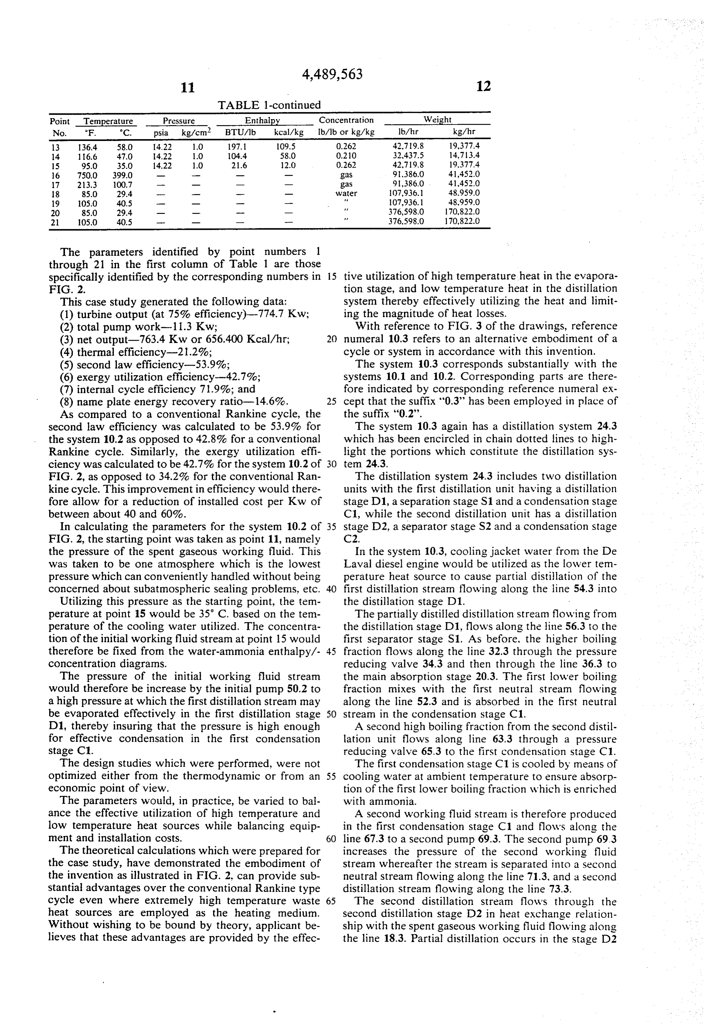
TABLE 1-continued
Point Temperature Pressure Enthalpy Concentration Weight No. F. °C. psia kg/cm2 BTU/lb kcal/kg b/lb or kg/kg b/hr kg/hr 13 36.4 58.0 4.22 1.O 1971 09.5 0.262 42.79.8 19,377.4 14 116.6 47.0 4.22 1.O 104.4 58.0 0.210 32437.5 14,713.4 5 95.0 35.0 14.22 O 21.6 12.0 0.262 42.79.8 19,377.4. 16 750.0 399.0 -- gas 9,386.0 41,452.0 17 23.3 OO.7 --- gas 9,386.0 41,452.0 8 85.0 29.4 -- wo- o water 107,936.1 48.959.O 19 05.0 40.5 P 107,936.1 48,959.0 20 85.0 29.4 A. 376,598.0 170,822.0 21 105.0 40.5 --- --- 376,598.O 170,822.O
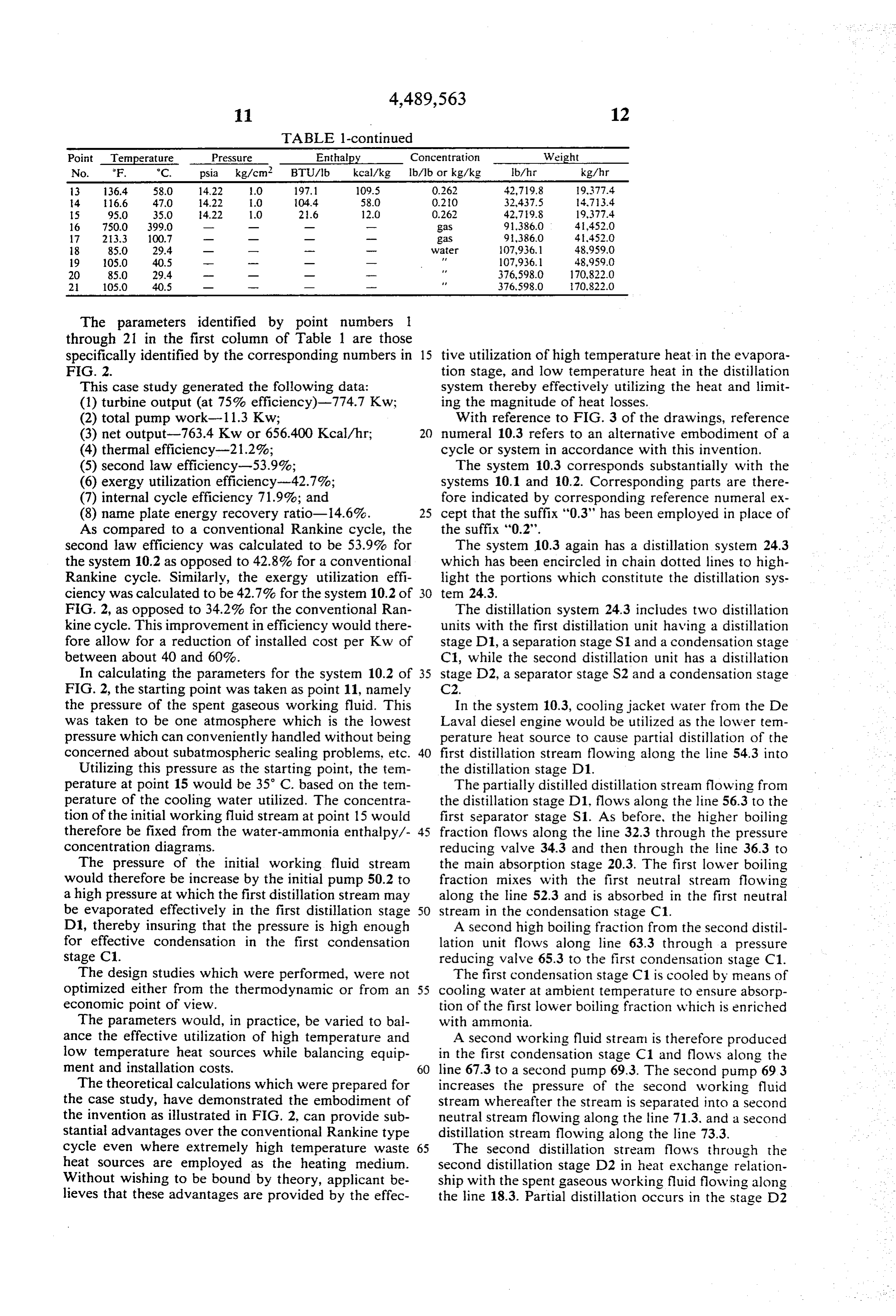
The parameters identified by point numbers 1 through 21 in the first column of Table 1 are those specifically identified by the corresponding numbers in 15 tive utilization of high temperature heat in the evapora FIG. 2. tion stage, and low temperature heat in the distillation This case study generated the following data: system thereby effectively utilizing the heat and limit (1) turbine output (at 75% efficiency)-774.7 Kw; ing the magnitude of heat losses. (2) total pump work-1 1.3 Kw; With reference to FIG. 3 of the drawings, reference (3) net output-763.4 Kw or 656.400 Kcal/hr, 20 numeral 10.3 refers to an alternative embodiment of a (4) thermal efficiency-21.2%; cycle or system in accordance with this invention. (5) second law efficiency-53.9%; The system 10.3 corresponds substantially with the (6) exergy utilization efficiency-42.7%; systems 10.1 and 10.2. Corresponding parts are there (7) internal cycle efficiency 71.9%; and fore indicated by corresponding reference numeral ex (8) name plate energy recovery ratio-14.6%. 25 cept that the suffix "0.3" has been employed in place of As compared to a conventional Rankine cycle, the the Suffix "0.2'.
second law efficiency was calculated to be 53.9% for The system 10.3 again has a distillation system 24.3 the system 10.2 as opposed to 42.8% for a conventional which has been encircled in chain dotted lines to high Rankine cycle. Similarly, the exergy utilization effi light the portions which constitute the distillation sys ciency was calculated to be 42.7% for the system 10.2 of 30 ten 24.3.
FIG. 2, as opposed to 34.2% for the conventional Ran The distillation system 24.3 includes two distillation kine cycle. This improvement in efficiency would there units with the first distillation unit having a distillation fore allow for a reduction of installed cost per Kw of stage D1, a separation stage S1 and a condensation stage between about 40 and 60%. C1, while the second distillation unit has a distillation In calculating the parameters for the system 10.2 of 35 stage D2, a separator stage S2 and a condensation stage FIG. 2, the starting point was taken as point 11, namely C2.
the pressure of the spent gaseous working fluid. This In the system 10.3, cooling jacket water from the De was taken to be one atmosphere which is the lowest Laval diesel engine would be utilized as the lower ten pressure which can conveniently handled without being perature heat source to cause partial distillation of the concerned about subatmospheric sealing problems, etc. 40 first distillation strean flowing along the line 54.3 into Utilizing this pressure as the starting point, the tem the distillation stage D1.
perature at point 15 would be 35 C. based on the tem The partially distilled distillation stream flowing from perature of the cooling water utilized. The concentra the distillation stage D1, flows along the line 56.3 to the tion of the initial working fluid stream at point 15 would first separator stage S1. As before, the higher boiling therefore be fixed from the water-ammonia enthalpy/- 45 fraction flows along the line 32.3 through the pressure concentration diagrams. reducing valve 34.3 and then through the line 36.3 to The pressure of the initial working fluid stream the main absorption stage 20.3. The first lower boiling would therefore be increase by the initial pump 50.2 to fraction mixes with the first neutral stream flowing a high pressure at which the first distillation stream may along the line 52.3 and is absorbed in the first neutral be evaporated effectively in the first distillation stage 50 stream in the condensation stage C1. D1, thereby insuring that the pressure is high enough A second high boiling fraction from the second distil for effective condensation in the first condensation lation unit flows along line 63.3 through a pressure stage C1. reducing valve 65.3 to the first condensation stage C1. The design studies which were performed, were not The first condensation stage C1 is cooled by means of optimized either from the thermodynamic or from an 55 cooling water at ambient temperature to ensure absorp economic point of view. tion of the first lower boiling fraction which is enriched The parameters would, in practice, be varied to bal with ammonia.
ance the effective utilization of high temperature and A second working fluid stream is therefore produced low temperature heat sources while balancing equip in the first condensation stage C1 and flows along the ment and installation costs. 60 line 67.3 to a second pump 69.3. The second pump 69.3 The theoretical calculations which were prepared for increases the pressure of the second working fluid the case study, have demonstrated the embodiment of stream whereafter the stream is separated into a second the invention as illustrated in FIG. 2, can provide sub neutral stream flowing along the line 71.3, and a second stantial advantages over the conventional Rankine type distillation stream flowing along the line 73.3. cycle even where extremely high temperature waste 65 The second distillation stream flows through the heat sources are employed as the heating medium. Second distillation stage D2 in heat exchange relation Without wishing to be bound by theory, applicant be ship with the spent gaseous working fluid flowing along lieves that these advantages are provided by the effec the line 18.3. Partial distillation occurs in the stage D2
Page 13
On the downstream side of the initial pump 50.2, the illustrated in FIG. 2 of the drawings, only the heat initial working fluid stream is separated into a first neu available from the exhaust gas was utilized as a heat tral stream which flows along line 52.2, and a first distil source since the lower temperature heat was not re lation stream which flows along line 54.2. quired.
The distillation system 24.2 includes a first distillation 5 In the embodiment illustrated in FIG. 3, however. stage D1 which is in the form of a heat exchanger to heat available in the form of exhaust gas as well as heat place the first distillation stream flowing along the line available in the form of jacket water was utilized as the 54.2 in heat exchange relationship with spent gaseous heat Source.
working fluid flowing along the line 18.2. The De Laval engine was a model DSRV-12-4 of Relatively lower temperature heat from the spent O Transamerica De Laval, Inc. "Enterprise". It had a gaseous working fluid causes partial distillation of the gross bhp rating of 7,390 and a net bhp rating of 7,313. first distillation stream in the first distillation stage D1 to The available heat sources which could be utilized generate working fluid fractions of differing composi from the waste heat of the De Laval diesel engine are as tions which flow along the line 56.2 to a first separator follows:
stage S1. 15
The first separator stage S1 may be provided by a EXHAUST GAS separator stage of any conventional suitable type known to those skilled in the art. T 750 F. 3.19.9 C. In the separator stage S1 the working fluid fractions T2 H (heat in
become separated into a lower boiling fraction and a exhaust gas20 higher boiling fraction. The higher boiling fraction above 200 F.)
which is impoverished with respect to the ammonia, flows out of the distillation system 24.2 along line 32.2 through the pressure release valve 34.2 and then through the line 36.2 to the main absorption stage 20.2. JACKET WATER The lower boiling fraction which is enriched with T 175° F. 79.44 C. respect to the ammonia flows along line 58.2 and is T2 63 F. 72.78 C. mixed with the first neutral stream flowing along line H 8,440,300 BTU/hr. 2,027.130 Kcal/hr. 52.2 to enrich the first neutral stream. The lower boiling fraction is therefore absorbed in the first neutral stream 30 in a first condensation stage C1 to form a first rich solu tion stream which leaves the first condensation stage LUBRICATING OIL C1. T 75° F. 79.44 C. In the system 10.2, the distillation system 24.2 com H
prises only a single distillation unit. The first rich solu 35 tion stream which leaves the first condensation stage C1 therefore constitutes the main rich solution stream which leaves this distillation system 24.2 along the line EXERGY IN AVAILABLE HEAT SOURCE 26.2 and flows to the main rich solution pump 28.2 Exergy is defined at the initial cooling water tempera where its pressure is increased prior to evaporation in 40 ture of 85 F. and final temperature of 105 F. Exergy in the main evaporation stage 12.2. heat sources having an initial temperature less than 160 In the cycle 10.2, cooling water at ambient tempera F. is considered de minimus and has been ignored. The ture is employed both in the main absorption stage 20.2 exergy in available heat sources is: and in the first condensation stage C1 to effect absorp (a) exhaust gas-1,431.4 Kw or 1,230,607 Kw/hr; tion of gaseous fractions into liquid fractions in these (b) jacket water-277.9 Kw or 238,190 Kcal/hr, two stages. For the relatively higher temperature heat (c) lubrication oil-78.3 Kw or 67,329 Kcal/hr, to effect evaporation of the main rich solution in the (d) total-l,787.5 Kw or 1,536.846 Kcal/hr. main evaporation stage 12.2, exhaust gases from a De In the case study which was performed, the tempera Laval diesel engine is utilized to flow along the line tures, pressures and concentrations were ascertained 4.0.2. from water-ammonia enthalpy/concentration diagrams A case study was prepared to illustrate the recovery which are available in the literature. of waste heat from a De Laval diesel engine. Waste heat The case study which was calculated on the basis of is available from such an engine in the form of exhaust the system 10.2 as illustrated in FIG. 2, had the parame gas, jacket water and lubrication oil. In the embodiment ters as set out below in Table 1.
TABLE 1
Point Temperature Pressure Enthalpy Concentration Weight No. F. °C. psia kg/cm, BTU/lb kcal/kg lb/lb or kg/kg b/hr kg/hr 95.0 35.0 42.67 3.0 2.6 12.0 0.262 42.719.S 19.377.4
S 95.0 35.0 42.67 3.0 1.6 12.0 0.262 7,597. 3.446.0 45.4 63.0 42.67 3.0 22S.-4 26.9 0.426 10,282.4 4.664.0 5 67.) 75.0 42.67 3.0 5S-4 SSO 0.262 35.22.7 5,931.4 6 67.0 750 42.67 3.0 83.6 52.0 O.S90 2.685.2 1.21S.0 7 b70 75.() 4.67 3.0 104.4 58.0 0.210 32437.5 1-4.3.4 S 95.0 35.0 42.6 3.0 19.4 O.S 0.426 0.2S2.4 4.66.4.0 C o50 350 16 50.0 19-4 1O.S 0.426 10.2S2.4 4.664.0 O 662.0 3500 7 6 50.0 112.5 673.6 0.426 10.2S2.4 4.66-4.0 l S.S. S-40 1-4.2 O Q56.9 53. 0.426 10.2S.- 4.6th-4.0 S.O.S 66.() 1-422 1. 489.6 2.0 0.42b O.S.-4 4,664.0
Page 14
TABLE 1-continued
Point Temperature Pressure Enthalpy Concentration Weight No. F. C. psia kg/cm, BTU/lb kcal/kg Ib/lb or kg/kg b/hr kg/hr
4 16.6 47.0 14.22 E.0 04.4 58.0 0.20 32,437.5 4.73.4
16 7500 399.0 -- gas 91.386.0 4i,452.0 17 23.3 100.7 gas 9386.0 4,452.0 18 85.0 29.4 m w --- Water 107,936.1 48,959.0
20 85.0 29.4 --- 376,598.0 170,822.0 2 105.0 40.5 m - 376,598.O 70,822.0
The parameters identified by point numbers 1 through 21 in the first column of Table 1 are those specifically identified by the corresponding numbers in 15 tive utilization of high temperature heat in the evapora FG. 2. tion stage, and low temperature heat in the distillation This case study generated the following data: system thereby effectively utilizing the heat and limit (1) turbine output (at 75% efficiency)-774.7 Kw; ing the magnitude of heat losses. (2) total pump work-1 1.3 Kw; With reference to FIG. 3 of the drawings, reference (3) net output-763.4 Kw or 656.400 Kcal/hr, 20 numeral 10.3 refers to an alternative embodiment of a (4) thermal efficiency-21.2%; cycle or system in accordance with this invention. (5) second law efficiency-53.9%; The system 10.3 corresponds substantially with the (6) exergy utilization efficiency-42.7%; systems 10.1 and 10.2. Corresponding parts are there (7) internal cycle efficiency 71.9%; and fore indicated by corresponding reference numeral ex (8) name plate energy recovery ratio-14.6%. 25 cept that the suffix "0.3" has been employed in place of As compared to a conventional Rankine cycle, the the suffix '0.2'.
second law efficiency was calculated to be 53.9% for The system 10.3 again has a distillation system 24.3 the system 10.2 as opposed to 42.8% for a conventional which has been encircled in chain dotted lines to high Rankine cycle. Similarly, the exergy utilization effi light the portions which constitute the distillation sys ciency was calculated to be 42.7% for the system 10.2 of ten 24.3.
FIG. 2, as opposed to 34.2% for the conventional Ran The distillation system 24.3 includes two distillation kine cycle. This improvement in efficiency would there units with the first distillation unit having a distillation fore allow for a reduction of installed cost per Kw of stage D1, a separation stage S1 and a condensation stage between about 40 and 60%. C1, while the second distillation unit has a distillation In calculating the parameters for the system 10.2 of 35 stage D2, a separator stage S2 and a condensation stage FIG. 2, the starting point was taken as point 11, namely C2.
the pressure of the spent gaseous working fluid. This In the system 10.3, cooling jacket water from the De was taken to be one atmosphere which is the lowest Laval diesel engine would be utilized as the lower ten pressure which can conveniently handled without being perature heat source to cause partial distillation of the concerned about subatmospheric sealing problems, etc. 40 first distillation stream flowing along the line 54.3 into Utilizing this pressure as the starting point, the tem the distillation stage D1.
perature at point 15 would be 35 C. based on the tem The partially distilled distillation stream flowing from perature of the cooling water utilized. The concentra the distillation stage D1 flows along the line 56.3 to the tion of the initial working fluid stream at point 15 would first separator stage S1. As before, the higher boiling therefore be fixed from the water-ammonia enthalpy/- 45 fraction flows along the line 32.3 through the pressure concentration diagrams. reducing valve 34.3 and then through the line 36.3 to The pressure of the initial working fluid stream the main absorption stage 20.3. The first lower boiling would therefore be increase by the initial pump 50.2 to fraction mixes with the first neutral stream flowing a high pressure at which the first distillation stream may along the line 52.3 and is absorbed in the first neutral be evaporated effectively in the first distillation stage 50 stream in the condensation stage C1. D1, thereby insuring that the pressure is high enough A second high boiling fraction from the second distil for effective condensation in the first condensation lation unit flows along line 63.3 through a pressure stage C1. reducing valve 65.3 to the first condensation stage C1. The design studies which were performed, were not The first condensation stage C1 is cooled by means of optimized either from the thermodynamic or from an 55 cooling water at ambient temperature to ensure absorp economic point of view. tion of the first lower boiling fraction which is enriched The parameters would, in practice, be varied to bal with ammonia.
ance the effective utilization of high temperature and A second working fluid stream is therefore produced low temperature heat sources while balancing equip in the first condensation stage C1 and flows along the ment and installation costs. 60 line 67.3 to a second pump 69.3. The second pump 693 The theoretical calculations which were prepared for increases the pressure of the second working fluid the case study, have demonstrated the embodiment of stream whereafter the stream is separated into a second the invention as illustrated in FIG. 2, can provide sub neutral stream flowing along the line 71.3, and a second stantial advantages over the conventional Rankine type distillation stream flowing along the line 73.3, cycle even where extremely high temperature waste 65 The second distillation stream flows through the heat Sources are employed as the heating medium. Second distillation stage D2 in heat exchange relation Without wishing to be bound by theory, applicant be ship with the spent gaseous working fluid flowing along lieves that these advantages are provided by the effec the line 18.3. Partial distillation occurs in the stage D2
Page 15
so that the partially distilled second distillation stream 4. Thermal efficiency-15.2%. flows along the line 75.3 to a second separator stage S2. 5. Second law efficiency-51.9%. The higher boiling fraction from the separator stage S2 6. Exergy utilization efficiency-48.2%. constitutes the second higher boiling fraction which 7. Internal cycle efficiency-69.2%. flows along line 63.3 to the first condensation stage C1. 5 8. Name plate energy recovery ratio-16.5%. The second lower boiling fraction flows along line 77.3 In comparing the theoretical calculation for the cycle and is absorbed into the second neutral stream in the of system 10.3 with that of a conventional Rankine second condensation stage C2. The second condensa- cycle, it was found that the second law efficiency of the tion stage C2 is again cooled with cooling water at cycle 10.3 was 51.9% as opposed to 42.8% for the con ambient temperature. 10 ventional Rankine cycle. It was further calculated that The resultant main rich solution emerges from the the exergy utilization efficiency for the cycle 10.3 was distillation system 24.3 along line 26.3 and enters the 48.2% as opposed to 34.2% for the conventional Ran pump 28.3 where it is pumped to an appropriate pres- kine cycle. This improvement over the cycle 10.2 is sure for complete or substantially complete evaporation believed to be as a result of the more effective utilization in the main evaporation stage 12.3 where it is evapo- 15 of the lower temperature waste heat generated by the rated with exhaust gases from the DeLeval engine. DeLaval diesel engine during use.
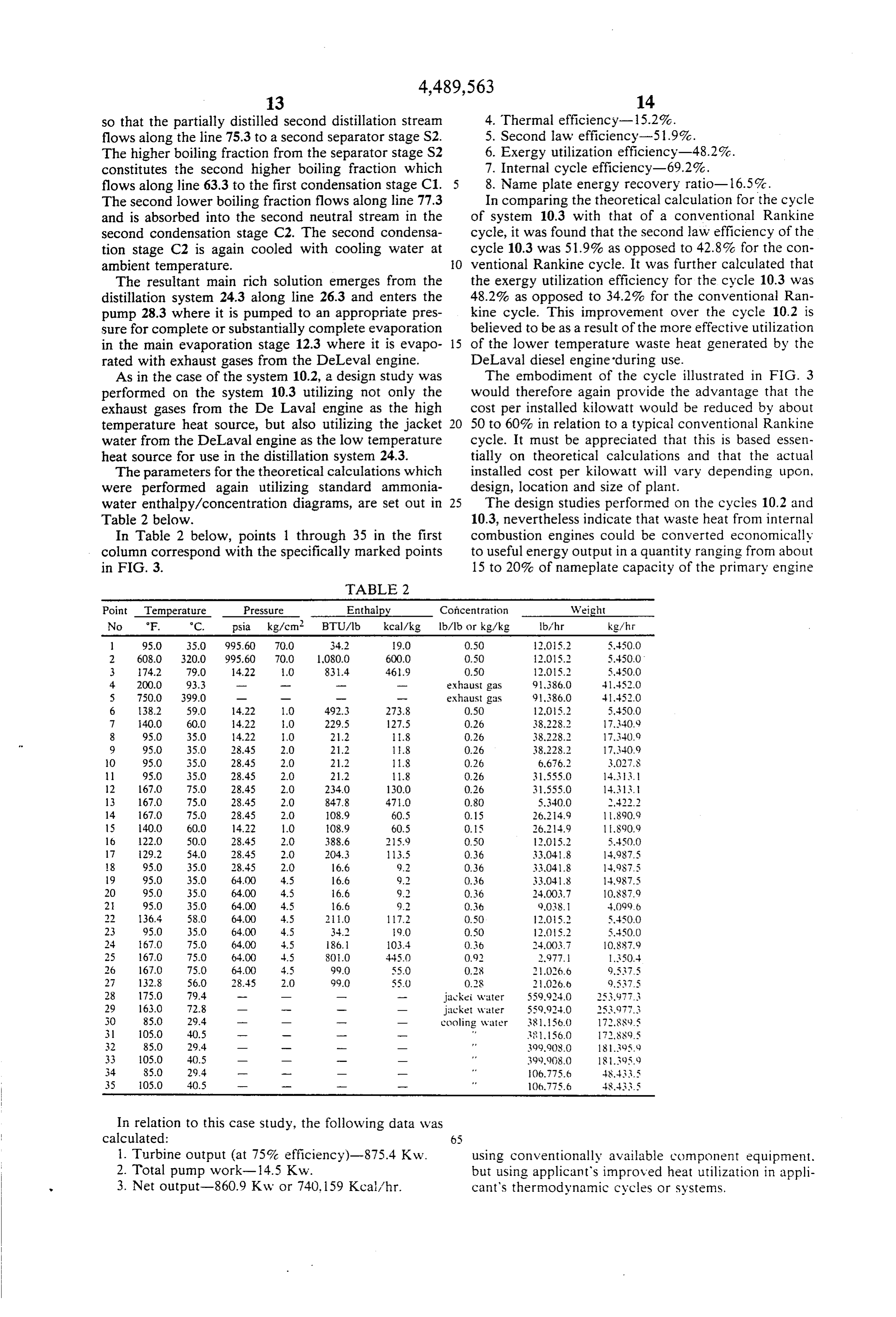
As in the case of the system 10.2, a design study was The embodiment of the cycle illustrated in FIG. 3 performed on the system 10.3 utilizing not only the would therefore again provide the advantage that the exhaust gases from the De Laval engine as the high cost per installed kilowatt would be reduced by about temperature heat source, but also utilizing the jacket 20 50 to 60% in relation to a typical conventional Rankine water from the DeLaval engine as the low temperature cycle. It must be appreciated that this is based essen heat source for use in the distillation system 24.3. tially on theoretical calculations and that the actual The parameters for the theoretical calculations which installed cost per kilowatt will vary depending upon. were performed again utilizing standard ammonia- design, location and size of plant.
water enthalpy/concentration diagrams, are set out in 25 The design studies performed on the cycles 10.2 and Table 2 below. 10.3, nevertheless indicate that waste heat from internal In Table 2 below, points 1 through 35 in the first combustion engines could be converted economically column correspond with the specifically marked points to useful energy output in a quantity ranging from about in FIG. 3. 15 to 20% of nameplate capacity of the primary engine
TABLE 2
Point Temperature Pressure Enthalpy Concentration Weight No F. C. psia kg/cm, BTU/lb kcal/kg b/lb or kg/kg b/hr kg/h F 95.0 35.O. 995.60 70.0 34.2 9.0 0.50 2015.2 5,450.0 2 608.0 320.0 995.60 700 1,080.0 600.0 0.50 2,015. 5,450.O. 3 74.2 79.0 4.22 1.0 83.4 46.9 O.50 2015. 5,450.0 4 2000 93.3 exhaust gas 9,386.0 41.52.0 5 7500 399.0 exhaust gas 9,386.0 4,452.0 6 38.2 59.0 14.22 10 49.3 273.8 OSO 2.05.2 5,450.0 7 40.0 60.0 14.22 E.O 229.5 27.5 0.26 38,228.2 17,340.9 8 95.0 35.0 14.22 O 21.2 8 0.26 38,228. 17,340.9
O 95.0 35.0 28.45 2.0 21.2 1.8 0.26 6,676.2 3.02.8 11 95.0 35.0 28.45 2.0 21.2 8 O.26 31555.0 14.33.
13 167.0. 75.0 28.45 2.0 847.8 470 O.80 5,340.0 2,422.2
15 1400 60.0 14.22 10 O8.9 60.5 0.5 26.24.9 1890.9
18 95.0 35.0 28.45 2.O 16.6 9.2 O.36 33,048 14.9S7.5
20 95.0 350 6400 4.5 16.6 9. O.36 24,003. 10,887.9 2 95.0 35.0 64.00 4.5 6.6 9.2 O.36 9.038. 4,099.6 22 36.4 580 64.OO 4.5 2.0 17.2 0.50 2.05. 5.45.O.O 23 95.0 350 6400 4.5 34.2 9.0 0.50 OS2 5,450.O 24 67.0. 75.0 64.00 4.5 86. 103.4 O.36 2003.7 10,887.9 25 167.O 75.0 64.OO .45 SOO 445.) 0.92 2,977. 50 26 67.0 75.0 64.00 3.5 99.0 55.0 0.8 O6.8 9,535 27 132.8 56.0 28.45 2.0 99.0 55.) O.S. 2,026.6 9,537.5 28 1750 79.4 w jackei water 559,924.O 253.977.3 29 163.O 72.8 - --- m jacket water 559,924.O 253,977.3 30 850 29.4 --- cooling water 381.156.0 17.SSl).5 31 105.0 40.5 --- r 3856.0 7.889.5 32 85.0 29.4 ww. 399,908.O 18395.9 33 05.0 40.5 - - --- 399,908.O 8.395.9 34 S5.0 29.4 -- 1- O6.775.6 48.43.5 35 05.0 40.5 --- 106.775.6 48-4
In relation to this case study, the following data was calculated: 65 1. Turbine output (at 75% efficiency)-875.4 Kw. using conventionally available component equipment. 2. Total pump work-14.5 Kw. but using applicant's improved heat utilization in appli 3. Net output-860.9 Kw or 740,159 Kcal/hr. cant's thermodynamic cycles or systems.
Page 16
With reference to FIG. 4 of the drawings, reference prising main distillation stages D1 and D2, main con numeral 10.4 refers generally to yet a further alternative densation stages C1 and C2, and a plurality of separa embodiment in accordance with this invention. tion stages S1, S2 and S3.
The system 10.4 corresponds generally with the sys A design calculation was performed upon the system tem 10.1. Corresponding parts are therefore indicated 5 10.5 utilizing exhaust gas, jacket water and lubricating by corresponding reference numerals except that the oil from a DeLaval diesel engine as available: heat suffix "0.4" has been employed in place of the suffix sources. This design calculation provided a calculated "0.1'. second law efficiency of 52.6% as opposed to a second The cycle or system 10.4 would be utilized where the law efficiency for a conventional rankine cycle of waste heat source available for use, is available at such O 42.8%. It further provided a calculated exergy utiliza a high temperature that it could evaporate the main rich tion efficiency of about 51.8% as opposed to a conven solution even where the pressure of that solution has tional rankine cycle exergy utilization efficiency of been increased to a pressure far in excess of that which 34.2%.
can conveniently be handled by the main evaporator 12 The embodiment of FIG. 5 illustrates how the param or by the turbine 16. 15 eters of the system of this invention may be varied to The cycle 10.4 is therefore designed to utilize such effectively utilize a large range of available heat sources heat in an effective manner without providing pressure ranging from very high temperature available heat to which cannot conveniently be handled by the evapora low temperature available heat.
tor and turbine. For each application of the invention, available heat In the system 10.4, the distillation system 24.4 pro 20 sources will have to be balanced against specific equip duces, as before, a lean solution which emerges from the ment costs, to arrive at the most appropriate parameters distillation system 24.4 and flows along line 32.4, for each application utilizing appropriate multicompo through pressure reducing valve 34.4, along line 36.4 nent diagrams for the particular working fluid em and into the main absorption stage 20.4. ployed.
In addition, however, the distillation system 24.4 25 The embodiments of the invention as illustrated in the produces two rich solution streams having differing drawings, indicate that the invention can effectively compositions. The one rich solution liquid stream utilize a plurality of different temperature heat sources which is the least enriched with the low boiling ammo to produce energy thereby providing for effective heat nia, and is therefore a higher boiling solution than the utilization and reduced heat loss. remaining rich solution, is fed along line 26.4 to the 30 Further calculations have been done with the system pump 28.4 and is evaporated in the main evaporation in accordance with applicant's invention as compared stage 12.4 using the very high temperature available to a conventional rankine system. With a typical system heat source. The evaporated charged gaseous working in accordance with this invention, applicant found a medium produced in the main evaporation stage 12.4 is second law efficiency of 59.7% as opposed to a second fed through a first turbine 6.4 to release energy therein. 35 law efficiency of 29.7% for a typical rankine cycle The second rich solution liquid stream which is pro when utilizing surface ocean water and deep ocean duced in the distillation system 24.4, and which is more water as the heating and cooling mediums for a typical enriched with the low boiling ammonia and is therefore ocean thermal energy conversion system. a lower boiling fluid than the other rich solution stream, In further calculations performed on a heat source in flows along line 27.4 to a pump 29.4 where its pressure 40 the form of a solar pond, applicant calculated a second is increased. From there it flows along line 80.4 through law efficiency for applicant's invention of about 80% a preheater 82.4 where it flows in heat exchange rela and an exergy utilization efficiency of about 80% as tionship with the spent working fluid from the turbine compared to a second law efficiency and an exergy 16.4. Thereafter it flows along line 84.4 into a second utilization efficiency of a typical Rankine cycle of about main evaporation stage 13.4 where it is evaporated with 45 56%.
slightly lower temperature high temperature heat With reference to FIG. 6 of the drawings, FIG. 6 which is recovered from the main evaporation stage indicates a typical cycle in accordance with applicant's 12.4, to evaporate it. Since it is more enriched with low invention employed for utilizing waste heat in the form boiling ammonia than the remaining rich solution of geothermal heat.
stream, it can be evaporated effectively utilizing a lower 50 The embodiment of FIG. 6 corresponds essentially temperature heat source than utilized in the main evapo with the embodiment of FIG. 2. Corresponding parts ration stage 12.4. have therefore been indicated by corresponding refer The evaporation stage 13.4 therefore produces a sec ence numerals except that the suffix "0.6" has been used Ond charged working fluid which is fed to a second in place of the suffix "0.2".
turbine 17.4 to release energy. This spent working fluid The system or cycle 10.6 was designed on a theoreti flows with the spent working fluid from the turbine 16.4 cal basis for utilization of a heat source in the form of to the main absorption stage 20.4 for absorption in the geothermal heat from a site in the United States known lean solution. as the East Mesa geothermal site. The one rich solution stream which flows along the The relatively high temperature heat is fed to the line 26.4 may, in an embodiment of the invention, have 60 main evaporation stage 12.6 as indicated by reference the same composition as the stream which leaves the numeral 40.6 in the form of a hot geothermal brine absorption stage 20.4 depending upon the available heat solution which cools from 335 F. (168.3 C.) to 134.8 Source and the operating conditions. F. (56.0° C.).
The system 10.4 is set out in more detail in FIG. 5 and The cycle 10.6 includes a single distillation unit is identified therein by reference numeral 10.5. which includes two partial distillation stages D1 and The distillation system 24.5 is again identified by D2.
being encircled with chain dotted lines. The distillation The relatively lower temperature heat for the distilla System 24.5 includes a plurality of distillation units com tion system is provided by the spent gaseous working
Page 17
fluid which flows along line 18.6 and passes through the causing partial distillation of portion of the initial work distillation stage D2. Thereafter, the higher boiling ing fluid stream to achieve effective enrichment thereof. fraction from the separator S1joins this flow where line Applicant believes that by having working fluids of 36.6 joins the line 18.6. This combined flow thereafter markedly different composition in the evaporation stage flows in heat exchange relationship with the first distil 5 and in the main absorption stage, effective evaporation lation stream through the partial distillation heat ex and heat utilization can be achieved in the evaporation changer D1. stage for effective and complete evaporation of an en As in the prior systems, the expansion of the charged riched portion of a working fluid. Thereafter by utiliz working fluid across the turbine 16.6 is controlled to ing a substantially impoverished fluid in the main ab achieve a reduced pressure corresponding to the pres 10 sorption stage, the spent working fluid can be effec sure to which the pressure of the lean solution is re tively condensed and thus regenerated for reuse.
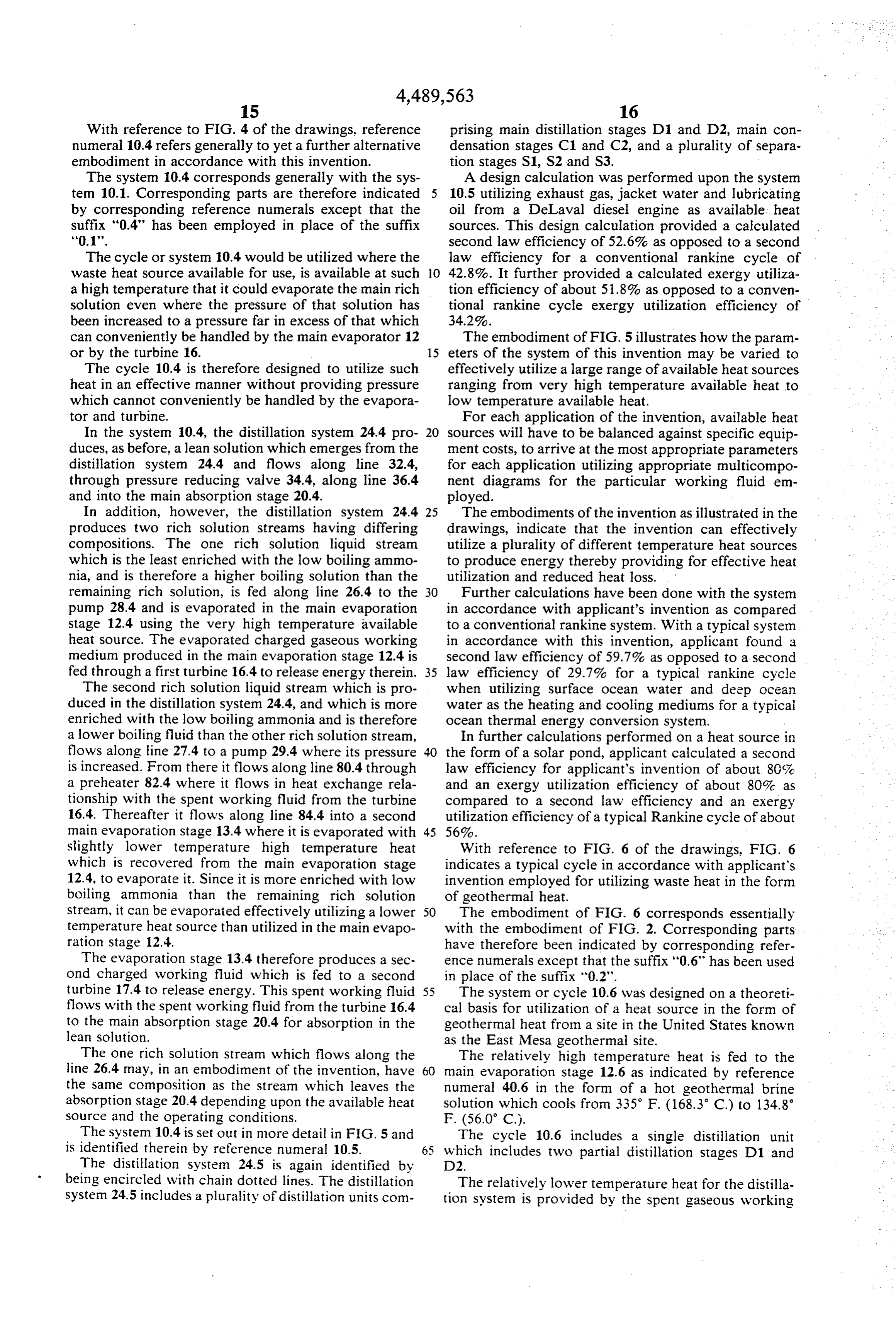
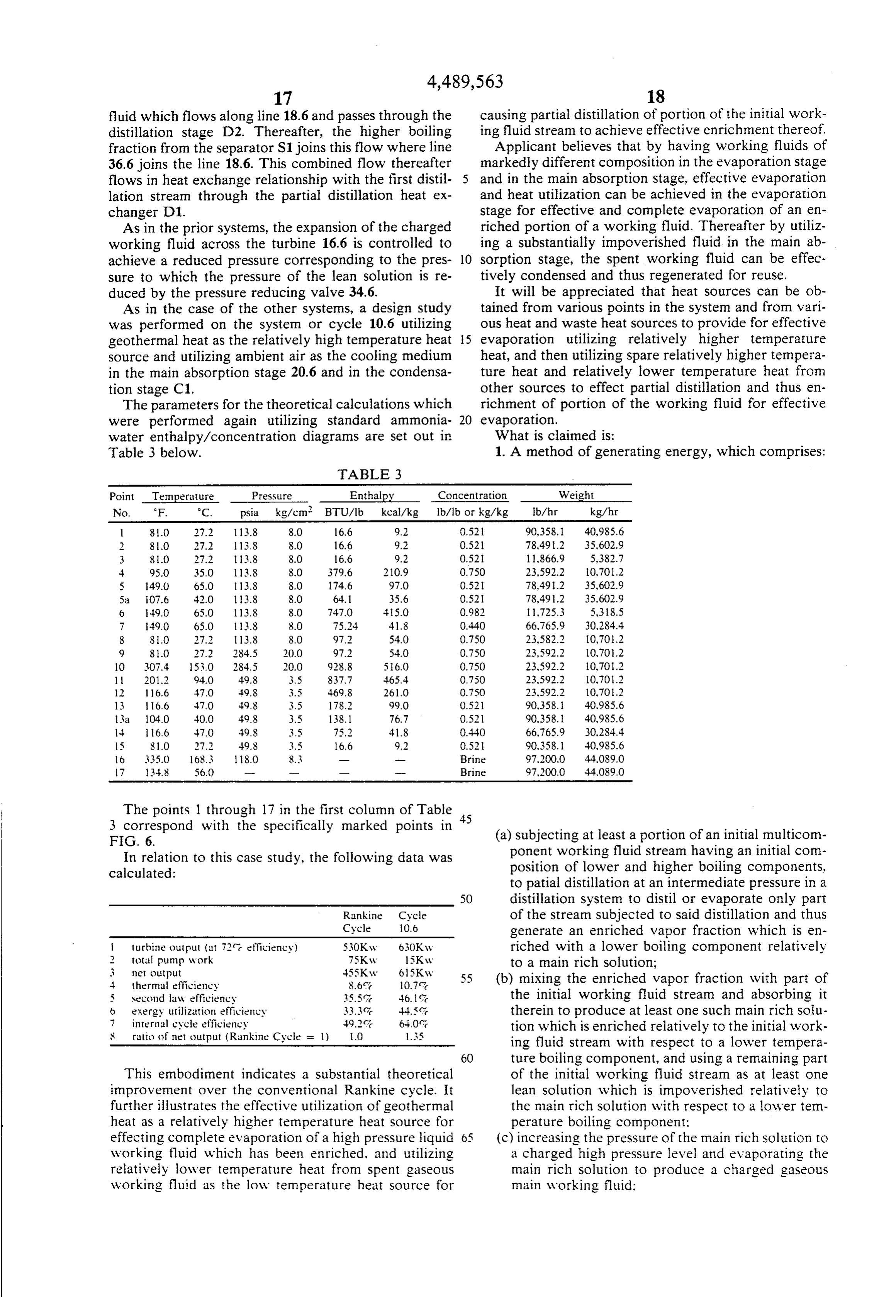
duced by the pressure reducing valve 34.6. It will be appreciated that heat sources can be ob As in the case of the other systems, a design study tained from various points in the system and from vari was performed on the system or cycle 10.6 utilizing ous heat and waste heat sources to provide for effective geothermal heat as the relatively high temperature heat 5 evaporation utilizing relatively higher temperature source and utilizing ambient air as the cooling medium heat, and then utilizing spare relatively higher tempera in the main absorption stage 20.6 and in the condensa ture heat and relatively lower temperature heat from tion stage C1. other sources to effect partial distillation and thus en The parameters for the theoretical calculations which richment of portion of the working fluid for effective were performed again utilizing standard ammonia 20 evaporation.
water enthalpy/concentration diagrams are set out in What is claimed is:
Table 3 below. 1. A method of generating energy, which comprises:
TABLE 3
Point Temperature Pressure . . Enthalpy Concentration Weight No. F. °C. psia kg/cm, BTU/lb kcal/kg b/lb or kg/kg b/hr kg/hr l 81.0 27.2 113.8 8.0 16.6 9.2 0.52 90,358.1 40,985.6
5;a iO7.6 42.0 13.8 8.0 64.1 35.6 0.521 78.49.2 35.602.9
3a 104.0 30.0 49.8 3.5 138.1 76.7 0.521 90.358. 40,985.6
16 335.0 68.3 8.0 8.3 - - Brine 97.200.0 44,089.0 7 34.8 56.0 - - -- Brine 97.200.0 44,089.0
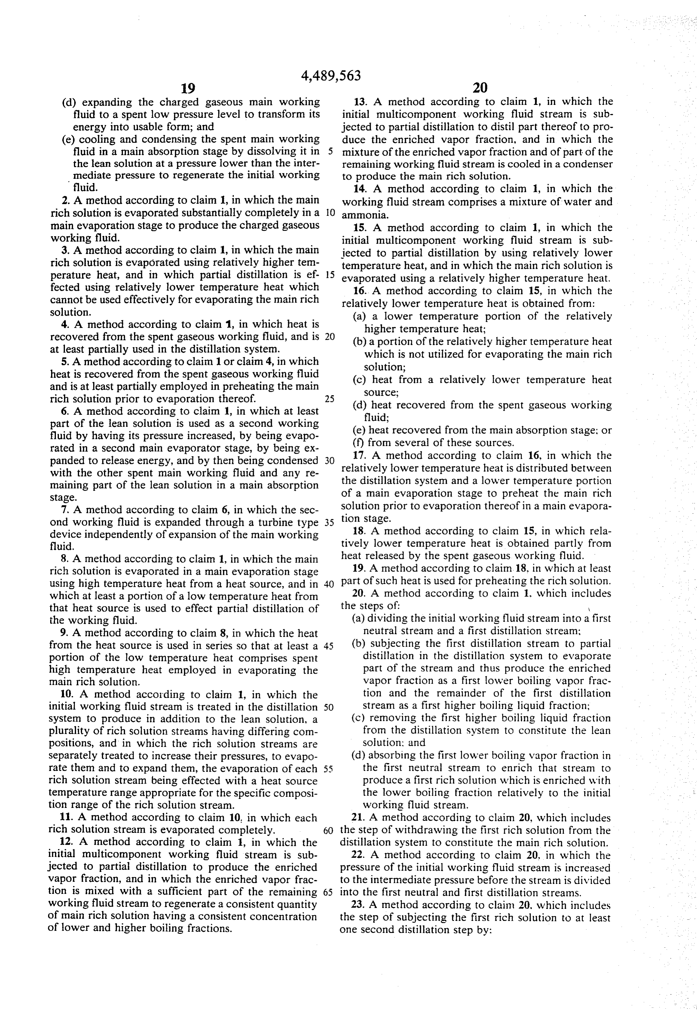
The points 1 through 17 in the first column of Table 3 correspond with the specifically marked points in 45 (a) subjecting at least a portion of an initial multicom
In relation to this case study, the following data was ponent working fluid stream having an initial com calculated: position of lower and higher boiling components, to patial distillation at an intermediate pressure in a 50 distillation system to distill or evaporate only part
Rankine Cycle of the stream Subjected to said distillation and thus
Cycle O.6 generate an enriched vapor fraction which is en 1 turbine output (at 72 efficiency) 530Kw 630Kw riched with a lower boiling component relatively 2 total pump work 7SKw 1SKw to a main rich solution; 3 net output 455Kw 615Kw 4 thermal efficiency 8.6 0.7c 55 (b) mixing the enriched vapor fraction with part of 5 second law efficiency 35.5 ?. 46. the initial working fluid stream and absorbing it 6 exergy utilization efficiency 33.3 c. 4-4.5 therein to produce at least one such main rich solu 7 internal cycle efficiency 49.2 640?. tion which is enriched relatively to the initial work 8 ratic) of net output (Rankine Cycle = 1) 1.0 SS ing fluid stream with respect to a lower tempera 60 ture boiling component, and using a remaining part
This embodiment indicates a substantial theoretical of the initial working fluid stream as at least one improvement over the conventional Rankine cycle. It lean solution which is impoverished relatively to further illustrates the effective utilization of geothermal the main rich solution with respect to a lower tem heat as a relatively higher temperature heat source for perature boiling component: effecting complete evaporation of a high pressure liquid (c) increasing the pressure of the main rich solution to working fluid which has been enriched, and utilizing a charged high pressure level and evaporating the relatively lower temperature heat from spent gaseous main rich solution to produce a charged gaseous working fluid as the low temperature heat source for main working fluid:
Page 18
(d) expanding the charged gaseous main working 13. A method according to claim 1, in which the fluid to a spent low pressure level to transform its initial multicomponent working fluid stream is sub energy into usable form; and jected to partial distillation to distill part thereof to pro (e) cooling and condensing the spent main working duce the enriched vapor fraction, and in which the fluid in a main absorption stage by dissolving it in mixture of the enriched vapor fraction and of part of the the lean solution at a pressure lower than the inter remaining working fluid stream is cooled in a condenser mediate pressure to regenerate the initial working to produce the main rich solution.
fluid. 14. A method according to claim 1, in which the 2. A method according to claim 1, in which the main working fluid stream comprises a mixture of water and rich solution is evaporated substantially completely in a O ammonia.
main evaporation stage to produce the charged gaseous 15. A method according to claim 1, in which the working fluid. initial multicomponent working fluid stream is sub 3. A method according to claim 1, in which the main jected to partial distillation by using relatively lower rich solution is evaporated using relatively higher ten temperature heat, and in which the main rich solution is perature heat, and in which partial distillation is ef 15 evaporated using a relatively higher temperature heat. fected using relatively lower temperature heat which 16. A method according to claim 15, in which the cannot be used effectively for evaporating the main rich relatively lower temperature heat is obtained from: solution. (a) a lower temperature portion of the relatively 4. A method according to claim 1, in which heat is higher temperature heat;
recovered from the spent gaseous working fluid, and is (b) a portion of the relatively higher temperature heat at least partially used in the distillation system. which is not utilized for evaporating the main rich 5. A method according to claim 1 or claim 4, in which solution;
heat is recovered from the spent gaseous working fluid (c) heat from a relatively lower temperature heat and is at least partially employed in preheating the main Source;
rich solution prior to evaporation thereof. 25 (d) heat recovered from the spent gaseous working 6. A method according to claim 1, in which at least fluid;
part of the lean solution is used as a second working (e) heat recovered from the main absorption stage; or fluid by having its pressure increased, by being evapo (f) from several of these sources. rated in a second main evaporator stage, by being ex 17. A method according to claim 16, in which the panded to release energy, and by then being condensed 30 relatively lower temperature heat is distributed between with the other spent main working fluid and any re the distillation system and a lower temperature portion maining part of the lean solution in a main absorption
Stage. of a main evaporation stage to preheat the main rich 7. A method according to claim 6, in which the sec solution prior to evaporation thereof in a main evapora ond working fluid is expanded through a turbine type 35 tion stage.
device independently of expansion of the main working 18. A method according to claim 15, in which rela fluid. tively lower temperature heat is obtained partly from 8. A method according to claim 1, in which the main heat released by the spent gaseous working fluid. rich Solution is evaporated in a main evaporation stage 19. A method according to claim. 18, in which at least using high temperature heat from a heat source, and in 40 part of such heat is used for preheating the rich solution. which at least a portion of a low temperature heat from 20. A method according to claim . . which includes that heat source is used to effect partial distillation of the steps of: W the working fluid. (a) dividing the initial working fluid stream into a first 9. A method according to claim 8, in which the heat neutral stream and a first distillation stream: from the heat source is used in series so that at least a 45 (b) subjecting the first distillation stream to partial portion of the low temperature heat comprises spent distillation in the distillation system to evaporate high temperature heat employed in evaporating the part of the stream and thus produce the enriched main rich solution. vapor fraction as a first lower boiling vapor frac 10. A method according to claim 1, in which the tion and the remainder of the first distillation initial working fluid stream is treated in the distillation stream as a first higher boiling liquid fraction; System to produce in addition to the lean solution, a (c) removing the first higher boiling liquid fraction plurality of rich solution streams having differing com from the distillation system to constitute the lean positions, and in which the rich solution streams are solution; and
Separately treated to increase their pressures, to evapo (d) absorbing the first lower boiling vapor fraction in rate them and to expand them, the evaporation of each 55 the first neutral stream to enrich that stream to rich solution stream being effected with a heat source produce a first rich solution which is enriched with temperature range appropriate for the specific composi the lower boiling fraction relatively to the initial tion range of the rich solution stream. working fluid stream.
11. A method according to claim 10, in which each 21. A method according to claim 20, which includes rich solution stream is evaporated completely. 60 the step of withdrawing the first rich solution from the 12. A method according to claim 1, in which the distillation system to constitute the main rich solution. initial multicomponent working fluid stream is sub 22. A method according to claim 20, in which the jected to partial distillation to produce the enriched pressure of the initial working fluid stream is increased vapor fraction, and in which the enriched vapor frac to the intermediate pressure before the stream is divided tion is mixed with a sufficient part of the remaining 65 into the first neutral and first distillation streams. working fluid stream to regenerate a consistent quantity 23. A method according to claim 20, which includes of main rich solution having a consistent concentration the step of subjecting the first rich solution to at least of lower and higher boiling fractions. one second distillation step by:
Page 19
(a) mixing with the first rich solution a second higher 29. A method according to claim 28, which includes boiling fraction recycled from a succeeding distilla the step of expanding the charged gaseous working tion stage of the distillation system to produce a fluid to transform its energy into usable form, and of second working fluid stream; condensing the spent working fluid by absorbing it, in (b) increasing the pressure of the second working the presence of a cooling medium, in the remaining part fluid stream to a second higher intermediate pres of the working fluid which has been impoverished with sure; respect to a lower boiling component and which was (c) dividing the second working fluid stream into a not mixed with the enriched vapor fraction. second neutral stream and a second distillation 30. A method according to claim 28 or claim 29, in 10 which the relatively higher temperature heat is obtained
Stream;
(d) subjecting the second distillation stream to partial from an available heat source, and in which the rela distillation in the distillation system to distill or tively lower temperature heat comprises spent rela evaporate part thereof and thus produce a second tively higher temperature heat.
lower boiling vapor fraction, and to produce the 15 31. A method according to claim 30, in which the second higher boiling liquid fraction which is recy relatively lower temperature heat further comprises cled and mixed with the first rich solution; and heat extracted from the cycle, which cannot be effec (e) absorbing the second lower boiling vapor fraction tively used in evaporating the enriched portion of the in the second neutral stream to produce a second working fluid.
rich solution having a greater enrichment of lower 32. A method of generating energy, which comprises: boiling fraction than the first rich solution. (a) feeding an initial multicomponent working fluid 24. A method according to claim 23, which includes stream to a partial distillation system; the step of withdrawing the second rich solution from (b) increasing the pressure of the stream to an inter the distillation system to constitute the main rich solu mediate pressure:
tion. (c) separating the stream into a neutral stream and a 25. A method according to claim 23, which includes distillation stream;
the further step of subjecting the second rich solution to (d) subjecting the distillation stream to partial distilla at least one further partial distillation system step to tion to distill or evaporate part of the distillation produce a subsequent rich solution having yet a greater stream to produce working fluid fractions of differ enrichment than the second rich solution. 30 ing compositions, the one fraction being an en 26. A method according to claim 4, or claim 6, or riched vapor fraction which is enriched with at claim 25, in which the pressure of the working fluid least one lower boiling component relatively to an stream is in each distillation stage increased to an inter enriched liquid stream, and the other fraction being mediate pressure consistent with effective distillation of a lean liquid solution; part of the distillation stream in that stage with the 35 (e) withdrawing the fraction comprising a lean liquid available lower temperature heat source, and consistent solution which is impoverished with respect to a with effective condensation of the lower boiling frac lower boiling component, from the distillation sys tion in the neutral stream with an available cooling tem;
medium in each distillation stage to produce a main rich (f) mixing the fraction comprising an enriched vapor solution which is enriched sufficiently for effective 40 fraction which is enriched with respect to at least evaporation with the relatively higher temperature one lower boiling component, with the neutral heat. stream and condensing it therein by means of a 27. A method according to claim 26, in which the cooling medium to form such an enriched liquid main rich solution is pumped to the highest pressure Strean:
consistent with complete evaporation with the available 45 (g) increasing the pressure of the enriched liquid higher temperature heat source and with the capacity of Stream; - expansion means for expanding the gaseous working (h) substantially evaporating the enriched liquid fluid. stream in an evaporation stage to produce a 28. A method of improving the heat utilization effi charged working fluid vapor:
ciency in a thermodynamic cycle using a multicompo 50 (i) expanding the charged working fluid vapor to nent working fluid having components of lower and transform its energy into usable form and produce higher boiling point, which method comprises: a spent working fluid; and (a) utilizing relatively lower temperature heat to ef. (j) mixing the spent working fluid with the lean liquid fect partial distillation of the working fluid by dis Solution and condensing it therein in an absorption tilling or evaporating part of the working fluid to 5 5 stage to regenerate the initial working fluid stream. produce an enriched vapor fraction which is en 33. A method according to claim 32, which comprises riched with respect to the lower boiling component reducing the pressure of the lean liquid solution to a or components relatively to a main rich solution: starting pressure corresponding with that of the spent (b) mixing the enriched vapor fraction with only part vapor before mixing them.
of the remaining working fluid, and condensing the 60 34. A method according to claim 32 or claim 33, in mixture to form such a main rich solution which is which the enriched liquid stream is evaporated using enriched with the lower boiling component rela relatively higher temperature heat, and in which the tively to the working fluid: distillation Stream is partially distilled using relatively (c) increasing the pressure of the main rich solution lower temperature heat.
and then utilizing relatively higher temperature 35. A method according to claim 32, in which the heat to evaporate the main rich solution to produce working fluid comprises a binary fluid of water and a charged gaseous working fluid for expansion to ammonia.
transform its energy into usable form. 36. A method of producing energy, which comprises:
Page 20
(a) feeding an initial multicomponent working fluid cooling means to produce an enriched liquid stream to a partial distillation system at an initial stream;
pressure; (f) increasing the pressure of the enriched liquid (b) increasing the pressure of the initial working fluid stream to a charged pressure; stream to an intermediate pressure; (g) evaporating the enriched liquid stream using a (c) partially distilling the stream by means of rela relatively higher temperature heat to produce a tively lower temperature heat to distill or evaporate charged vapor;
off part of the stream and thus produce at least one (h) expanding the charged vapor to transform its impoverished working fluid stream liquid fraction O energy into usuable form and produce a spent working fluid; and which is impoverished with respect to a lower (i) absorbing the spent working fluid in the portion of boiling component, and at least one enriched vapor the working fluid stream fed to the absorption fraction which is enriched with the lower boiling stage with the aid of a cooling medium to regener component relatively to an enriched liquid stream; ate the initial working fluid stream. (d) withdrawing part of the working fluid stream, 15 37. A method according to claim 36, in which a plu reducing its pressure to the initial pressure, and rality of successive partial distillation steps are per feeding it to an absorption stage; formed to successively increased enrichment and to (e) absorbing the enriched vapor fraction in a remain produce a main enriched : k liquid six k stream.
ing part of the working fluid stream with the aid of
Page 21
UNITED STATES PATENT AND TRADEMARK OFFICE
CERTIFICATE OF CORRECTION
INVENTOR(S) : Alexander I. Kalina
It is certified that error appears in the above-identified patent and that said Letters Patent is hereby Corrected as shown below:
Column l8, line 49, delete "patial" and insert in lieu thereof
Column l8, line 51, delete "said" and insert in lieu thereof
Column 2l, line 31, delete "4, or claim 6" and insert in
eigned and Sealed this
Ninth Day of July 1985
SEAL
Attest:
DONALD J. QUIGG
Attesting Officer Acting Commissioner of Patents and Trademarks
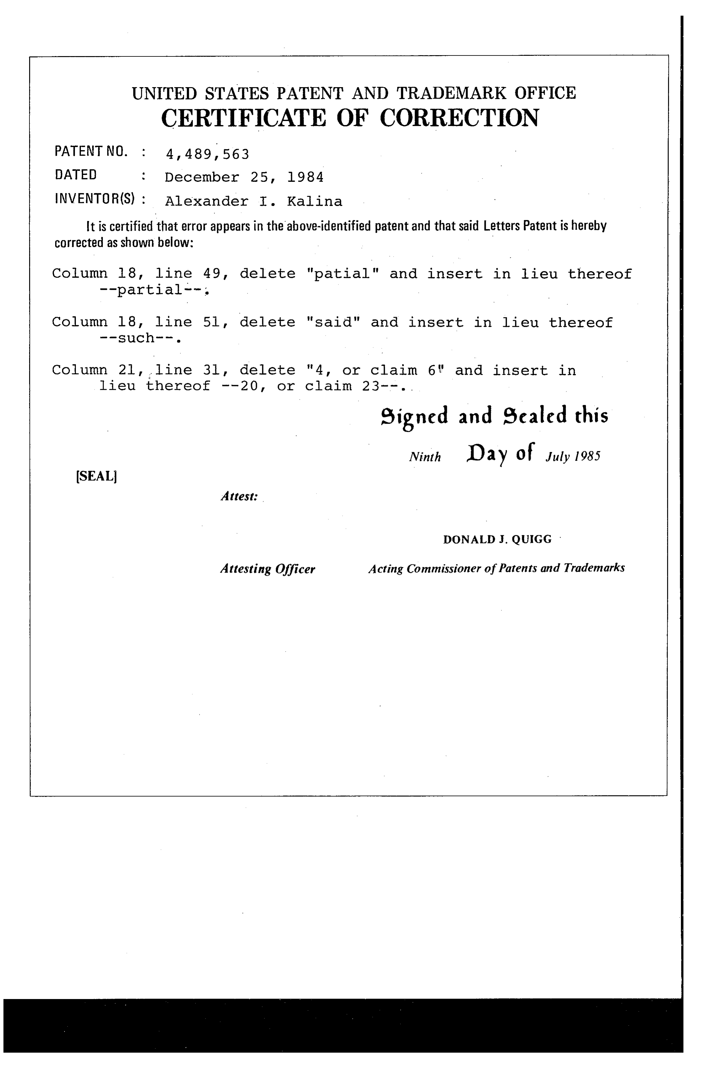
Page 22
UNITED STATES PATENT AND TRADEMARK OFFICE
CERTIFICATE OF CORRECTION
INVENTOR(S) : Alexander I. Kalina
It is certified that error appears in the above-identified patent and that said Letters Patent is hereby Corrected as shown below:
Column 1, line 3, insert --The United States Government has rights in the invention pursuant to an Agreement between the United States Department of Energy and Exergy Power, Inc. (wholly owned subidiary of Exergy, Inc.), successor to Kalina Technologies, Ltd., under Contract No. DE-ACO3 76SFOO700 for operation of the Exergy Technology Engineering Center (ETEC). --
Signed and Sealed this
Twenty-eighth Day of December, 1993
BRUCE LEHMAN
Attesting Officer Commissioner of Patents and Trademarks
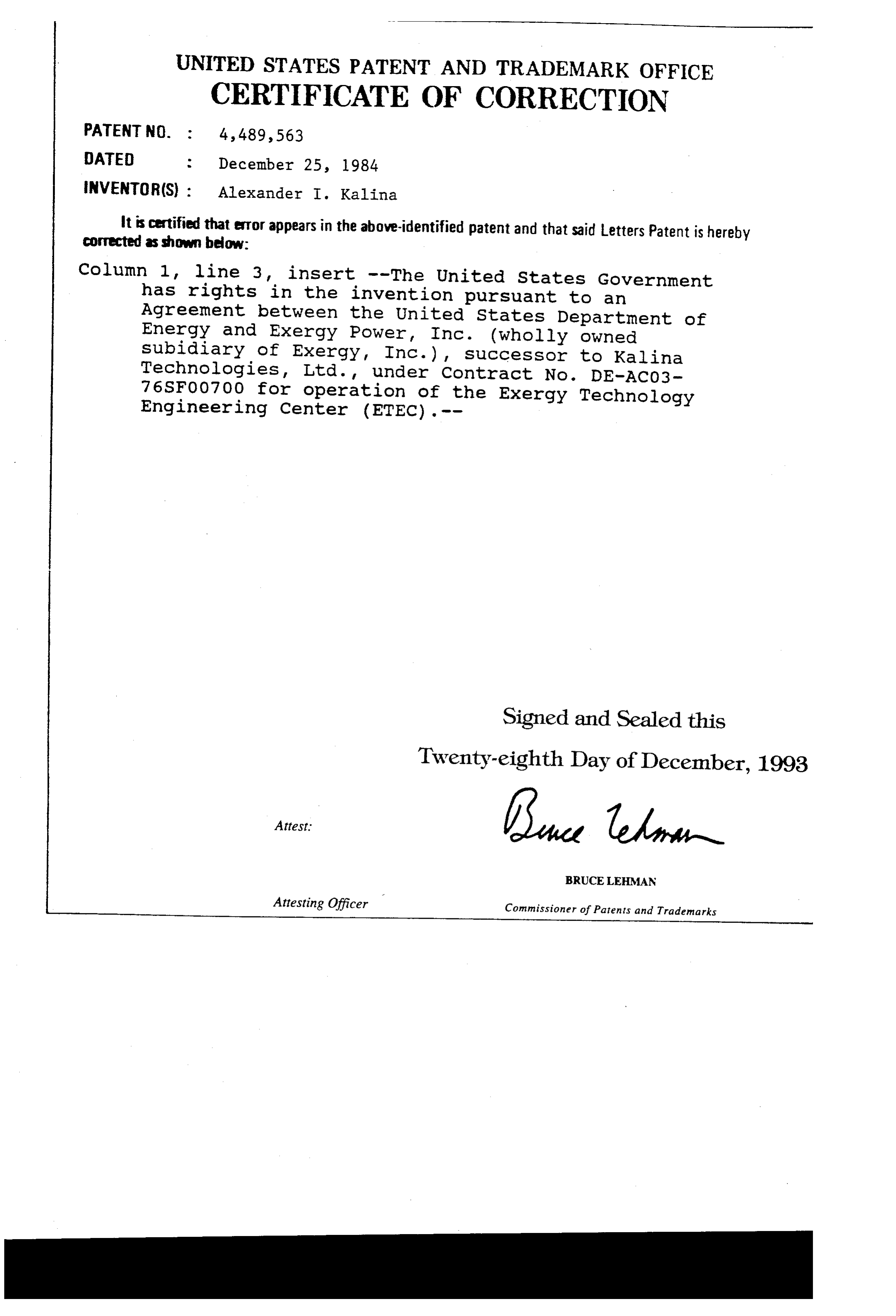
Provenance
- Collection
- Cited prior art
- Original PDF
- patentimages.storage.googleapis.com →
- Filed
- 1982-08-06
- Pages
- 22
- Method
- pdftotext (the PDF's own text layer) + pdftoppm 300dpi page scans
- Source
- Google Patents bibliographic record
- Granted
- 1984-12-25
- Inventors
- Alexander I. Kalina
- Transcribed from
- patentimages.storage.googleapis.com →