patent · US4139056
Method of and system for storing heat
13 February 1979
Page 1 — bibliographic record
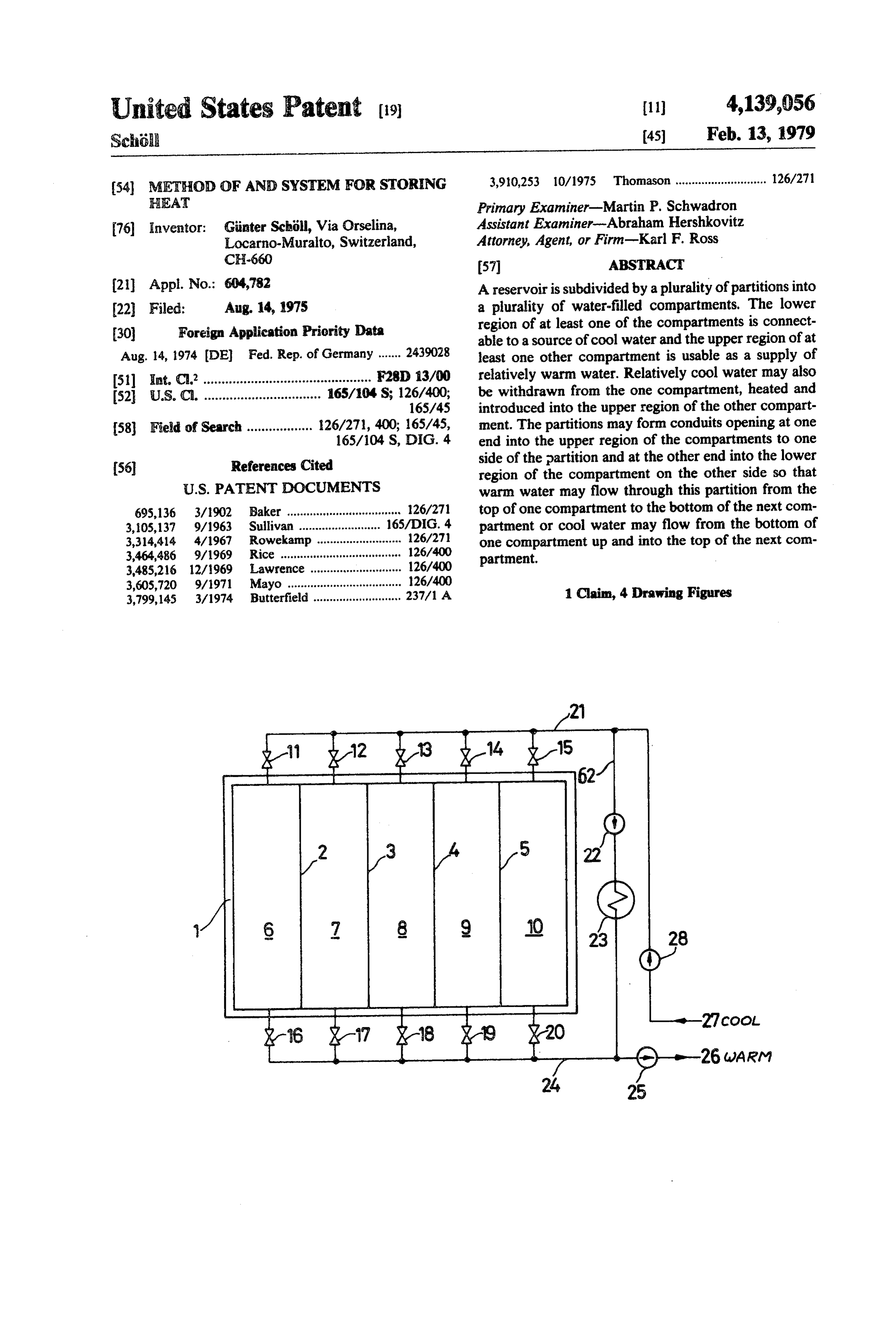
United States Patent (19) 11) 4,139,056 Sch 45 Feb. 13, 1979
(54) METHOD OF AND SYSTEM FOR STORING 3,910,253 10/1975 Thomason ............................ 126/271 HEAT Primary Examiner-Martin P. Schwadron 76 Inventor: Ginter Schöll, Via Orselina, Assistant Examiner-Abraham Hershkovitz Locarno-Muralto, Switzerland, Attorney, Agent, or Firm-Karl F. Ross
CH-660 57 ABSTRACT (21) Appl. No.: 604,782 A reservoir is subdivided by a plurality of partitions into 22 Filed: Aug. 14, 1975 a plurality of water-filled compartments. The lower (30) Foreign Application Priority Data region of at least one of the compartments is connect able to a source of cool water and the upper region of at
Aug. 14, 1974 (DE) Fed. Rep. of Germany ....... 2439028 least one other compartment is usable as a supply of 51) int. C.’.............................................. F28D 13/00 relatively warm water. Relatively cool water may also 52 U.S.C. ................................ 165/104 S; 126/400; be withdrawn from the one compartment, heated and 16S/45 introduced into the upper region of the other compart 58 Field of Search .................. 26/271, 400; 165/45, ment. The partitions may form conduits opening at one 165/104 S, DIG. 4 end into the upper region of the compartments to one (56 References Cited side of the partition and at the other end into the lower region of the compartment on the other side so that
695,136 3/1902 Baker ................................., 26/271 top of one compartment to the bottom of the next com 3,105,137 9/1963 Sullivan ......... 165/DIG. 4 partment or cool water may flow from the bottom of 3,314,414 4/1967 Rowekamp .......................... 126/271 one compartment up and into the top of the next com 3,464,486 9/1969 Rice .......... ... 126/400 partment.
3,485,216 12/1969 Lawrence . ... 126/400 3,605,720 9/1971 Mayo ............ ... 126/400 1 Claim, 4 Drawing Figures 3,799,145 3/1974 Butterfield ........................... 237/1 A
Page 2
Drawing sheet — no readable text.
Page 3
Drawing sheet — no readable text.
Page 4
then it is returned to the lower region of the cool end of
METHOD OF AND SYSTEM FOR STORING HEAT the reservoir.
FIELD OF THE INVENTION
Thus with the system according to the present inven tion the area of the surface between the warm-water
The present invention relates to a system for storing and cool-water layers is reduced considerably. In this heat. More particularly this invention concerns a reser manner the equalization of temperature within the res voir system for holding water whose heat capacity is ervoir is forestalled and, therefore, the warm water used for heat-energy storage. remains at a higher temperature for a longer time so that BACKGROUND OF THE INVENTION the extraction of its heat energy is facilitated.
It is known to store heat energy by means of a large BRIEF DESCRIPTION OF THE DRAWING water-containing vessel or reservoir. The heat of the The above and other objects, features, and advan water in this reservoir is kept in by means of an insulat tages will become more readily apparent from the fol ing cover floating on the reservoir and usually made of lowing, reference being made to the accompanying a synthetic-resin sheet with appropriate flotation. The 15 drawing in which:
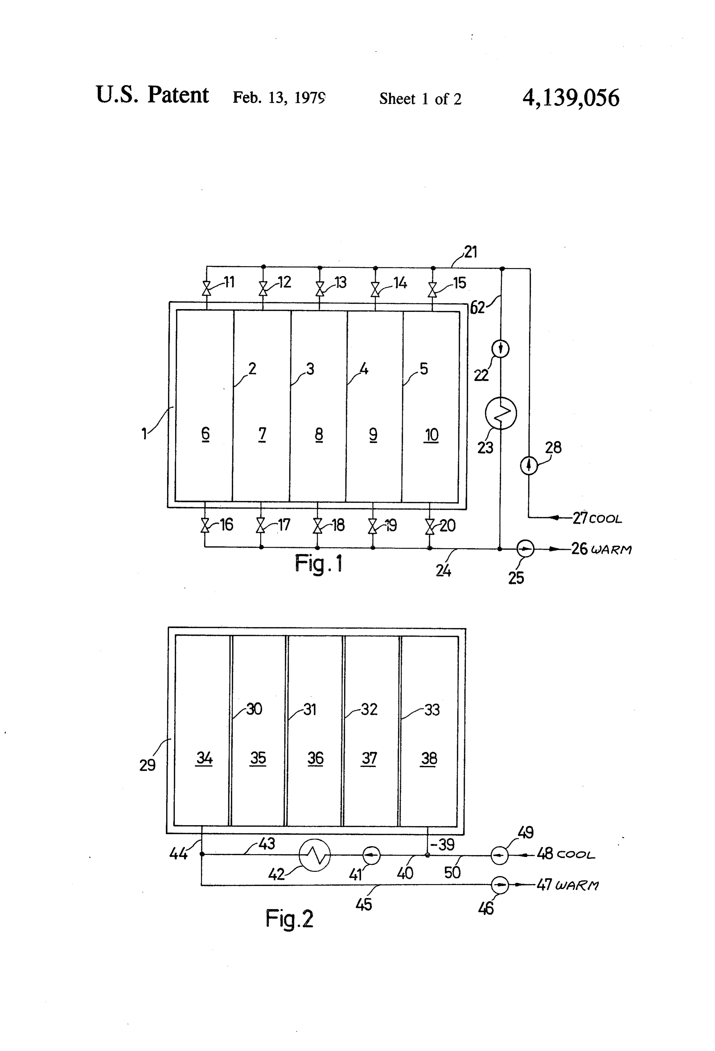
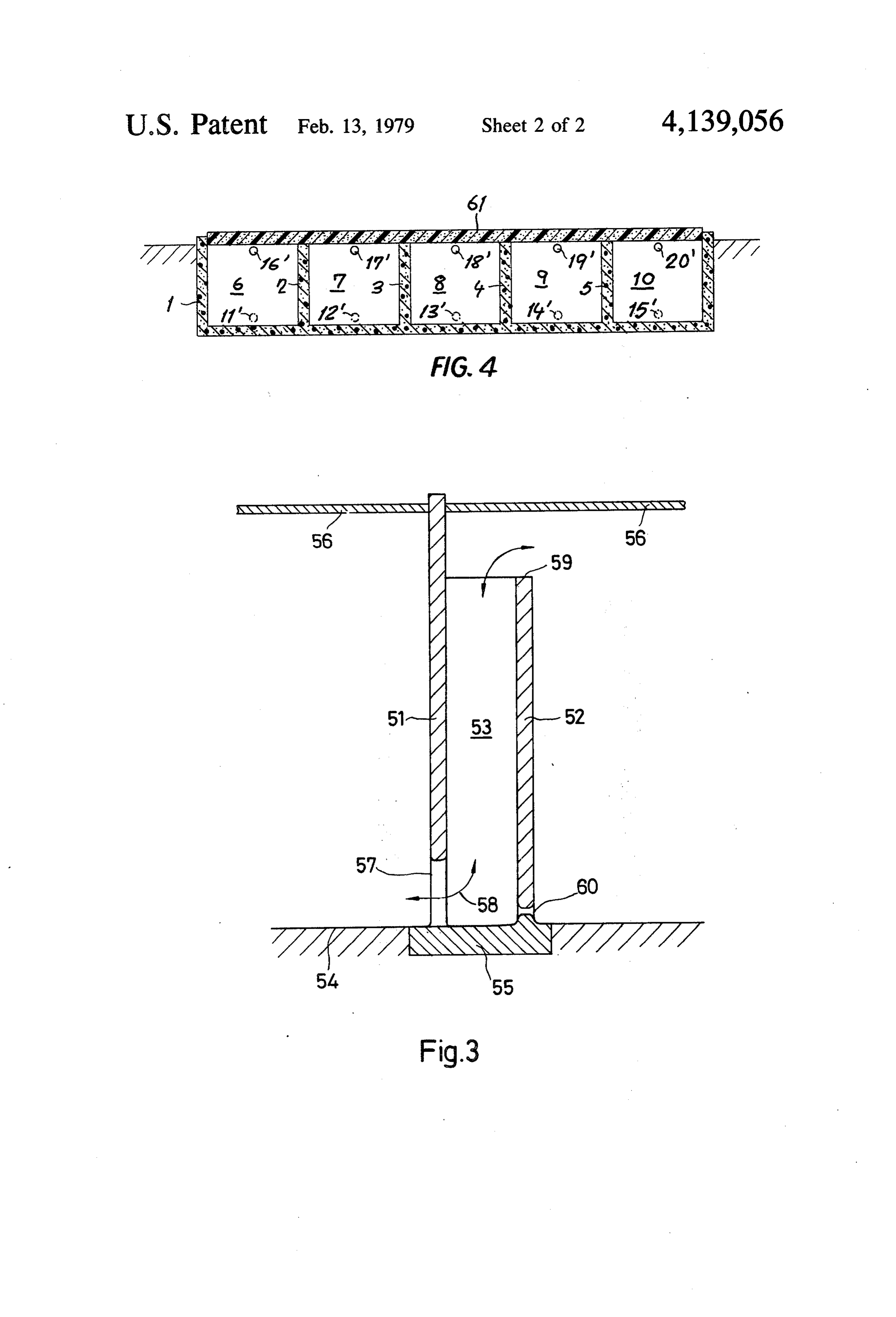
cover prevents the loss of heat to the air and evapora FIGS. 1 and 2 are top schematic views illustrating tion of the water. reservoirs in accordance with this invention, In use cold water is introduced at the bottom of the FIG. 3 is a large-scale vertical section taken through reservoir and hot water may be drained off the top. a detail of the system of FIG. 2, and During the summer or daylight hours hot water may be 20 FIG. 4 is a vertical section through the reservoir of added to the top and cold water removed at the bottom, FIG. 1.
and during the winter or evening hours hot water may be drawn off the top and cold water introduced at the SPECIFIC DESCRIPTION bottom. It is known to circulate the water from the top As shown in FIGS. 1 and 4 a body of water is con to the bottom through a solar heat exchanger or energy 25 tained in a dam or reservoir 1 subdivided by four up collector such as described in my copending patent right partitions 2-5 into five compartments 6-10. An application Ser. No. 488,771 filed July 15, 1974 (now insulating cover 61 overlies the reservoir 1 and prevents abandoned). heat and fluid loss from this reservoir. At the extreme With such a heat-storing system the amount of heat lower region of each of the compartments 6-10 there is energy lost is generally proportional to the area of the 30 upper surface of the body of water. Such losses even in provided trolled by a respective cold-water conduit 11'-15 con a respective valve 11-15 and connected to a the most efficient systems can be relatively high. common cold-water line 21. The top of each of the In such heat-storage systems the water stratifies into layers, with relatively warm water on top and relatively compartments 6-10 is connected to a respective warm cool water underneath. The prior-art arrangements 35 water conduit 16"-20' controlled by a respective valve 16-20 and all connected to a common warm-water line therefore have a large surface between the warm and cool layers, with a corresponding large area for conduc 24. and
A shunt line 62 extends between the lines 21 and 24 is provided with a pump 22 and a heat exchanger tion of heat between the layers. 23. My above-cited copending application describes OBJECTS OF THE INVENTION such a heat exchanger which is usable to heat water by solar energy. In addition the cold water and warm
It is an object of the present invention to provide an water improved method of and system for storing heat. conduits 24 and 21 are provided with respective Another object is an improved reservoir system for pumps 25 and 28 and are connected to respective storing heat energy in water and a method of operating supplies plant, is 26 and 27. A load, such as a household heating connected between the points 26 and 27.
such a reservoir system. 45
With the system shown in FIGS. 1 and 4 heat is
Yet another object is the provision of such a method stored in water during the warm season or sunny hours and system which considerably reduce heat losses.
by opening one of the valves 11-15 and one of the cor
SUMMARY OF THE INVENTION responding valves 16-20 while operating the pump 22 These objects are attained according to the present 50 so as to draw cool water out of the lower region of one invention in a system wherein the reservoir is subdi of the compartments 6-10 and reintroduce it as warm vided by a plurality of upright partitions into a plurality water back into the same compartment at the upper of separate compartments. Means is provided for intro region thereof. During this operation or instead of this ducing or withdrawing relatively warm water into the heating operation it is possible to operate either or both upper region of each of the compartments. 55 of the pumps 25 and 28 so as to pull off or drive off In accordance with the present invention the upper warm water in order to exploit its heat energy. regions of the one end compartment is connected via a The arrangement shown in FIGS. 2 and 3 has a reser conduit to the lower region of the adjoining compart voir 29 provided with four partitions 30–33 subdividing ment so that a temperature gradient exists across the it into five compartments 34-38. Cool water from a reservoir from each compartment to the next, with the source 48 can enter the system through a pump 49 and furthest downstream compartment being the warmest a conduit 50 to an inlet 39 at the bottom of the upstream and the furthest upstream compartment being the coo end compartment 38. Similarly warm water may be lest. During heating periods the water is drawn off from drawn off through a conduit 44 from the top region of the lower part of the cold end of the reservoir, heated, the downstream-end compartment 34 and exit to a load and returned to the upper region of the hot end of the 65 47 through a pipe 45 and a pump 46. A shunt conduit 40 reservoir. When the heat energy in the water is being connects the lines 39 and 50 to a pump 41 and heat exploited the water is drawn off the upper region of the exchanger 42 in turn connected through a shunt conduit hot end of the reservoir, its heat energy is extracted, and 43 to the outlet line 44, 45.
Page 5
The compartments 34-38 are separated from one dimensioned of such small cross-sectional area that it another by like walls as indicated in FIG. 3. A main has virtually no effect on the operation of the reservoir. wall 51 extends from a footing 55 in the base 54 of the I claim:
reservoir all the way up through the cover 56 on the 5 a1.large A system for storing heat, said system comprising: reservoir adapted to hold a body of water for reservoir and is formed adjacent its base with a horizon storage of heat in one season and release at another tally elongated opening 57. Another wall 52 is provided season;
adjacent and parallel to the wall 51 and terminates at its an insulating cover over said water in said reservoir, upper end 59 well below the cover 56 and the upper said cover preventing the loss of heat from said surface of the body of water on which this cover floats. 10 water in said reservoir at the top of said body of This wall 52 defines with the wall 50 a vertical conduit water;
53 starting at the opening 57 and terminating at the a plurality of upright partitions in said reservoir sub upper edge 59 so that water may pass between adjoining dividing same into a plurality of separate compart compartments as is indicated by arrow 58. A small hole ments;
60 is provided adjacent the base of the wall 52 in order 15 means opening into the lower region of each com to allow the reservoir to be completely drained. partment for introducing relatively cool water into With the system of FIGS. 2 and 3 a temperature and withdrawing same from said compartment; gradient exists between each of the compartments 34-38 conduit means opening into the upper region of each and the adjoining compartments. Thus the water in the of said compartments for introducing relatively compartment 38 will be substantially cooler than that in 20 warm water into and withdrawing same from said compartment 37, which itself is substantially cooler compartments;
than that in compartment 36, and so on, with the water a heat exchanger in said conduit means externally of in compartment 34 being the warmest in the reservoir. said reservoir for introducing warm water into said This arrangement greatly facilitates the exploitation of 25 compartments;
the heat stored in the water, since only the warmest a cool-water conduit and a plurality of valves each water in the warmest compartment is employed, connected to a respective compartment and to said means for introducing and for withdrawing said thereby allowing the user to operate with maximum cool water; and efficiency using the greatest possible temperature differ a warm-water conduit and a plurality of valves each ential. In addition the heat loss from overlying layers to 30 connected to a respective compartment and consti underlying layers due to conduction through the water tuting said conduit means, the cold and warm is minimized by reducing the cross-sectional area of the water conduits opening into the respective com column of water being used, since the reservoir 29 ef partments through the respective valves on oppo fectively is holding a column of water having a height site sides of said reservoir.
equal to five times the reservoir depth. The hole 60 is 35
Provenance
- Collection
- Cited prior art
- Original PDF
- patentimages.storage.googleapis.com →
- Filed
- 1975-08-14
- Pages
- 5
- Method
- pdftotext (the PDF's own text layer) + pdftoppm 300dpi page scans
- Source
- Google Patents bibliographic record
- Granted
- 1979-02-13
- Inventors
- Gunter Scholl
- Transcribed from
- patentimages.storage.googleapis.com →