patent · US4397152
Solar furnace
9 August 1983
Page 1 — bibliographic record
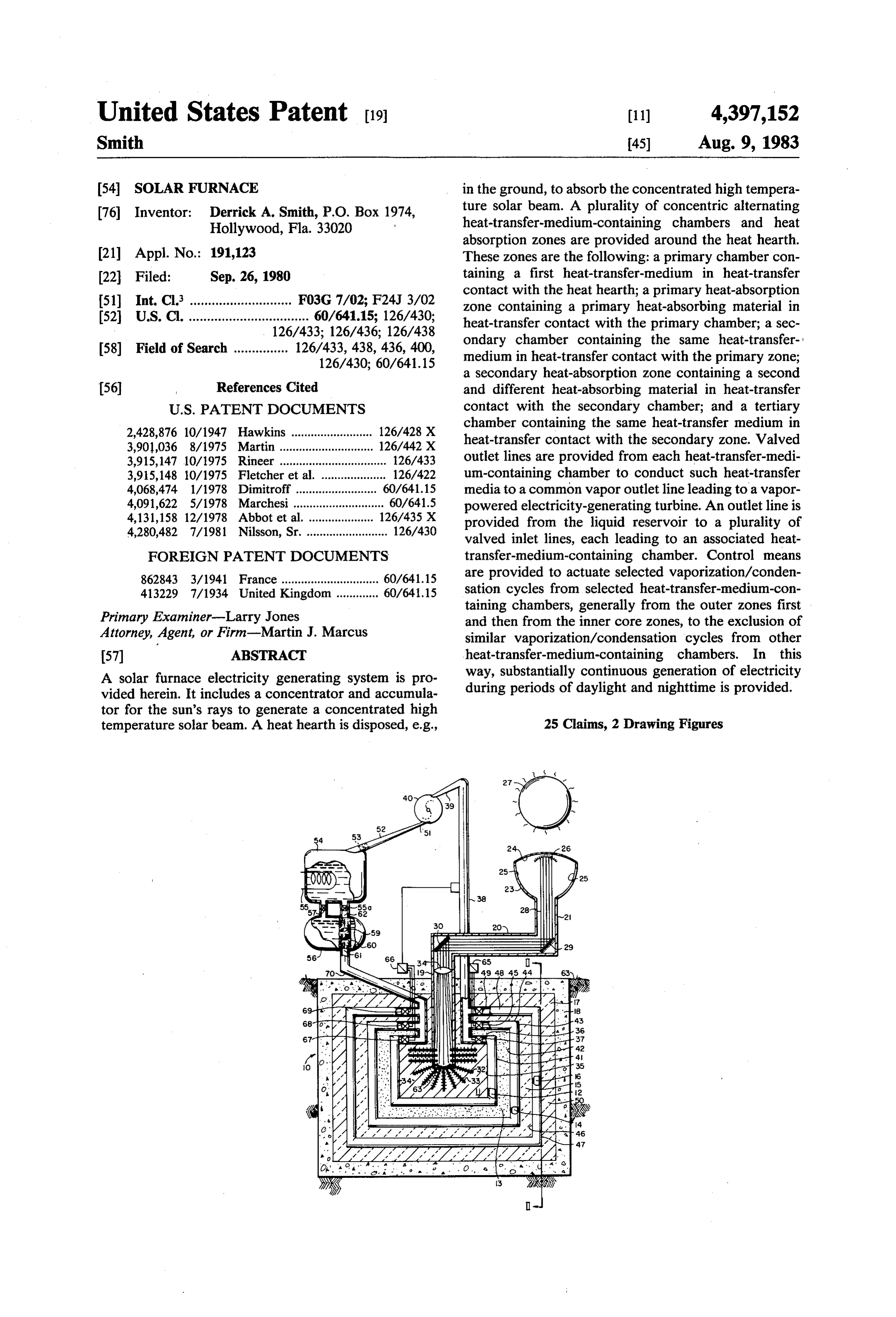
United States Patent (19) 11) 4,397,152 Smith 45) Aug. 9, 1983 54 SOLAR FURNACE in the ground, to absorb the concentrated high tempera 76) Inventor: Derrick A. Smith, P.O. Box 1974, ture solar beam. A plurality of concentric alternating Hollywood, Fla. 33020 heat-transfer-medium-containing chambers and heat absorption zones are provided around the heat hearth.
21 Appl. No.: 191,123 These zones are the following: a primary chamber con 22 Filed: Sep. 26, 1980 taining a first heat-transfer-medium in heat-transfer contact with the heat hearth; a primary heat-absorption 51) Int. Cl............................. F03G 7/02; F24J 3/02 zone containing a primary heat-absorbing material in 52 U.S. C. ................................. 60/641.15; 126/430; heat-transfer contact with the primary chamber; a sec 126/433; 126/436; 126/438 ondary chamber containing the same heat-transfer 58) Field of Search ............... 126/433,438, 436, 400, medium in heat-transfer contact with the primary zone; 126/430; 60/641.15 a secondary heat-absorption Zone containing a second (56) References Cited and different heat-absorbing material in heat-transfer
2,428,876 10/1947 Hawkins ......................... 126/428 X chamber containing the same heat-transfer medium in 3,901,036 8/1975 Martin...... 126/442 X heat-transfer contact with the secondary zone. Valved 3,915,147 10/1975 Rineer ................................. 26/433 outlet lines are provided from each heat-transfer-medi 3,915,148 10/1975 Fletcher et al. .................... 126/422 un-containing chamber to conduct such heat-transfer 4,068,474 1/1978 Dimitroff..... ... 60/641.15 media to a common vapor outlet line leading to a vapor 4,091,622 5/1978 Marchesi...... ... 60/641.5 powered electricity-generating turbine. An outlet line is 4,131,158 12/1978 Abbot et al. . . 126/435 X provided from the liquid reservoir to a plurality of 4,280,482 7/1981 Nilsson, Sr. ......................... 126/430 valved inlet lines, each leading to an associated heat FOREIGN PATENT DOCUMENTS transfer-medium-containing chamber. Control means 862843 3/1941 France .............................. 60/641.15 are provided to actuate selected vaporization/conden 413229 7/1934 United Kingdom ............. 60/64.15 sation cycles from selected heat-transfer-medium-con Primary Examiner-Larry Jones taining chambers, generally from the outer zones first and then from the inner core zones, to the exclusion of
Attorney, Agent, or Firm-Martin J. Marcus similar vaporization/condensation cycles from other 57 ABSTRACT heat-transfer-medium-containing chambers. In this A solar furnace electricity generating system is pro way, substantially continuous generation of electricity vided herein. It includes a concentrator and accumula during periods of daylight and nighttime is provided. tor for the sun's rays to generate a concentrated high temperature solar beam. A heat hearth is disposed, e.g., 25 Claims, 2 Drawing Figures
es 3. 20
SO 29
SS 6 68 3. 65 70as 9 49 48 45. 44 S3
...to' SaS 2. . c. a. a a & ," A
O. M a 4/14/.447
68a. a -36 st -1 37
o: w o 35 a - 8 o a 2 - a Å,
K i &. a T PS& e a 14
M a 46
M 1- at
a 4. ? M 1-44, M
C'. . . . .. . .. . os . . . . .
Page 2
Drawing sheet — no readable text.
Page 3
Drawing sheet — no readable text.
Page 4
By another feature thereof, each such heat-absorbing
SOLAR FURNACE metal rod projects into the heat hearth and is provided with a plurality of heat-dissipating ribs.
BACKGROUND OF THE INVENTION By another feature, the heat hearth is packed with a (i) Field of the Invention heat-absorbing, heat-transfer material. This invention relates to a solar furnace and means By another feature, the heat-absorbing, heat-transfer material is comminuted metal.
associated therewith for generating electric power from By other features thereof, the number of concentric the energy of the sun. heat-transfer zones and heat-absorption zones can be (ii) Description of the Prior Art 10 extended practically indefinitely to accommodate the Electricity is one of the most widely used forms of heat storage capacity required. energy. It is known that electricity may be produced by By another feature thereof, each such primary, sec hydroelectric generators, combustion engines powered ondary by expensive fuels, e.g., oil or natural gas, by electromo walled, and tertiary chamber comprises a double tive steam engines powered by coal, or oil, or by the use 15 formed ofhollow,
rectangular parallelepiped chamber heat-conducting, structural material such as of natural energy. These procedures suffer the defi steel.
ciency that they may use diminishing non-renewable By another feature, the primary zone is packed with resources, and of pollution of the atmosphere. More a heat-transfer medium such as sand, stone or clay. over, in many parts of the world, there is no access to By another feature, the seconeary zone is packed facilities for generating electricity by hydrogenerators. 20 with a heat-transfer medium such as bricks. SUMMARY OF THE INVENTION By another feature, the system includes a first heat (i) Aims of the Invention insulating zone in heat-transfer contact with the tertiary chamber.
It would therefore be advantageous to be able to By another feature thereof, the first heat-insulating produce electricity through the use of a readily avail- 25 zone is packed with a heat-insulating material such as able renewable energy source. It should also be applica asbestos.
ble wherever sunlight is available and where a finite By another feature, the system is encased in a heat supply of a heat-transfer fluid is available. insulating structural casing such as concrete. (ii) Statement of the Invention
By this invention, a solar furnace electricity generat- so (a)Byincludes another feature of this invention, the concentrator a semi-globular hollow one-way mirrored ing system is provided comprising: (a) a concentrator bulb terminating in a depending shaft for the passage of and accumulator for the sun's rays to generate a concen the collimated concentrated high temperature solar trated high temperature solar beam; (b) a heat hearth beam.
disposed to absorb heat from the concentrated high By another feature, the semi-globular bulb includes temperature solar beam; (c) a plurality of concentric 35 additional heat-reflecting internal mirrors to assist in alternating heat-transfer-medium-containing chambers collimating and concentrating the sun's rays. and heat absorption zones around the heat hearth, the By another feature, the system includes at least one plurality of zones comprising; (i) a primary chamber connecting heat-conducting shaft to convey the solar containing a first heat-transfer-medium in heat-transfer beam to the heat shaft, assisted by 45 reflectors. contact with the heat hearth; (ii) a primary heat-absorp- 40 By other features thereof, the angle of the reflectors tion Zone containing a primary heat-absorbing material can be varied from 45 to facilitate the angle of the tubes in heat-transfer contact with the primary chamber; (iii) which will be unique for each solar furnace of embodi a secondary chamber containing the same heat-transfer ments of this invention.
medium in heat-transfer contact with the primary zone; By another feature, the heat shaft includes a heat (iv) a secondary heat-absorption zone containing a sec- 45 concentrating lens therein.
ond and different heat-absorbing material in heat-trans By another feature, the valves in the outlets from fer contact with the secondary chamber; and (v) a ter each heat-transfer-medium-containing chamber are one tiary chamber containing the same heat-transfer-medi way valves adapted to open automatically at a minimum um-containing chamber to conduct such heat-transfer pre-set vapour pressure.
media to a common vapour outlet line leading to a 50 By another feature of this invention, the valves in the vapour-powered electricity-generating turbine; (e) outlets to each heat-transfer-medium-containing cham valved outlet line from the turbine to a liquid reservoir; ber are one-way valves adapted to open upon positive (f) valved outlet means from the liquid reservoir to a activation provided a minimum pre-set vapour pressure plurality of valved inlet lines, each leading to an associ condition is satisfied.
ated heat-transfer-medium-containing chamber; and (g) 55 By another feature, the valve on the outlet line from control means to actuate selected vapourization/con the turbine is a one-way valve adapted to be opened densation cycles from selected heat-transfer-medium upon positive activation.
containing chambers, to the exclusion of similar vapou By another feature, the reservoir includes an upper rization/condensation cycles from other heat-transfer primary reservoir and a lower liquid transfer reservoir. medium-containing chambers; thereby to result in sub- 60 By another feature thereof, the upper reservoir is stantially continuous generation of electricity during provided with auxiliary heat exchanger to recover sen periods of daylight and nighttime. sible heat from liquid in the upper reservoir. (iii) Other Features of the Invention By another feature, the primary reservoir is con By a feature thereof, the heat hearth is provided with nected to the lower liquid transfer reservoir by means of a central heat shaft to absorb heat from the concen- 65 a primary check-valved flow conduit, and by a second trated high temperature solar beam. ary, ball valve controlled flow conduit, the ball valve By another feature thereof, the heat shaft is pierced being a caged valve which moves in a controlled fash by a plurality of heat-absorbing metal rods. ion either to seal a main outlet from the lower liquid
Page 5
transfer reservoir, or to allow liquid to enter the lower Disposed concentrically around the main heat hearth liquid transfer reservoir from the primary reservoir. 11 between the main heat hearth 11 and the primary By a further variant, the system includes a parallel heat-absorption zone 13 is the primary chamber 12 con auxiliary flow system operated by a positively powered taining a heat-transfer medium. The primary chamber pump. 12 has a single outlet conduit 36 leading by way of a By another feature of this invention, the heat-transfer check valve 37 to an upwardly extending common va medium is water. pour shaft 38 which preferably is insulated (not shown). BRIEF DESCRIPTION OF THE DRAWINGS Vapour shaft 38 leads to the inlet 39 of a vapour-pow ered electricity-generating turbine 40. While water is
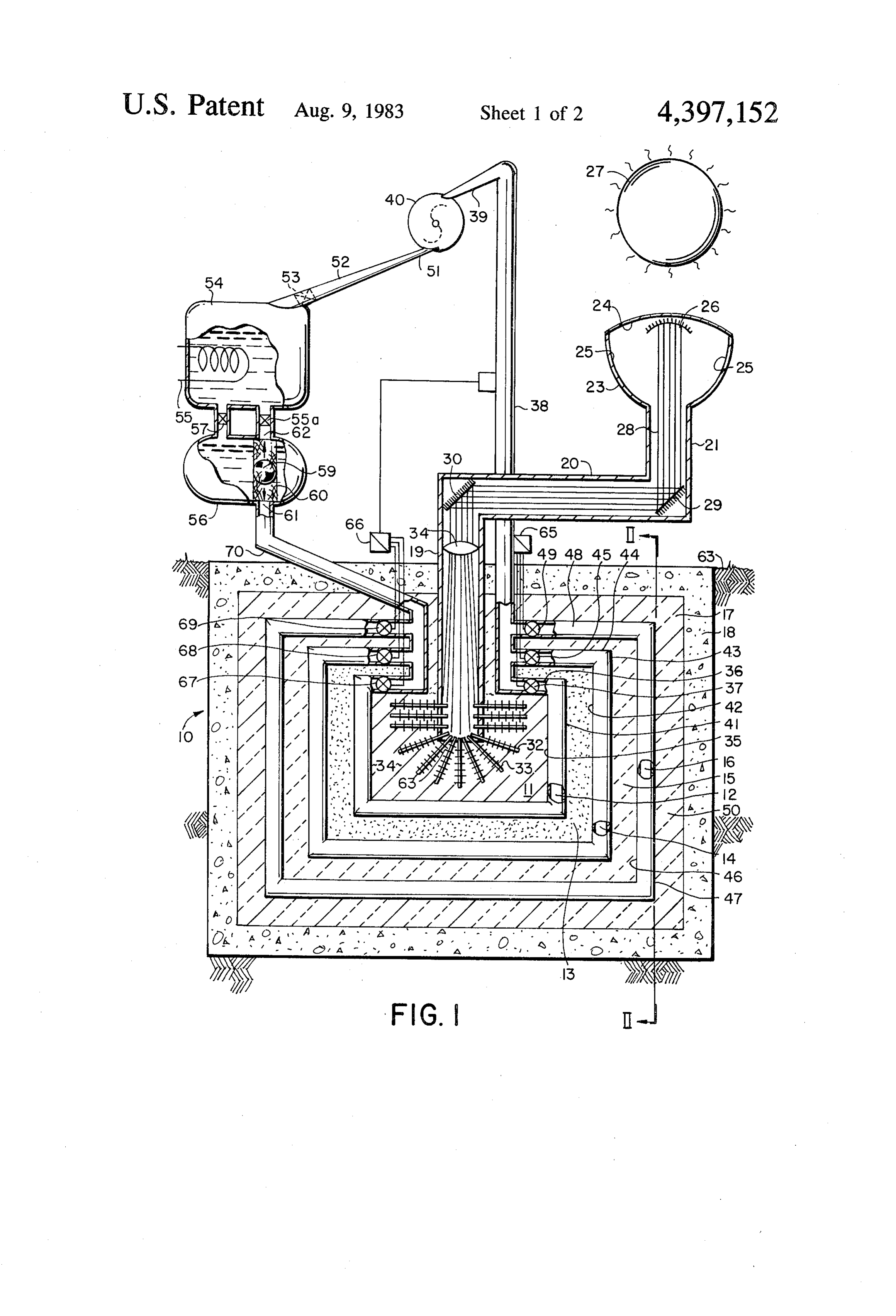
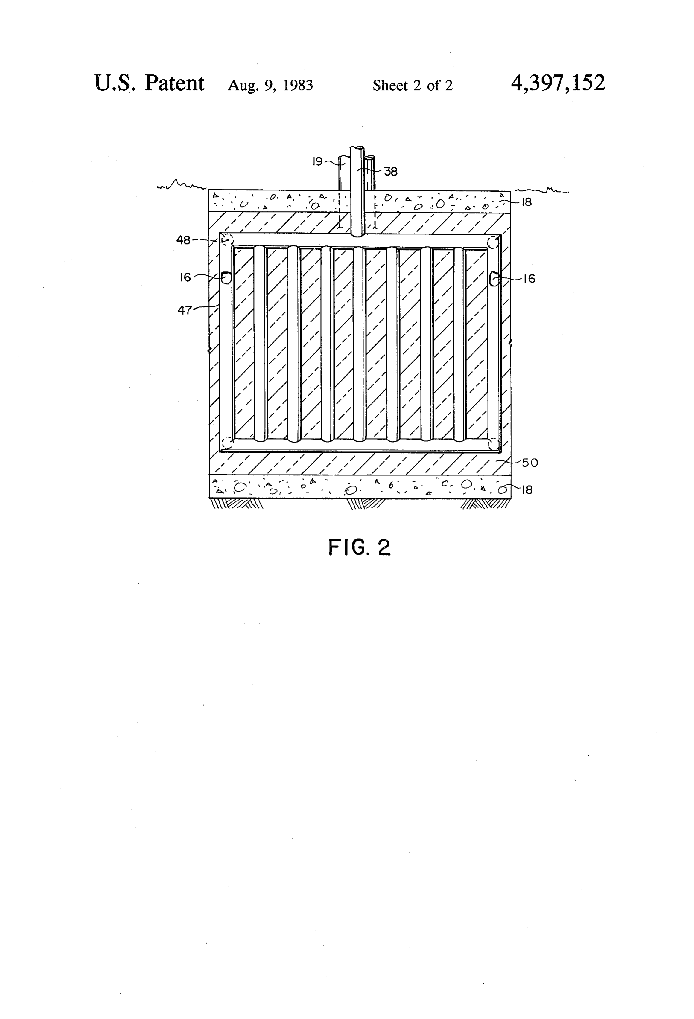
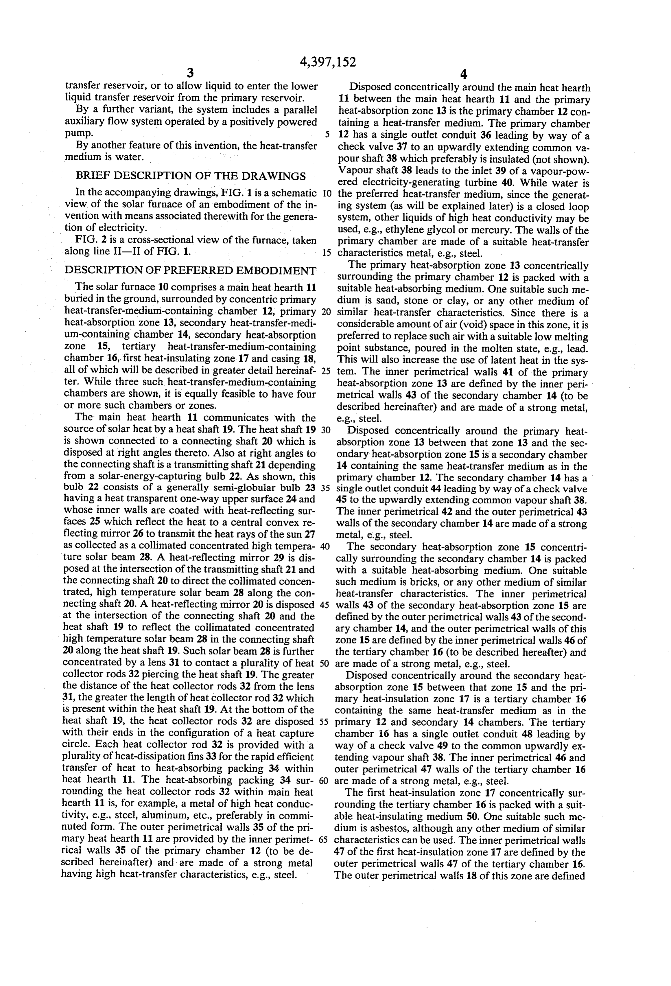
In the accompanying drawings, FIG. 1 is a schematic 10 the preferred heat-transfer medium, since the generat view of the solar furnace of an embodiment of the in ing system (as will be explained later) is a closed loop vention with means associated therewith for the genera system, other liquids of high heat conductivity may be tion of electricity. used, e.g., ethylene glycol or mercury. The walls of the FIG. 2 is a cross-sectional view of the furnace, taken primary chamber are made of a suitable heat-transfer along line II-II of FIG. 1. 15 characteristics metal, e.g., steel. DESCRIPTION OF PREFERRED EMBODIMENT The primary heat-absorption zone 13 concentrically surrounding the primary chamber 12 is packed with a
The solar furnace 10 comprises a main heat hearth 11 suitable heat-absorbing medium. One suitable such me buried in the ground, surrounded by concentric primary dium is sand, stone or clay, or any other medium of heat-transfer-medium-containing chamber 12, primary 20 similar heat-transfer characteristics. Since there is a heat-absorption zone 13, secondary heat-transfer-medi considerable amount of air (void) space in this zone, it is um-containing chamber 14, secondary heat-absorption preferred to replace such air with a suitable low melting zone 15, tertiary heat-transfer-medium-containing point substance, poured in the molten state, e.g., lead. chamber 16, first heat-insulating zone 17 and casing 18, This will also increase the use of latent heat in the sys all of which will be described in greater detail hereinaf 25 tem. The inner perimetrical walls 41 of the primary ter. While three such heat-transfer-medium-containing heat-absorption zone 13 are defined by the inner peri chambers are shown, it is equally feasible to have four metrical walls 43 of the secondary chamber 14 (to be or more such chambers or zones. described hereinafter) and are made of a strong metal, The main heat hearth 11 communicates with the e.g., steel.
source of solar heat by a heat shaft 19. The heat shaft 19 30 Disposed concentrically around the primary heat is shown connected to a connecting shaft 20 which is absorption zone 13 between that zone 13 and the sec disposed at right angles thereto. Also at right angles to ondary heat-absorption zone 15 is a secondary chamber the connecting shaft is a transmitting shaft 21 depending 14 containing the same heat-transfer medium as in the from a solar-energy-capturing bulb. 22. As shown, this primary chamber 12. The secondary chamber 14 has a bulb 22 consists of a generally semi-globular bulb 23 35 single outlet conduit 44 leading by way of a check valve having a heat transparent one-way upper surface 24 and 45 to the upwardly extending common vapour shaft 38. whose inner walls are coated with heat-reflecting sur The inner perimetrical 42 and the outer perimetrical 43 faces 25 which reflect the heat to a central convex re walls of the secondary chamber 14 are made of a strong flecting mirror 26 to transmit the heat rays of the sun 27 metal, e.g., steel.
as collected as a collimated concentrated high tempera 40 The secondary heat-absorption zone 15 concentri ture solar beam 28. A heat-reflecting mirror 29 is dis cally surrounding the secondary chamber 14 is packed posed at the intersection of the transmitting shaft 21 and with a suitable heat-absorbing medium. One suitable the connecting shaft 20 to direct the collimated concen such medium is bricks, or any other medium of similar trated, high temperature solar beam 28 along the con heat-transfer characteristics. The inner perimetrical necting shaft 20. A heat-reflecting mirror 20 is disposed 45 walls 43 of the secondary heat-absorption zone 15 are at the intersection of the connecting shaft 20 and the defined by the outer perimetrical walls 43 of the second heat shaft 19 to reflect the collimatated concentrated ary chamber 14, and the outer perimetrical walls of this high temperature solar beam 28 in the connecting shaft zone 15 are defined by the inner perimetrical walls 46 of 20 along the heat shaft 19. Such solar beam 28 is further the tertiary chamber 16 (to be described hereafter) and concentrated by a lens 31 to contact a plurality of heat 50 are made of a strong metal, e.g., steel. collector rods 32 piercing the heat shaft 19. The greater Disposed concentrically around the secondary heat the distance of the heat collector rods 32 from the lens absorption zone 15 between that zone 15 and the pri 31, the greater the length of heat collector rod 32 which mary heat-insulation zone 17 is a tertiary chamber 16 is present within the heat shaft 19. At the bottom of the containing the same heat-transfer medium as in the heat shaft 19, the heat collector rods 32 are disposed 55 primary 12 and secondary 14 chambers. The tertiary with their ends in the configuration of a heat capture chamber 16 has a single outlet conduit 48 leading by circle. Each heat collector rod 32 is provided with a way of a check valve 49 to the common upwardly ex plurality of heat-dissipation fins 33 for the rapid efficient tending vapour shaft 38. The inner perimetrical 46 and transfer of heat to heat-absorbing packing 34 within outer perimetrical 47 walls of the tertiary chamber 16 heat hearth 11. The heat-absorbing packing 34 sur 60 are made of a strong metal, e.g., steel. rounding the heat collector rods 32 within main heat The first heat-insulation zone 17 concentrically sur hearth 11 is, for example, a metal of high heat conduc rounding the tertiary chamber 16 is packed with a suit tivity, e.g., steel, aluminum, etc., preferably in commi able heat-insulating medium 50. One suitable such me nuted form. The outer perimetrical walls 35 of the pri dium is asbestos, although any other medium of similar mary heat hearth 11 are provided by the inner perimet 65 characteristics can be used. The inner perimetrical walls rical walls 35 of the primary chamber 12 (to be de 47 of the first heat-insulation zone 17 are defined by the scribed hereinafter) and are made of a strong metal outer perimetrical walls 47 of the tertiary chamber 16. having high heat-transfer characteristics, e.g., steel. The outer perimetrical walls 18 of this zone are defined
Page 6
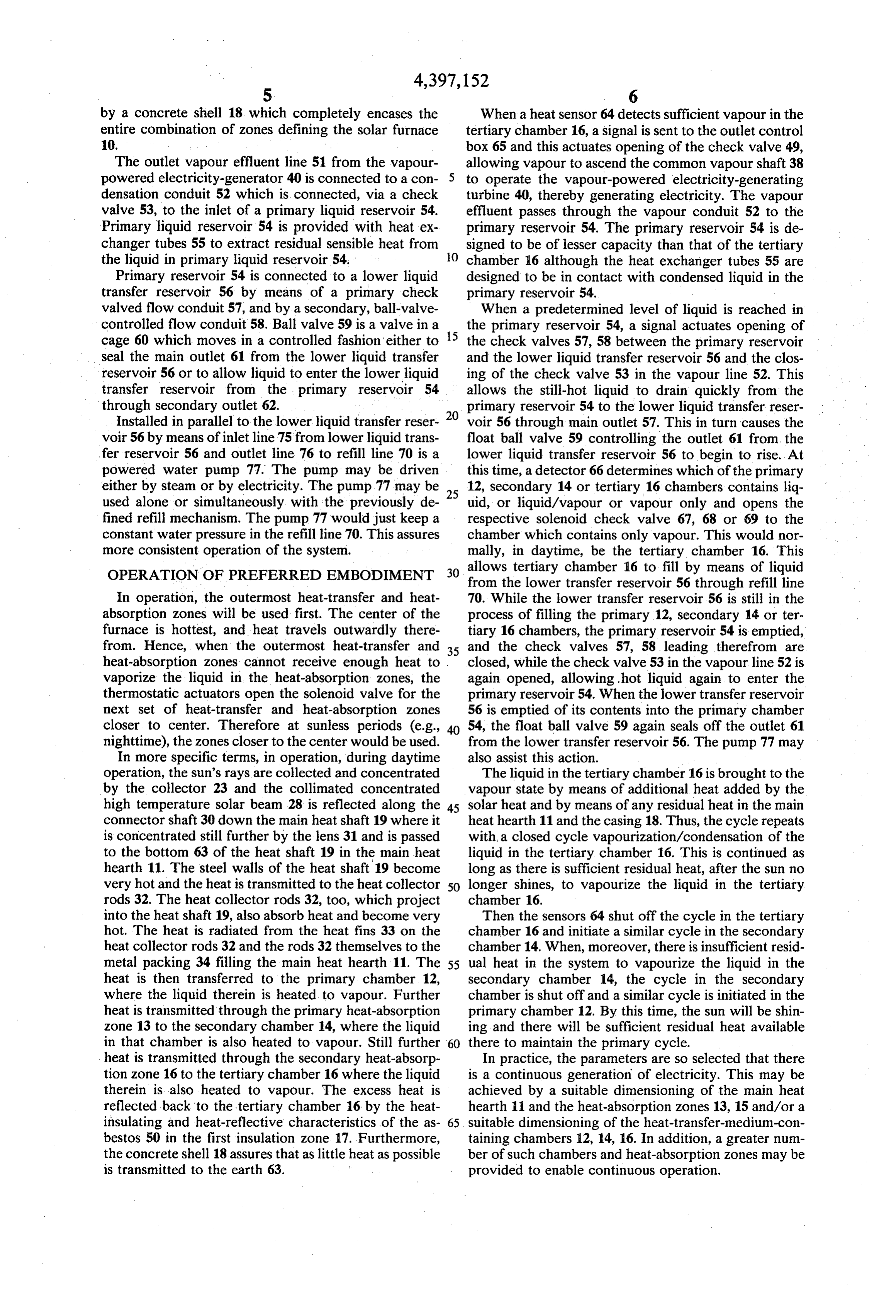
by a concrete shell 18 which completely encases the When a heat sensor 64 detects sufficient vapour in the entire combination of zones defining the solar furnace tertiary chamber 16, a signal is sent to the outlet control O. box 65 and this actuates opening of the check valve 49, The outlet vapour effluent line 51 from the vapour allowing vapour to ascend the common vapour shaft 38 powered electricity-generator 40 is connected to a con to operate the vapour-powered electricity-generating densation conduit 52 which is connected, via a check turbine 40, thereby generating electricity. The vapour valve 53, to the inlet of a primary liquid reservoir 54. effluent passes through the vapour conduit 52 to the Primary liquid reservoir 54 is provided with heat ex primary reservoir 54. The primary reservoir 54 is de changer tubes 55 to extract residual sensible heat from signed to be of lesser capacity than that of the tertiary the liquid in primary liquid reservoir 54. O chamber 16 although the heat exchanger tubes 55 are Primary reservoir 54 is connected to a lower liquid designed to be in contact with condensed liquid in the transfer reservoir 56 by means of a primary check primary reservoir 54.
valved flow conduit 57, and by a secondary, ball-valve When a predetermined level of liquid is reached in controlled flow conduit 58. Ball valve 59 is a valve in a
the primary reservoir 54, a signal actuates opening of cage 60 which moves in a controlled fashion either to the check valves 57, 58 between the primary reservoir seal the main outlet 61 from the lower liquid transfer and the lower liquid transfer reservoir 56 and the clos reservoir 56 or to allow liquid to enter the lower liquid ing of the check valve 53 in the vapour line 52. This transfer reservoir from the primary reservoir 54 allows the still-hot liquid to drain quickly from the through secondary outlet 62. primary reservoir 54 to the lower liquid transfer reser Installed in parallel to the lower liquid transfer reser 20 voir 56 through main outlet 57. This in turn causes the voir 56 by means of inlet line 75 from lower liquid trans float ball valve 59 controlling the outlet 61 from the fer reservoir 56 and outlet line 76 to refill line 70 is a lower liquid transfer reservoir 56 to begin to rise. At powered water pump 77. The pump may be driven this time, a detector 66 determines which of the primary either by steam or by electricity. The pump 77 may be 25 12, secondary 14 or tertiary 16 chambers contains liq used alone or simultaneously with the previously de uid, or liquid/vapour or vapour only and opens the fined refill mechanism. The pump 77 would just keep a respective solenoid check valve 67, 68 or 69 to the constant water pressure in the refill line 70. This assures chamber which contains only vapour. This would nor more consistent operation of the system. mally, in daytime, be the tertiary chamber 16. This OPERATION OF PREFERRED EMBODIMENT 30 allows tertiary chamber 16 to fill by means of liquid from the lower transfer reservoir 56 through refill line
In operation, the outermost heat-transfer and heat 70. While the lower transfer reservoir 56 is still in the absorption zones will be used first. The center of the process of filling the primary 12, secondary 14 or ter furnace is hottest, and heat travels outwardly there tiary 16 chambers, the primary reservoir 54 is emptied, from. Hence, when the outermost heat-transfer and 35 and the check valves 57, 58 leading therefrom are heat-absorption zones cannot receive enough heat to . closed, while the check valve 53 in the vapour line 52 is vaporize the liquid in the heat-absorption zones, the again opened, allowing, hot liquid again to enter the thermostatic actuators open the solenoid valve for the primary reservoir 54. When the lower transfer reservoir next set of heat-transfer and heat-absorption zones 56 is emptied of its contents into the primary chamber closer to center. Therefore at sunless periods (e.g., 54, the float ball valve 59 again seals off the outlet 61 nighttime), the zones closer to the center would be used. from the lower transfer reservoir 56. The pump 77 may In more specific terms, in operation, during daytime also assist this action.
operation, the sun's rays are collected and concentrated The liquid in the tertiary chamber 16 is brought to the by the collector 23 and the collimated concentrated vapour state by means of additional heat added by the high temperature solar beam 28 is reflected along the 45 solar heat and by means of any residual heat in the main connector shaft 30 down the main heat shaft 19 where it heat hearth 11 and the casing 18. Thus, the cycle repeats is concentrated still further by the lens 31 and is passed with, a closed cycle vapourization/condensation of the tohearth the bottom 63 of the heat shaft 19 in the main heat liquid in the tertiary chamber 16. This is continued as 11. The steel walls of the heat shaft 19 become long as there is sufficient residual heat, after the sun no very hot and the heat is transmitted to the heat collector 50 longer shines, to vapourize the liquid in the tertiary rods 32. The heat collector rods 32, too, which project chamber 16.
into the heat shaft 19, also absorb heat and become very Then the sensors 64 shut off the cycle in the tertiary hot. The heat is radiated from the heat fins 33 on the chamber 16 and initiate a similar cycle in the secondary heat collector rods 32 and the rods 32 themselves to the chamber 14. When, moreover, there is insufficient resid metal packing 34 filling the main heat hearth 11. The 55 ual heat in the system to vapourize the liquid in the heat is then transferred to the primary chamber 12, secondary chamber 14, the cycle in the secondary where the liquid therein is heated to vapour. Further chamber is shut off and a similar cycle is initiated in the heat is transmitted through the primary heat-absorption primary chamber 12. By this time, the sun will be shin zone 13 to the secondary chamber 14, where the liquid ing and there will be sufficient residual heat available in that chamber is also heated to vapour. Still further 60 there to maintain the primary cycle. heat is transmitted through the secondary heat-absorp In practice, the parameters are so selected that there tion zone 16 to the tertiary chamber 16 where the liquid is a continuous generation of electricity. This may be therein is also heated to vapour. The excess heat is achieved by a suitable dimensioning of the main heat reflected back to the tertiary chamber 16 by the heat hearth 11 and the heat-absorption zones 13, 15 and/or a insulating and heat-reflective characteristics of the as 65 suitable dimensioning of the heat-transfer-medium-con bestos 50 in the first insulation zone 17. Furthermore, taining chambers 12, 14, 16. In addition, a greater num the concrete shell 18 assures that as little heat as possible ber of such chambers and heat-absorption zones may be is transmitted to the earth 63. provided to enable continuous operation.
Page 7
SUMMARY 6. The system of claim 5 wherein said heat-absorbing, heat-transfer material is comminuted metal.
From the foregoing description, one skilled in the art 7. The system of claim 1 wherein each said primary, can easily ascertain the essential characteristics of this secondary and tertiary chambers comprises a double invention, and without departing from the spirit and 5 walled, hollow, rectangular parallelepiped chamber scope thereof, can make various changes and modifica formed of a heat-conducting, structural material. tions of the invention to adapt it to various usages and 8. The system of claim 1 wherein said primary heat conditions. Consequently, such changes and modifica absorbing material is selected from the group consisting tions are properly, equitably, and "intended' to be, of sand, stone and clay.
within the full range of equivalence of the following 10 9. The system of claim 8 including an auxiliary pack claims. ing of lead as a molten, low melting point substance. What I claim is: 10. The system of claim 1 wherein said secondary 1. A solar furnace electricity generating system com heat-absorbing material is bricks. prising: 11. The system of claim 1 including a first heat (a) a concentrator and accumulator for the sun's rays 15 insulating zone in heat-transfer contact with said ter to generate a concentrated high temperature solar tiary chamber.
beam; 12. The system of claim 11 wherein said first heat (b) a heat hearth disposed to absorb heat from said insulating Zone is packed with asbestos as a heat-insulat concentrated high temperature solar beam; ing material.
(c) a plurality of concentric alternating heat-transfer 20 13. The system of claim 1 encased in concrete as a medium-containing chambers and heat absorption zones around said heat hearth, said plurality of heat-insulating structural casing. 14. The system of claim 1 wherein said concentrator
Zones comprising (a) includes a semi-globular hollow one-way mirror (i) a primary chamber containing a first heat-trans bulb terminating in a depending shaft for the passage of fer-medium in heat-transfer contact with said 25 heat hearth; said collimated concentrated high temperature solar (ii) a primary heat-absorption zone containing a beam.
primary heat-absorbing material in heat-transfer 15. The system of claim 14 wherein said semi-globu contact with said primary chamber; lar bulb includes additional heat-reflecting internal mir (iii) a secondary chamber containing the same heat 30 rors to assist in collimating and concentrating said sun's rays.
transfer-medium in heat-transfer contact with said primary zone; 16. The system of claim 14 including at least one (iv) a secondary heat-absorption zone containing a connecting heat-conducting shaft to convey said solar second and different heat-absorbing material in beam to said heat shaft, assisted by 45 reflectors. heat-transfer contact with said secondary cham 35 17. The system of claim 14 wherein said heat shaft ber; and includes a heat concentrating lens therein. (v) a tertiary chamber containing the same heat 18. The system of claim 1 wherein said valves in the transfer-medium in heat-transfer contact with outlets from each said heat-transfer-medium-containing said secondary zone; chamber are one-way valves adapted to open automati (d) valved outlet lines leading from each said heating- 40 cally at a minimum pre-set vapour pressure. transfer-medium-containing chamber to conduct 19. The system of claim 1 wherein said valves in the such heat-transfer media to a common vapour out inlets to each said heat-transfer-medium-containing let line leading to a vapour-powered electricity chamber are one-way valves adapted to open upon generating turbine; positive activation provided a minimum pre-set vapour (e) valved outlet line from said turbine connected to a 45 pressure condition is satisfied. liquid reservoir; 20. The system of claim 1 wherein said valve on said (f) valved outlet means from said liquid reservoir to a outlet line from said turbine is a one-way valve adapted plurality of valved inlet lines, each leading to an to be opened upon positive activation. associated said heat-transfer-medium-containing 21. The system of claim 1 wherein said reservoir chamber; and 50 includes an upper primary reservoir and a lower liquid (g) control means to actuate selected vapourization/- transfer reservoir.
condensation cycles from selected heat-transfer 22. The system of claim 1 wherein said heat-transfer medium-containing chambers, to the exclusion of medium is water.
similar vapourization/condensation cycles from 23. The system of claim 1 wherein each of the pri other heat-transfer-medium-containing chambers; 55 mary, secondary and tertiary heat-transfer medium thereby to result in substantially continuous gener containing chambers comprise a plurality of intercon ation of electricity during periods of daylight nected, spaced apart, network of tubular members. and nighttime. 24. A solar furnace electricity generating system 2. The system of claim 1 wherein said heat hearth is comprising:
provided with a central heat shaft to absorb heat from 60 (a) a concentrator and accumulator for the sun's rays said concentrated high temperature solar beam. to generate a concentrated high temperature solar 3. The system of claim 2 wherein said heat shaft is beam;
pierced by a plurality of heat-absorbing metal rods. (b) a heat hearth disposed to absorb heat from said 4. The system of claim 3 wherein each said heat concentrated high temperature solar beam; absorbing metal rod projects into said heat hearth and is 65 (c) a plurality of concentric alternating heat-transfer provided with a plurality of heat-dissipating ribs. medium-containing chambers and heat absorption 5. The system of claim 4 wherein said heat hearth is zones around said heat hearth, said plurality of packed with a heat-absorbing, heat-transfer material. zones comprising
Page 8
(i) a primary chamber containing a first heat-trans zones around said heat hearth, said plurality of fer-medium in heat-transfer contact with said Zones comprising heat hearth; (i) a primary chamber containing a first heat-trans (ii) a primary heat-absorption zone containing a fer-medium in heat-transfer contact with said primary heat-absorbing material in heat-transfer 5 heat hearth;
contact with said primary chamber; (ii) a primary heat-absorption zone containing a (iii) a secondary chamber containing the same heat primary heat-absorbing material in heat-transfer transfer-medium in heat-transfer contact with contact with said primary chamber; said primary zone; (iii) a secondary chamber containing the same heat (iv) a secondary heat-absorption zone containing a 10 transfer-medium in heat-transfer contact with second and different heat-absorbing material in said primary zone;
heat-transfer contact with said secondary cham (iv) a secondary heat-absorption zone containing a ber; and second and different heat-absorbing material in (v) a tertiary chamber containing the same heat heat-transfer contact with said secondary cham transfer-medium in heat-transfer contact with 15 ber; and said secondary zone; (v) a tertiary chamber containing the same heat (d) valved outlet lines leading from each said heat transfer-medium in heat-transfer contact with transfer-medium-containing chamber to conduct said secondary zone;
such heat-transfer media to a common vapour out (d) valved outlet lines leading from each said heat let line leading to a vapour-powered electricity- 20 transfer-medium-containing chamber to conduct generating turbine; such heat-transfer media to a common vapour out (e) valved outlet line from said turbine connected to a let line leading to a vapour-powered electricity liquid reservoir, said reservoir including an upper generating turbine;
primary reservoir and a lower liquid transfer reser (e) valved outlet line from said turbine connected to a voir; 25 liquid reservoir, said reservoir including an upper (f) valved outlet means from said liquid reservoir to a primary reservoir and a lower liquid transfer reser plurality of valved inlet lines, each leading to an voir;
associated said heat-transfer-medium-containing (f) valved outlet means from said liquid reservoir to a chamber; plurality of valved inlet lines, each leading to an (g) control means to actuate selected vapourization/- 30 associated said heat-transfer-medium-containing condensation cycles from selected heat-transfer chamber;
medium-containing chambers, to the exclusion of (g) control means to actuate selected vapourization/- similar vapourization/condensation cycles from condensation cycles from selected heat-transfer other heat-transfer-medium-containing chambers; medium-containing chambers, to the exclusion of and 35 similar vapourization/condensation cycles from (h) said upper reservoir being provided with auxiliary other heat-transfer-medium-containing chambers; heat exchanger to recover sensible heat from liquid and in said upper reservoir; (h) said primary reservoir being connected to said thereby to result in substantially continuous gener lower liquid transfer reservoir by means of a pri ation of electricity during periods of daylight 40 mary check-valved flow conduit, and by a second and nighttime. ary, ball valve controlled flow conduit, said ball 25. A solar furnace electricity generating system valve being a caged valve which moves in a con comprising: trolled fashion either to seal a main outlet from said (a) a concentrator and accumulator for the sun's rays lower liquid transfer reservoir, or to allow liquid to to generate a concentrated high temperature solar 45 enter said lower liquid transfer reservoir from said beam; primary reservoir;
(b) a heat hearth disposed to absorb heat from said thereby to result in substantially continuous gener concentrated high temperature solar beam; ation of electricity during periods of daylight (c) a plurality of concentric alternating heat-transfer and nighttime.k sk ck sk k medium-containing chambers and heat absorption 50
Provenance
- Collection
- Cited prior art
- Original PDF
- patentimages.storage.googleapis.com →
- Filed
- 1980-09-26
- Pages
- 8
- Method
- pdftotext (the PDF's own text layer) + pdftoppm 300dpi page scans
- Source
- Google Patents bibliographic record
- Granted
- 1983-08-09
- Inventors
- Derrick A. Smith
- Transcribed from
- patentimages.storage.googleapis.com →