patent · US4194496
Solar heat storage systems
25 March 1980
Page 1 — bibliographic record
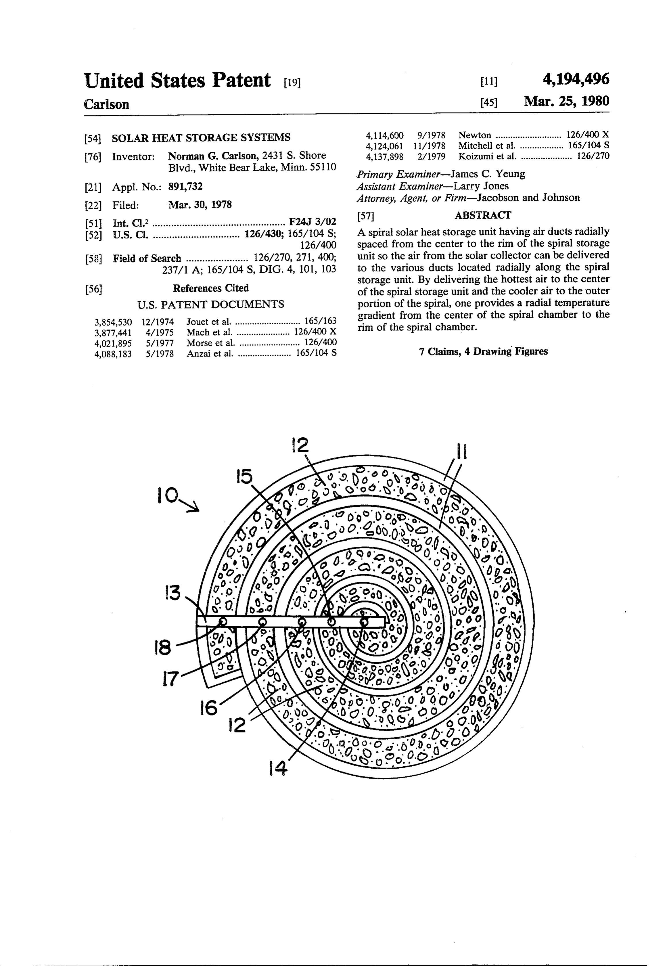
United States Patent (19) 11) 4,194,496 Carlson 45 Mar. 25, 1980 54 SOLAR HEAT STORAGESYSTEMS 4,114,600 9/1978 Newton ........................... 126/400 X 4,124,061 11/1978Mitchell et al. .. ... 165/104 S 76 Inventor: Norman G. Carlson, 2431 S. Shore 4,137,898 2/1979 Koizumi et al. ..................... 26/270 Blvd., White Bear Lake, Minn. 551 10 Primary Examiner-James C. Yeung (21) Appl. No.: 891,732 Assistant Examiner-Larry Jones 22 Filed: Mar. 30, 1978 Attorney, Agent, or Firm-Jacobson and Johnson (51] Int. Cl2. F24J 3/02 ABSTRACT 52) U.S. C. ................................ 126/430; 165/104 S; A spiral solar heat storage unit having air ducts radially 126/400 spaced from the center to the rim of the spiral storage 58) Field of Search ....................... 126/270, 271, 400; unit so the air from the solar collector can be delivered 237/1 A; 165/104 S, DIG. 4, 101, 103 to the various ducts located radially along the spiral Ref Ci storage unit. By delivering the hottest air to the center 56) eferences Cited of the spiral storage unit and the cooler air to the outer
3,854,530 12/1974 Jouet et al. ........................... 165/16 gradient from the center of the spiral chamber to the 3.377,441 4/i975 Machet al... 1600x rim of the spiral chamber.
4,021,895 5/1977 Morse et al. .. ... 126/400 4,088,183 5/1978 Anzai et al. ...................... 165/104 S 7 Claims, 4 Drawing Figures
Page 2
Drawing sheet — no readable text.
Page 3
13 having a first air duct 14, a second air duct 15, a third
SOLAR HEAT STORAGE SYSTEMS air duct 16, a fourth air duct 17 and a fifth air duct 18. Each of these ducts provide ingress or egress of air from
BACKGROUND OF THE INVENTION spiral storage unit 10. To illustrate the single spiral 1. Field of the Invention chamber, the top cover of chamber 10 was left out of This invention relates generally to solar systems and, F.G. In
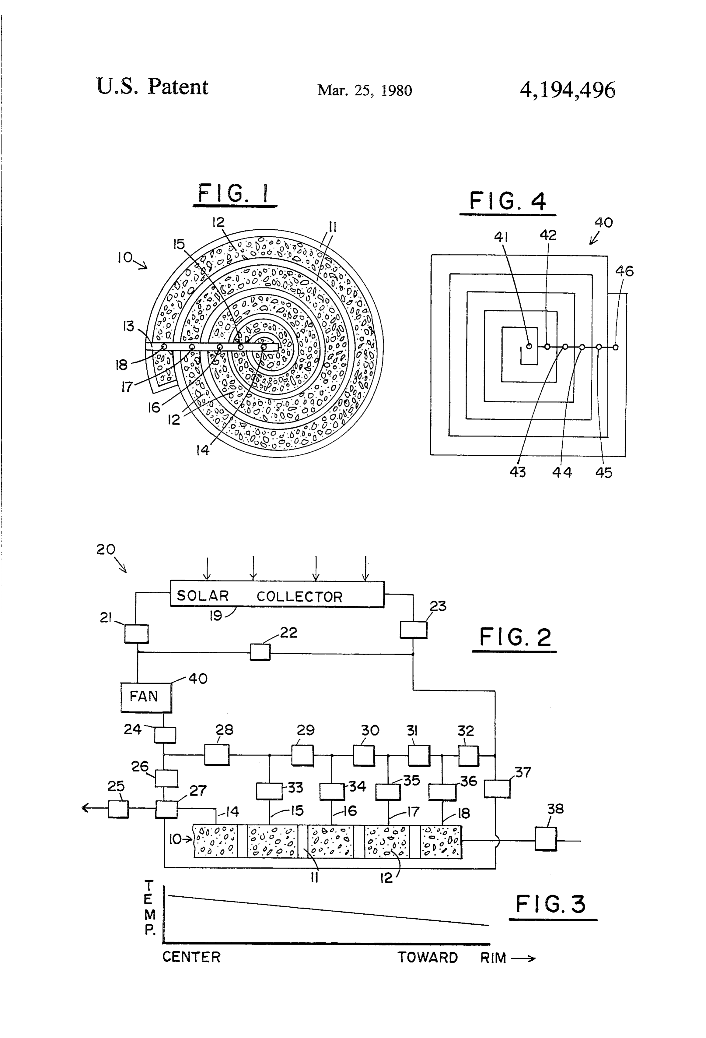
order to understand the operation of spiral storage more specifically, to solar storage units which can main tain a temperature gradient from the center to the rim of unit 10, reference should be made to FIG. 2 which the storage unit. shows a system 20 in schematic view comprising a solar 10 collector 19 connected to spiral storage unit 10. Refer 2. Description of the Prior Art
The concept of solar heat systems is old in the art as ence numerals 21 through 38 denote conventional tem evidenced by the Shoemaker U.S. Pat. No. 3,102,532 perature controlled air valves that open or close in which shows a solar heat unit disposed in the space of a response to a predetermined temperature setting. The chamber and comprising a mass of material having 15 operation of valves 21 through 38 will be described openings therein. The openings are readily permeable to with respect to the operation of system 20. For clarity the passage of air. The material may be a suitable porous only half of spiral storage unit 10 is shown in FIG. 2. pack of metal wool having surfaces to absorb radiant The lines shown connecting valves are air ducts for energy. directing air therethrough. The Jouet U.S. Pat. No. 3,854,530 shows a heat ex 20 Before proceeding with a description of the operation changer generally of cylindrical shape which provides of spiral storage unit 10, reference should be made to for the circulation of two fluids, each fluid following FIG. 3 which shows a temperature gradient graph from four identical spirals. the center of storage unit 10 to the rim of storage unit The Meckler U.S. Pat. No. 3,996,759 shows a strati 10. Note, the higher temperature rocks are at the center fied thermal mass which stores heated water from solar collectors according to its temperature. 25 of the spiral storage unit and the lower temperature rocks are at the rim of the spiral storage unit. This gradi
The Gay U.S. Pat. No. 2,584,573 shows method and ent is beneficial because heat loss to the surroundings is means for heating a house wherein heat is stored be minimized and heat sources of different temperatures neath the basement floor and fill of clay or heat conduc tive earth. The fill contains a labyrinth of pipes through are available. Also, since the laws of thermodynamics state that heat does not flow uphill, by having a storage which is circulated a heat transfer liquid. 30
The present invention differs from the prior art by unit with the a portion of the rocks at a high temperature providing a system for storing solar energy through a prompts conditions extended use of the storage unit under when the average temperature of the stored spiral chamber having multiple air inlets and outlets. heat may be less than room temperature. To achieve a BRIEF DESCRIPTION OF THE INVENTION 35 radially decreasing temperature, the air supply from
Briefly, the present invention comprises a radial heat in collector 19 is directed through air ducts 14 through 18 storage system having a spiral shape with a plurality of accordance with the temperature of the air. The radially spaced air ducts. Temperature control valves advantage of a spiral storage unit having a radially are mounted to the air ducts so that the hot air coming thermal gradient as shown in FIG. 3 will be more from the solar collector goes to the portion of the spiral 40 clearly understood during description of the operation storage unit which has a temperature less than the in of the systemtoshown in FIG. 2. coming air. Heated air can be removed from any por 20Referring FIG. 2, the operation of the solar system will be described under various conditions. Under tion of the spiral storage unit or through the entire spiral storage unit. the first condition, it will be assumed that the heat avail 45 able from collector 19 is sufficient to heat the building
BRIEF DESCRIPTION OF THE DRAWING with an excess for storage, i.e., T (temperature of air FIG. is a top view of my spiral solar collector; discharging from collector) is greater than T (tempera FIG. 2 is a schematic view of a solar system using my ture of the room). In this condition fan 40 sucks air from spiral storage unit; solar connector through valve 21. A temperature con FIG. 3 is a graph of spiral storage chamber tempera 50 trolled valve 24 allows air through valve 24, valve 26, ture as a function of radial position; and valve 27 and valve 25. Valve 27 is a three-way valve FIG. 4 is a schematic of an alternate embodiment of operable for simultaneously directing air into valve 25 my spiral storage unit. and valve 27. A thermostat (not shown) controls valve 27 to allow any excess hot air to flow into duct opening
DESCRIPTION OF THE PREFERRED 55 14 where the heat is dissipated in rocks 12. The hot air EMBODIMENT from valve 25 heats the building while the hot air flow Referring to the drawings, FIG. 1 shows a top view ing through valve 27 and into duct 14 loses heat to the of my spiral solar heat storage unit which is designated rocks as the air flows through spiral unit 10 and dis by reference numeral 10. Spiral solar storage unit 10 charges through valve 38. Valve 38 may be connected contains a concrete floor (not shown) and a vertical to solar collector 19 or vented to the outside. As air spiraling concrete wall 11. The spiral wall 11 produces flows through duct 14, each of valves 33-36 remain a continuous air path from the center of the spiral to the closed to allow air to flow along spiral storage unit 10. outside of the spiral. Rocks 12 or other suitable heat The hot air directed through valve 27 and into air duct storage means are located between adjacent spiral walls 14 spirals through the spiral solar storage unit until it to provide a porous air path and heat storage. Typically, 65 emerges at a lower temperature at valve 38. As the air spiral walls 11 can be made from concrete or they can flows through spiral 10 the rocks adjacent duct 14 re also be made from other materials such as metal. Lo ceive heat from the hot air with the rocks at the rim cated across the top of spiral storage unit 10 is a housing receiving heat from the cooler air.
Page 4
In a second condition, it will be assumed that solar The building can be cooled during the day by closing heat is available from connector 19, i.e., solar collector off valves 21 and 23 and opening valve 22 thus bypass air temperature T is greater than T, but the amount of ing the solar collector. The fan is used to inject room air heat in the solar collector air is insufficient to heat the into the rock where the rock temperature is equal or less building. In this condition fan 40 forces heated air from 5 than room temperature, for example, through valve 35. solar collector 19 through the valve 24. However, be This air flows to the right being cooled by the rocks. cause the air temperature is not sufficiently high, valve The cooled air exits through valves 25 and 27. 26 closes and valves 28 and 29 open. (It will be assumed It should be understood that the exact design of the that the temperature of the air from the solar collector spiral wall depends upon various factors such as the T is slightly greater than the temperature of rocks in 10 general climate where the building is located, the num spiral storage unit 10 at air duct 16.) Valve 30 remains ber of floors in the building, insulation in the building closed but valve 34 is open to allow air flow into solar andAccording pressure drop permissible in the spirals.
to design requirements, the number of storage unit 10 through duct 16. The air from solar connector 19 receives heat from rocks 12 as it spirals to spirals may vary from one to 20 or more. The design the center of unit 10 and flows out duct 14 through 15 requirements will influence the depth of the spirals and valve 27 and valve 25 to heat the room. By forcing air ter the ratio of width to depth and may vary from the cen through only a portion of solar storage unit 10, the heat varytoover the outside of the spiral. Typically, this ratio may a range of 5 to 0.1.
transfer to the air is minimized.
If the air from solar connector 19 T were not at 20 ingThe spiral storage unit may occupy an area compris a very small proportion of the floor area of the sufficient temperature to add heat to the storage unit, building (very low heat or cooling load) or it may oc the flow of air through collector 19 would be shunted cupy an area equal to or even larger than the floor area through valve 22. In this case, only the stored heat from of the building. In general, the total area of the spiral the stones and rocks would be available for heating the storage unit usually does not exceed the floor area of the building. However, if the air from solar connector 19 is 25 building.
above the temperature of any portion of the spiral con I claim:
nector, heat can be added to the spiral storage unit 1. The method of storing solar heat including: through the valves. forming a solar storage unit having a spiral passage Referring to FIG. 4, an alternate embodiment of the containing heat storage means located in the spiral spiral solar connector is shown having a rectangular 30 passage;
shape with the walls of the spiral narrowed at each forming air ducts at radially spaced distances along intermediate valve point by stub walls at right angles to said spiral passage and supplying heated air the spiral wall. Between the stub walls are inserted through at least one of said air ducts to said heat valves 41-46 having a perforated pipe with a steel panel storage means removing the air through another of extending between the stub walls. This panel is fitted as said air ducts in said spiral passage. with opening closed by tilting or sliding vanes. With the 2. A solar storage unit comprising: vanes closed, the spiral is cut off and with the vanes a top member, and a bottom member having a central open the spiral is open. The duct work may be located portion and an outer portion; on top of the spiral storage unit or recessed into the a wall connecting said top member to said bottom storage unit to provide a storage unit of continuous 40 member, said wall having one end located in the height to provide flexibility so only a portion of the central portion between said top member and said spiral storage unit may be used. bottom member, said wall spiraling outward to The above are only typical of the multiple uses of my thereby produce a spiral passage from said central spiral solar storage unit. In addition, by reversing the portion to said outer portion, heat storage means normal air flow at night the system can be used as a 45 located in said spiral passage; storage for "coolness.' In reverse flow, the air moves a set of air ducts radially spaced from the central from left to right through the collector being cooled by portion of said solar storage unit to said outer por conduction to the cool night air and/or by radiation tion of said storage unit to thereby provide air into space. This reverse flow air enters the heat storage passages to said spiral chamber intermediate the unit 10 at a point where the rocks are nearest the air 50 central portion and the outer portion of said solar temperature, for example, through valve 35. Part of the storage unit.
air discharges from the storage unit 10 at a point where 3. The invention of claim 2 wherein said solar storage the rocks are near room temperature, for example unit is connected for air flow with a solar collector. through valve 33, and returns to the left end of solar 4. The invention of claim 3 including temperature collector 19. The air discharging from solar storage unit 55 controlled valves for directing air from the solar con 10 has been warmed to room temperature by the rocks nector through said solar storage unit.
but the rocks have thereby been cooled by giving up 5. The invention of claim 4 wherein said spiral walls heat to the air thus storing "coolness'. A sufficient are acuate.
volume of air is allowed to flow to the left from valve 35 6. The invention of claim 4 wherein said spiral walls through the warn rocks exiting through valves 27 and 60 are comprised of straight sections.
25 to warm the building. Thus, the building is kept 7. The invention of claim 5 wherein said solar storage warm at night and "coolness' is stored for use during unit includes rocks for k storing
the day.
Page 5
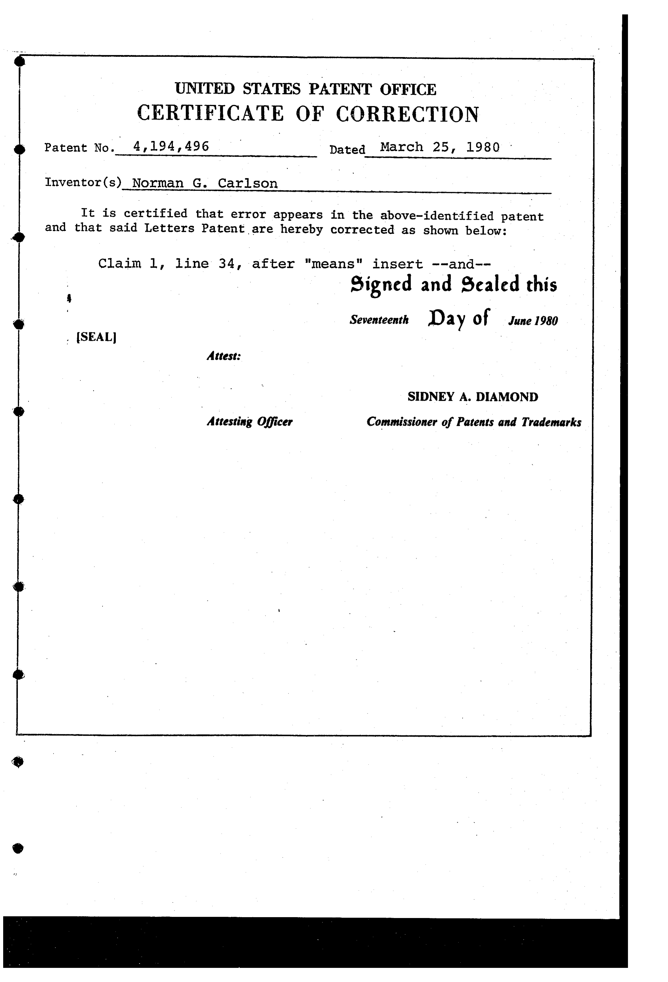
UNITED STATES PATENT OFFICE
CERTIFICATE OF CORRECTION
Inventor(s) Norman G. Carlson
It is certified that error appears in the above-identified patent and that said Letters Patent are hereby corrected as shown below: Claim 1, line 34, after "means" insert --and eigned and Sealed this
Seventeenth D 2 y O f June 1980
(SEAL
Attest:
SIDNEY A. DIAMOND
Attesting Officer Commissioner of Patents and Trademarks
Provenance
- Collection
- Cited prior art
- Original PDF
- patentimages.storage.googleapis.com →
- Filed
- 1978-03-30
- Pages
- 5
- Method
- pdftotext (the PDF's own text layer) + pdftoppm 300dpi page scans
- Source
- Google Patents bibliographic record
- Granted
- 1980-03-25
- Inventors
- Norman G. Carlson
- Transcribed from
- patentimages.storage.googleapis.com →