patent · US4524756
Thermal energy storage tank using modular heat batteries
25 June 1985
Page 1 — bibliographic record
United States Patent (19) 11 Patent Number: 4,524,756 Laverman 45 Date of Patent: Jun. 25, 1985 54 THERMAL ENERGY STORAGE TANK OTHER PUBLICATIONS
USING MODULAR HEAT BATTERIES
A paper by J. M. Friefeld et al, entitled "Design and 75) Inventor: Royce J. Laverman, South Holland, Construction of the "Solar One Thermal Storage Sub I. system' pp. 1468-1473, published by IEEE in 1982. 73) Assignee: Chicago Bridge & Iron Company, Oak Primary Examiner-William E. Lyddane Brook, Ill. Assistant Examiner-Gerald Anderson
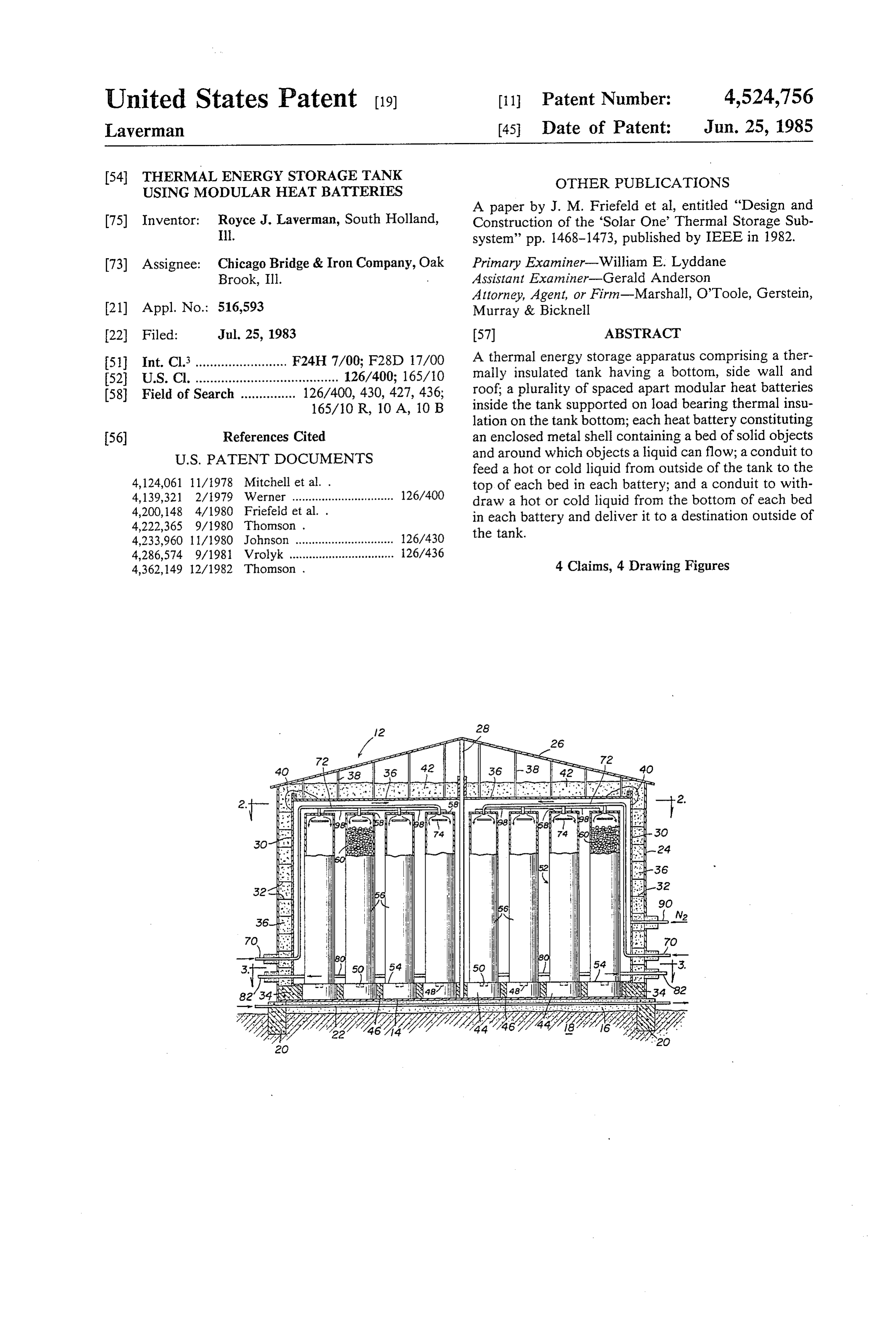
Attorney, Agent, or Firm-Marshall, O'Toole, Gerstein, 21) Appl. No.: 516,593 Murray & Bicknell 22 Filed: Jul. 25, 1983 57 ABSTRACT 51) Int. Cl.......................... F24H 7/00; F28D 17/00 A thermal energy storage apparatus comprising a ther 52 U.S. Cl. ....................................... 126/400; 165/10 mally insulated tank having a bottom, side wall and 58 Field of Search ............... 126/400, 430, 427, 436; roof; a plurality of spaced apart modular heat batteries 165/10 R, 10 A, 10 B inside the tank supported on load bearing thermal insu lation on the tank bottom; each heat battery constituting 56) References Cited an enclosed metal shell containing a bed of solid objects
feed a hot or cold liquid from outside of the tank to the 4,124,061 11/1978 Mitchell et al. . top of each bed in each battery; and a conduit to with 4,139,321 2/1979 Werner ............................... 126/400 draw a hot or cold liquid from the bottom of each bed 4,200,148 4/1980 Friefeld et al. . in each battery and deliver it to a destination outside of 4,222,365 9/1980 Thomson . the tank.
4,233,960 1 1/1980 Johnson .............................. 126/430 4,286,574 9/1981 Vrolyk ................................ 126/436 4,362,149 12/1982 Thomson . 4 Claims, 4 Drawing Figures
Page 2
Drawing sheet — no readable text.
Page 3
Drawing sheet — no readable text.
Page 4
ture change. Each battery is preferably supported on
THERMAL ENERGY STORAGE TANK USING load bearing thermal insulation. MODULAR HEAT BATTERIES According to a second aspect of the invention there is provided a method of storing thermal energy compris
This invention relates to the storage and extraction of ing distributing a flowing hot liquid to the top of a thermal energy. More particularly, this invention is plurality of heat storage batteries containing a bed of concerned with a thermal energy storage apparatus cold solid objects; allowing the hot liquid to flow down which employs a plurality of heat batteries of modular wardly in a trickle flow manner over the bed of solid design located in an insulated tank. objects contained in the heat storage batteries; allowing 10 a vertical temperature gradient, including a down
BACKGROUND OF THE INVENTION wardly moving thermocline heat transfer zone, with the With the recent interest in energy conservation and flowing hot liquid above the zone and the flowing cold efficiency, and with the development of solar energy liquid below the zone, to develop; and removing the technology, there has been considerable interest in the 15 cold liquid from below the thermocline heat transfer application of thermal energy storage. Many applica zone from the bottom of the heat storage batteries. tions, both industrial and commercial, have been evalu According to a third aspect of the invention there is ated for possible use of thermal energy storage con provided a method of recovering stored thermal energy cepts. The temperature range over which it is desired to comprising distributing a flowing cold liquid to the top store thermal energy varies considerably with these 20 of a plurality of heat storage batteries containing a bed different concepts, and range from approximately 200 of hot solid objects; allowing the cold liquid to flow F. to temperatures in excess of 1000 F. downwardly in a trickle flow manner over the bed of Many of the energy storage systems already proposed solid objects contained in the heat storage batteries; employ a tape of tank to contain the heated material. allowing a vertical temperature gradient, including a However, major design problem are involved with such 25 downwardly moving thermocline heat transfer zone in tanks because of the thermal movements associated which the cold liquid is located above the zone and hot with placing the storage tank in service and with the liquid is located below the zone, to develop in the heat normal temperature cycles through which it operates. storage batteries; and removing the hot liquid from These temperature variations cause considerable diffi below the thermocline heat transfer zone from the bot culty in the load bearing insulation and foundation of 30 tom of the heat storage batteries. the storage tank. A need accordingly exists for im BRIEF DESCRIPTION OF THE DRAWINGS proved thermal energy storage apparatus.
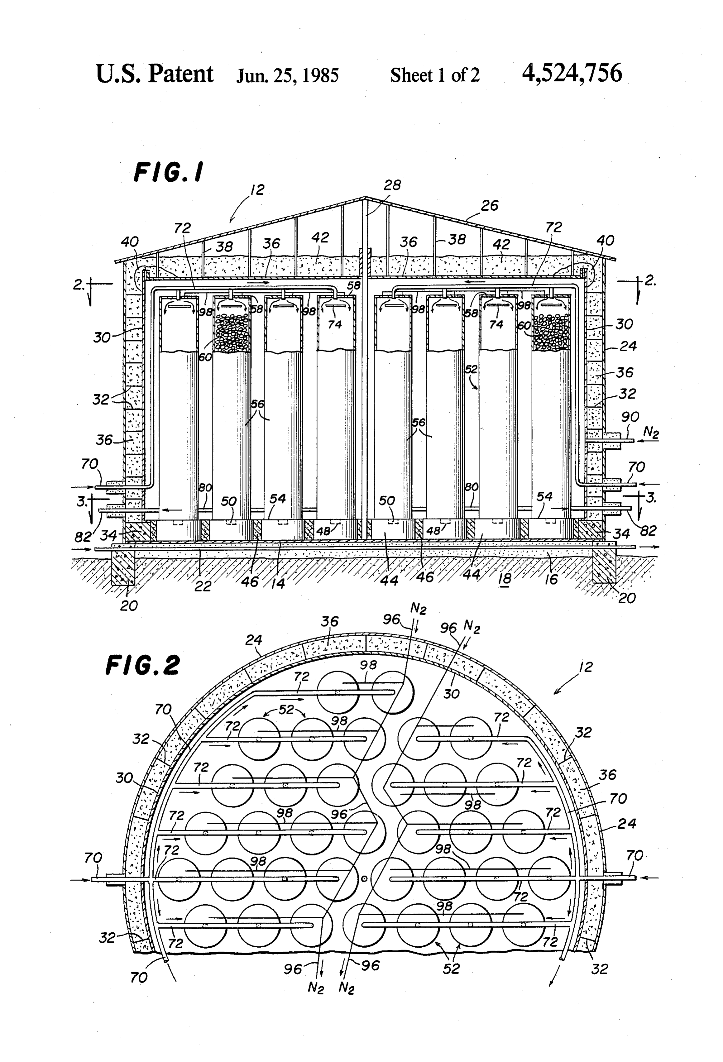
FIG. 1 illustrates a thermal energy storage apparatus,
SUMMARY OF THE INVENTION according to the invention, having a tank shown in According to a first aspect of the invention there is 35 vertical section and heat batteries therein shown in provided a thermal energy storage apparatus compris elevation and partially broken away;
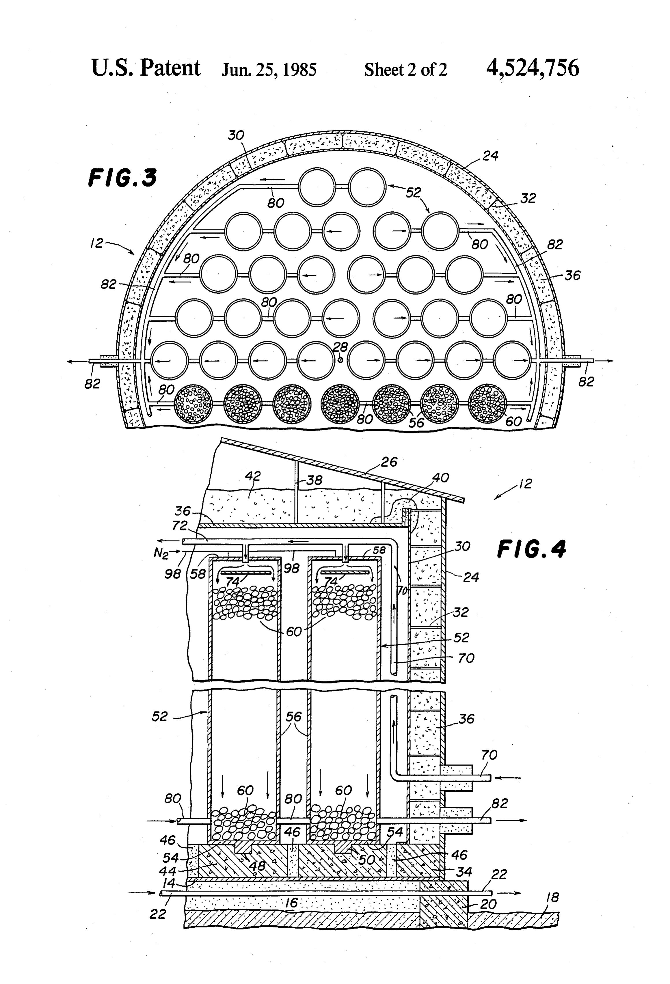
ing a thermally insulated tank having a bottom, side FIG. 2 is a partial sectional view taken along the line wall and roof; a plurality of spaced apart modular heat 2-2 of FIG. 1;
batteries inside the tank supported on load bearing ther FIG. 3 is a partial sectional view taken along the line mal insulation on the tank bottom; each heat battery 40 3-3 of FIG. 1; and constituting an enclosed metal shell containing a bed of FIG. 4 is an enlarged view of one side of the appara solid objects and around which objects a liquid can tus shown in FIG. 1, flow; conduit means to feed a hot or cold liquid from DETALED DESCRIPTION OF THE outside of the tank to the top of each bed in each bat DRAWINGS tery; and conduit means to withdraw a hot or cold 45 liquid from the bottom of each bed in each battery and To the extent it is reasonable and practical, the same deliver it to a destination outside of the tank. numbers will be used in the various views of the draw Each heat battery can be a vertical circular cylindri ings to identify the same or similar elements. cal shell with a flat bottom. Furthermore, the solid The thermal energy storage apparatus includes an objects in each battery can be rocks. 50 insulated tank 12 which has a flat metal circular bottom The tank desirably has a flat bottom and a vertical 14 supported on thermal insulation 16 resting on earth circular cylindrical side wall which supports the roof. 18. However, thermal insulation 16 can be replaced by The side wall thermal insulation can comprise a layer sand if insulating concrete blocks 44 described infra are of granular insulation supported between the side wall sufficiently thick to provide the required insulation. The and a thin gauge metal barrier which is suspended from 55 periphery of the tank is supported on circular concrete the side wall by a plurality of horizontal rods; and the foundation 20. A plurality of conduits 22 can be posi bottom insulation can comprise concrete load bearing tioned in the insulation 16 beneath tank bottom 14. insulation, such as in the form of blocks. When necessary or desirable, a cooling fluid, desirably The roof thermal insulation can be provided by a water, can be circulated through the conduits 22 to layer of granular insulation supported by a metal deck 60 prevent the earth 18 from becoming excessively hot and . suspended by rods from the roof. drying out to a depth such that earth shrinkage may The apparatus can also include means to flood the cause the tank to settle and fall. Of course, if the tank is tank with an inert gas for safety purposes. For the same based on rock rather than a soil containing water, such reason, means can be included to supply each battery cooling would not be required.
with a blanket of an inert gas. 65 The lower edge of vertical circular cylindrical tank Each battery bottom is desirably provided with side wall 24 is joined to the edge of tank bottom 14. means which maintains it axially stationary while per Conical roof 26 is mounted on the upper edge of side mitting radial expansion and contraction with tempera wall 24 and provides the main support for the roof.
Page 5
However, centrally positioned vertical column 28 pro The described thermal energy storage apparatus can vides additional support for the roof. be charged by feeding a previously heated stream of oil Internally spaced from side wall 24 is a thin gauge to conduit 70 which delivers it to branches 72. The hot metal vertical circular cylindrical barrier 30 which is oil is fed from branches 72 into each battery 52 simulta supported by a plurality of horizontal rods 32 extending 5 neously, consecutively or in any other suitable order at from the barrier to the side wall 24. The lower edge of a trickle rate such that the batteries are never full or barrier 30 is supported on an insulating concrete ring 34 flooded with oil. Filling the batteries with oil is undesir located on the top surface of tank bottom 14. The annu able because that is unnecessary and would use much lar space between the side wall 24 and the barrier 30 is more oil with an increase in capital investment. The use filled with a granular insulating material 36, desirably O of less oil is also a safety feature. As the hot oil runs perlite. down over the surface of the rocks 60, it collects in the Circular deck 36 is internally suspended by rods 38 bottom of each battery 52. The now-cooled oil is then from the inside of roof 26. The peripheral edge of deck withdrawn by branch conduits 80 and conduit 82, re 36 is located adjacent the upper edge of barrier 30. heated and returned or recycled to conduit 70. Insulating blanket 40 is placed over the edge of deck 36 5 As the hot oil flows downwardly over the surface of and the upper edge of barrier 30 to prevent granular the rocks, it will first heat the top layer of the rocks. A insulation from falling through the space between them. vertical temperature gradient, including a thermocline, Granular insulation 42, desirably perlite, is placed on will develop in each module. The thermocline will top of deck 36. involve a heat transfer zone above which are hot rocks A plurality of spaced apart circular blocks 44 of load 20 and below which are cold rocks. The heat transfer zone bearing insulating concrete are positioned on the top of will gradually move vertically downwardly as the heat tank bottom 14. The space between blocks 44 is filled from the hot oil is stored in the heat battery. Removal of with granular insulation 46, such as perlite. Each block heat from the oil cools it. Accordingly, cold oil flows 44 can have a central circular depression 48 in the top downwardly below the thermocline. The cold oil is into which a mating circular plate 50 fits. 25 removed from the bottom of the battery. When the heat Each circular block 44 supports a heat battery 52 zone reaches the bottom of the battery, it is fully having a flat metal circular bottom 54, a vertical circu charged with heat.
lar cylindrical metal wall 56 and a flat metal circular top To remove heat, cold oil is trickle fed simultaneously 58. Each battery is fully enclosed because it is undesir or consecutively into the top of one or more of the able for vapor from the liquid fed to the battery to 30 batteries. As the cold oil flows downwardly over the condense on the tank insulation. Plate 50 is joined to the bed of hot rocks, the oil is heated. A vertical tempera center of the outer surface of bottom 54 so as to permit ture gradient, including a downwardly moving thermo it to expand and contract equally in all radial directions. cline heat transfer zone, develops in which the cold oil This permits each battery 52 to remain axially station is located above the Zone and hot oil is located below ary. 35 the zone. The hot oil is then collected and drained from Each heat battery 52 is filled with solid objects such the bottom of each battery and pumped to the location as rocks 60 or some other material which can store heat. where the heat is desired. Thus, a plurality of small metal cylindrical containers The oil used should be of suitable quality for the containing a solidified salt which melts when heated can range of temperatures intended. In particular, it should also be used in the batteries 52 to store heat. Whatever 40 be a low vapor pressure, high flash oil which will not material is used, space must be provided between the decompose over the intended operating temperature solid objects so that a liquid can readily flow through range. An oil having a vapor pressure less than atmo each battery from top to bottom. spheric pressure at the maximum temperature in the Two conduits 70 run through opposite sides of the heat storage battery is preferred. Since the oil will have wall of the tank 12 and extend to above the top of bat 45 a true vapor pressure much less than atmospheric, the teries 52. Conduits 70 then branch into a plurality of nitrogen blanket maintains the pressure in the heat bat conduit arms 72 which communicate with the top cen teries at essentially atmospheric pressure. ter of the batteries 52. A liquid is supplied to the batter Instead of using oil, a molten salt heat transfer me ies individually or simultaneously by means of conduits dium can be used. The vapor pressure of the molten salt 70 and 72. Each battery can be provided with a baffle 74 50 should be less than atmospheric pressure at the maxi in the upper part to facilitate uniform distribution of the mum temperature in the heat storage battery. liquid as it flows down through rocks 60. The foregoing detailed description has been given for Liquid withdrawal branch conduits 80 communicate clearness of understanding only, and no unnecessary with the bottom interior of each battery 52. The branch limitations should be understood therefrom, as modifi conduits 80 in turn communicate with two main liquid 55 cations will be obvious to those skilled in the art. withdrawal conduits 82, each of which extends out What is claimed is:
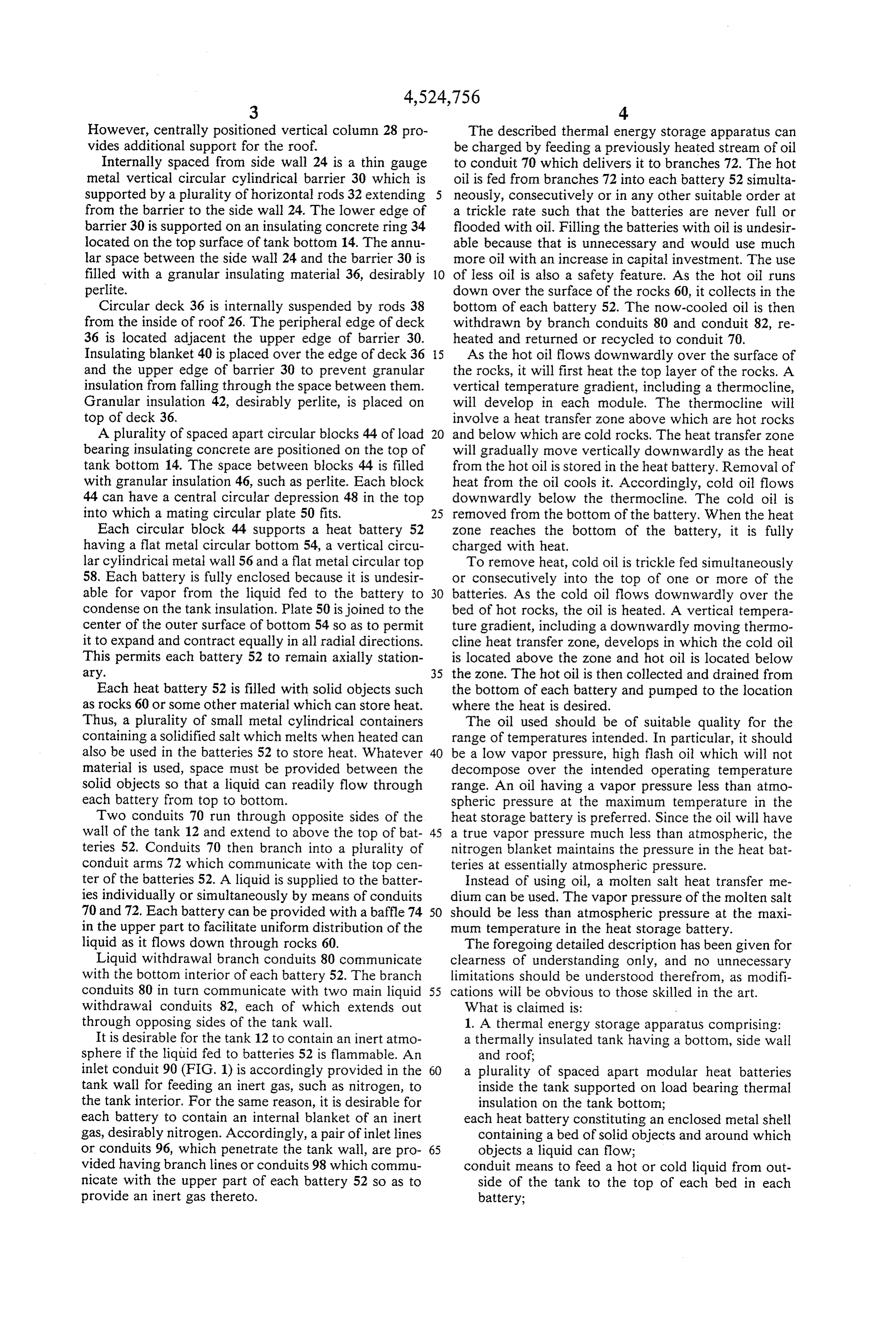
through opposing sides of the tank wall. 1. A thermal energy storage apparatus comprising: It is desirable for the tank 12 to contain an inert atmo a thermally insulated tank having a bottom, side wall sphere if the liquid fed to batteries 52 is flammable. An and roof;
inlet conduit 90 (FIG. 1) is accordingly provided in the 60 a plurality of spaced apart modular heat batteries tank wall for feeding an inert gas, such as nitrogen, to inside the tank supported on load bearing thermal the tank interior. For the same reason, it is desirable for insulation on the tank bottom; each battery to contain an internal blanket of an inert each heat battery constituting an enclosed metal shell gas, desirably nitrogen. Accordingly, a pair of inlet lines containing a bed of solid objects and around which or conduits 96, which penetrate the tank wall, are pro 65 objects a liquid can flow; vided having branch lines or conduits 98 which commu conduit means to feed a hot or cold liquid from out nicate with the upper part of each battery 52 so as to side of the tank to the top of each bed in each provide an inert gas thereto. battery;
Page 6
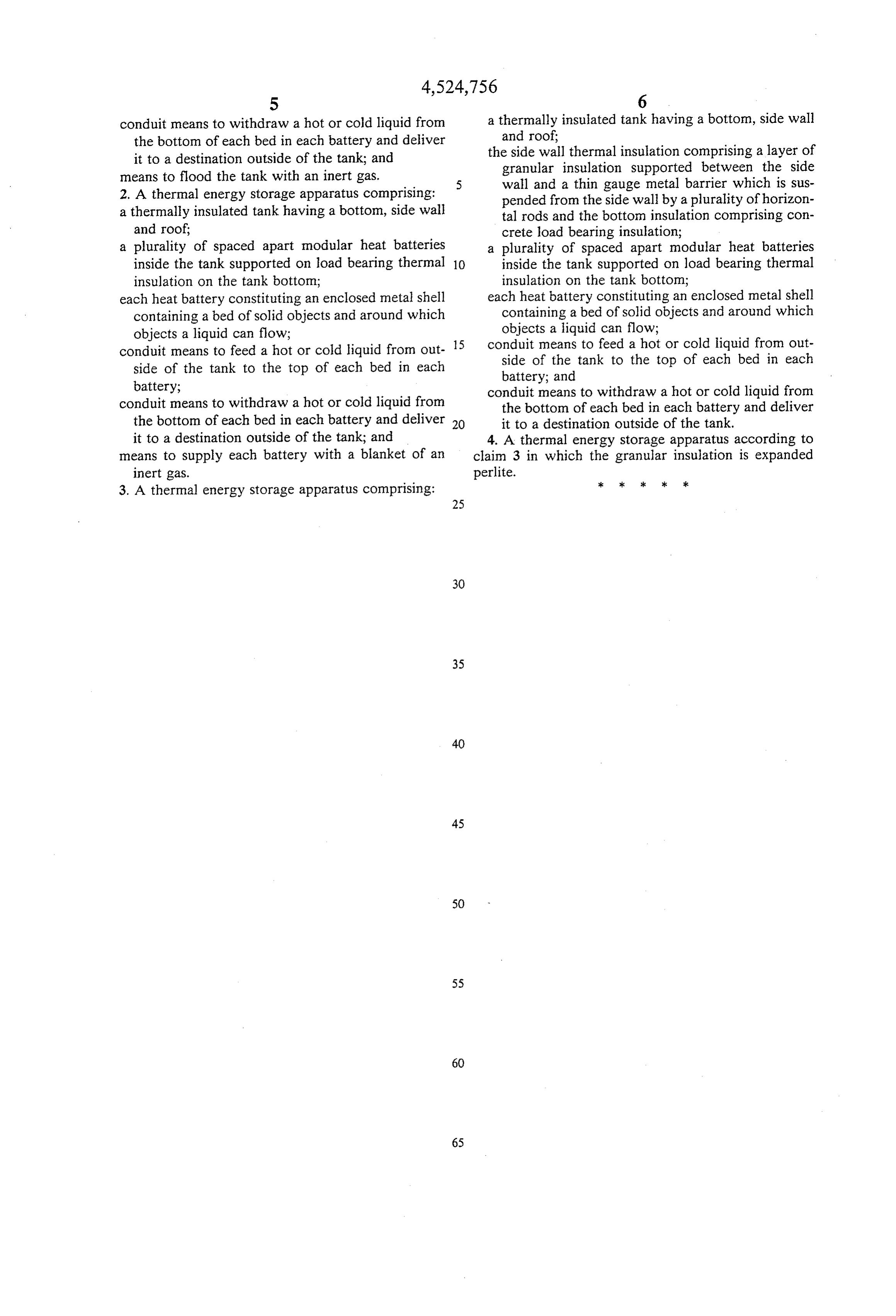
conduit means to withdraw a hot or cold liquid from a thermally insulated tank having a bottom, side wall the bottom of each bed in each battery and deliver and roof it to a destination outside of the tank; and the side wall thermal insulation comprising a layer of means to flood the tank with an inert gas. granular insulation supported between the side 2. A thermal energy storage apparatus comprising: wall and a thin gauge metal barrier which is sus pended from the side wall by a plurality of horizon a thermally insulated tank having a bottom, side wall tal rods and the bottom insulation comprising con and roof; crete load bearing insulation; a plurality of spaced apart modular heat batteries a plurality of spaced apart modular heat batteries inside the tank supported on load bearing thermal 10 inside the tank supported on load bearing thermal insulation on the tank bottom; insulation on the tank bottom; each heat battery constituting an enclosed metal shell each heat battery constituting an enclosed metal shell containing a bed of solid objects and around which containing a bed of solid objects and around which objects a liquid can flow; objects a liquid can flow; conduit means to feed a hot or cold liquid from out 15 conduit means to feed a hot or cold liquid from out side of the tank to the top of each bed in each side of the tank to the top of each bed in each battery; battery; and conduit means to withdraw a hot or cold liquid from conduit means to withdraw a hot or cold liquid from the bottom of each bed in each battery and deliver the bottom of each bed in each battery and deliver 20 it to a destination outside of the tank. it to a destination outside of the tank; and 4. A thermal energy storage apparatus according to means to supply each battery with a blanket of an claim 3 in which the granular insulation is expanded inert gas. perlite.
3. A thermal energy storage apparatus comprising: ck xk sk sk sk
Page 7
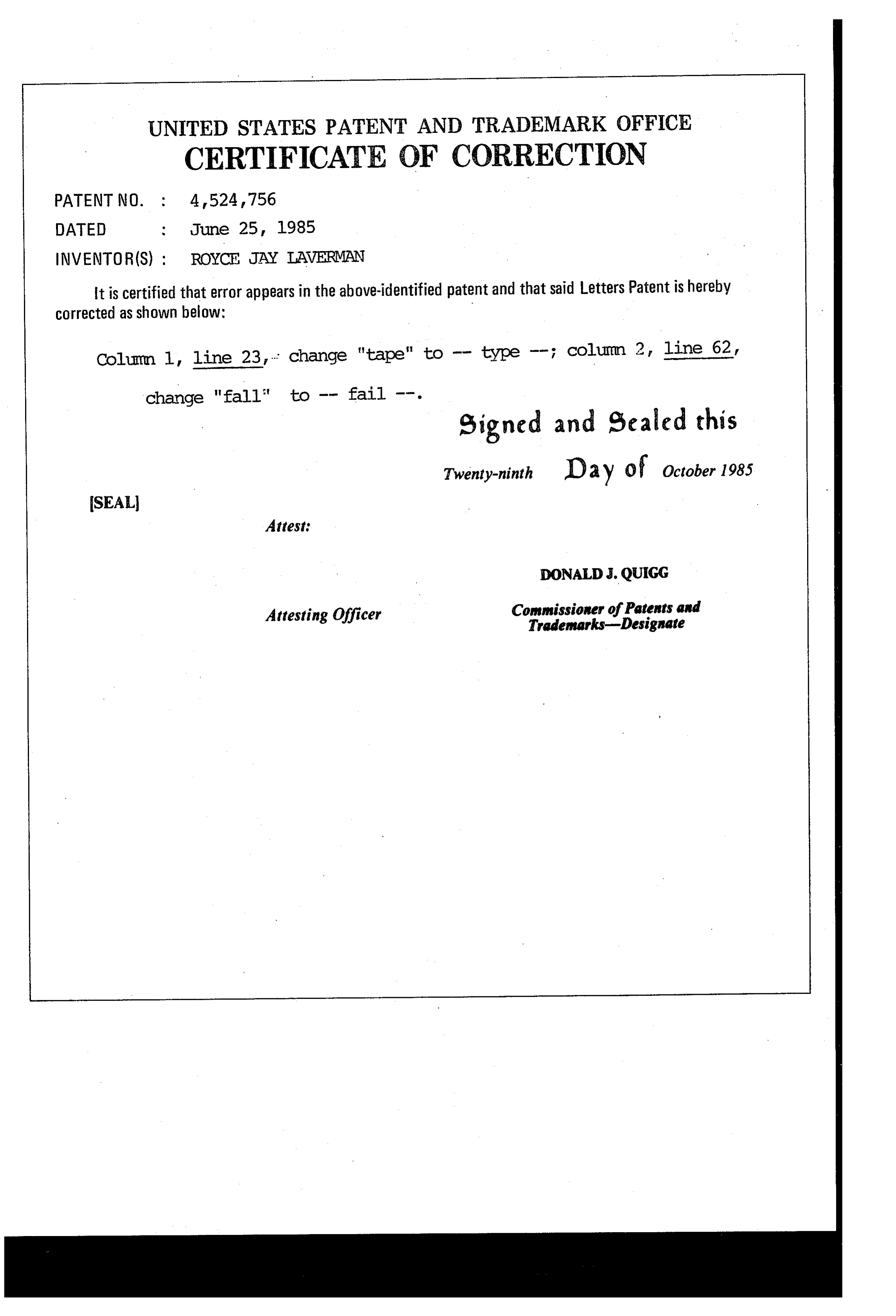
UNITED STATES PATENT AND TRADEMARK OFFICE
CERTIFICATE OF CORRECTION
INVENTOR(S) : ROYCE JAY LAVERMAN
It is certified that error appears in the above-identified patent and that said Letters Patent is hereby Corrected as shown below:
Column 1, line 23, . . change "tape" to type ; Column 2, line 62, change "fall" to -- fail --.
eigned and Sealed this
Twenty-ninth D 2 y O f October 1985
SEAL
Attest:
DONALDJ. QUIGG
Attesting Officer Commissioner of Patents and
Provenance
- Collection
- Cited prior art
- Original PDF
- patentimages.storage.googleapis.com →
- Filed
- 1983-07-25
- Pages
- 7
- Method
- pdftotext (the PDF's own text layer) + pdftoppm 300dpi page scans
- Source
- Google Patents bibliographic record
- Granted
- 1985-06-25
- Inventors
- Royce J. Laverman; Chicago Bridge and Iron Co
- Transcribed from
- patentimages.storage.googleapis.com →