patent · US4182409
Heat transfer system
8 January 1980
Page 1 — bibliographic record
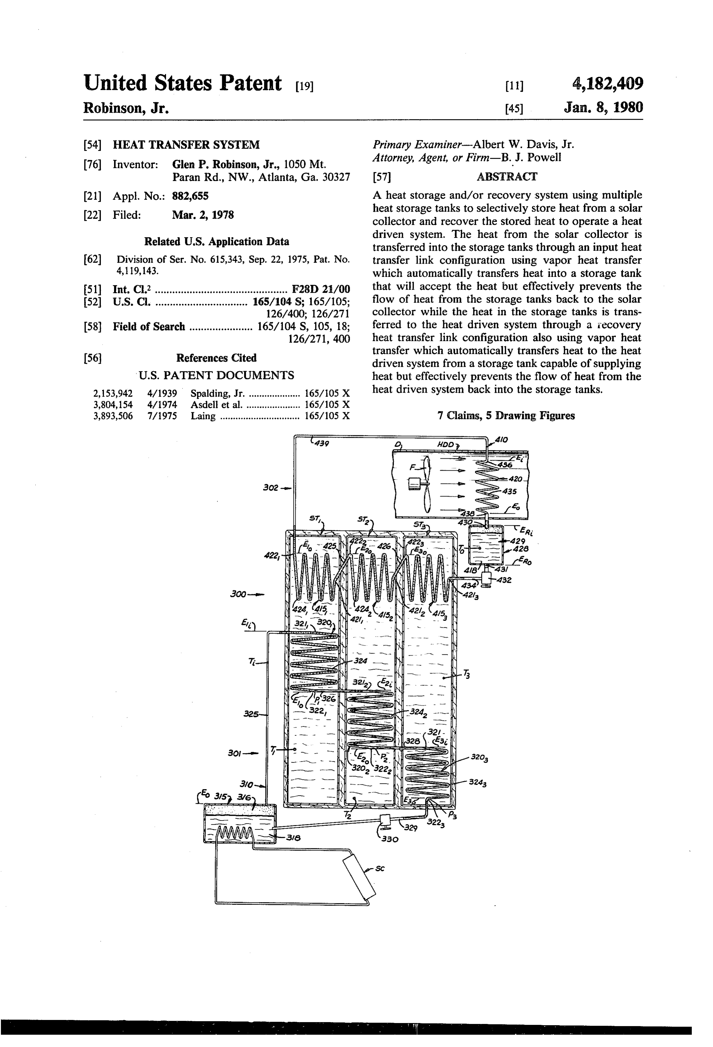
United States Patent (19) (11) 4,182,409 Robinson, Jr. 45) Jan. 8, 1980 54 HEAT TRANSFER SYSTEM Primary Examiner-Albert W. Davis, Jr. 76) Inventor: Glen P. Robinson, Jr., 1050 Mt. Attorney, Agent, or Firm-B.J. Powell Paran Rd., NW., Atlanta, Ga. 30327 57 ABSTRACT 21) Appl. No.: 882,655 A heat storage and/or recovery system using multiple 22 Filed: Mar. 2, 1978 heat storage tanks to selectively store heat from a solar collector and recover the stored heat to operate a heat
Related U.S. Application Data driven system. The heat from the solar collector is transferred into the storage tanks through an input heat 62 Division of Ser. No. 615,343, Sep. 22, 1975, Pat. No. transfer link configuration using vapor heat transfer 4,119,143. which automatically transfers heat into a storage tank 51 Int. C.’.............................................. F28D 21/00 that will accept the heat but effectively prevents the 52 U.S. Cl. ................................ 165/104 S; 165/105; flow of heat from the storage tanks back to the solar 126/400; 126/271 collector while the heat in the storage tanks is trans (58) Field of Search ...................... 165/104 S, 105, 18; ferred to the heat driven system through a recovery 126/271, 400 heat transfer link configuration also using vapor heat transfer which automatically transfers heat to the heat (56 References Cited driven system from a storage tank capable of supplying
2,153,942 4/1939 Spalding, Jr. .................... 165/105 X heat driven system back into the storage tanks. 3,804,154 4/1974 Asdell et al. ... ... 165A105 X 3,893,506 7/1975 Laing.............. -a 165/105 X 7 Clains, 5 Drawing Figures
Page 2
Drawing sheet — no readable text.
Page 3
Drawing sheet — no readable text.
Page 4
Drawing sheet — no readable text.
Page 5
of large quantities of heat from the heat output of the
HEAT TRANSFER SYSTEM solar collector to the heat storage tank as long as the CROSS REFERENCE TO RELATED heat output from the solar collector is slightly higher than the temperature of the heat storage tank but sub
APPLICATION 5 stantially prevents the flow of heat from the storage
This application is a division of my co-pending appli tank back into the solar collector when the temperature cation Ser. No. 615,343 filed Sept. 22, 1975, now U.S. of the storage tank is substanitially equal or higher than Pat. No. 4,119,143, granted Oct. 10, 1978. the temperature of the solar collector. The heat transfer
BACKGROUND OF THE INVENTION
link acts as a heat check valve to allow the heat from the
heat source to flow into the heat sink but prevents the
As the resources of combustible fuels to supply en reverse flow of heat from the heat sink back into the ergy for heating, cooling and electricity are becoming heat source. Various combinations of these heat transfer more depleted, considerable interest has been generated links can be used to provide a multiple storage tank in the use of solar energy to satisfy these requirements. 15 system with the capability of storing heat at different The ability of a solar powered system to effectively temperatures without the use of temperature sensors, utilize solar energy in a reliable and economical manner mechanical valves or control systems. depends in large part on (1) its ability to efficiently store A similar heat transfer link can be used to provide a large quantities of heat during the limited number of heat recovery system from the heat storage tanks. By hours of available sunlight in order to operate the sys tem during the time in which sunlight is not available; 20 ausing various combinations of these heat transfer links, heat recovery system for recovering heat from multi and (2) its ability to efficiently store heat at the highest ple heat storage tanks at different temperatures can be possible temperature over a relatively wide range of provided without the use of temperature sensors, me collection temperatures during the available hours of chanical valves or control systems. sunlight.
Because water has proved to be one of the most eco- 25 transfer The heat transfer link of the invention is adapted to nomical storage mediums available from the present substantially heat from a source of heat to a heat sink while state of the art, most prior art solar energy storage sys preventing the transfer of heat from the tems use water as the storage medium. Since the amount heat sink back to the source of heat. The heat transfer of heat that can be stored in a fixed quantity of water is link includes a first heat exchange means carrying a directly proportional to its temperature, it is desirable to 30 working fluid with a prescribed vaporization tempera have the water at the highest temperature possible in ture and pressure range where the first heat exchange order to keep the quantity of water required for storage means is located at a first elevation and places the work at a minimum. On the other hand, because a single hot ing fluid therein in a heat exchange relationship with the water storage tank can absorb heat only when the tem heat output of the source of heat to vaporize the work perature from the solar collector is higher than the 35 ing fluid. The heat transfer link also includes a second temperature of the water in the storage tank and be heat exchange means located at a second elevation cause the available temperature at the solar collector higher than the first elevation and connected to the first varies significantly over the normal hours of available heat exchange means for receiving the vaporized work sunlight, it is desirable to use multiple storage tanks ing fluid from the first heat exchange means and return which permit shifting the heat storage to another tank ing condensed working fluid to the first heat exchange when one of the tanks will not absorb any more heat means under the force of gravity. The second heat ex from the solar collector. change means places the vaporized working fluid in a Multiple water storage tank systems have been pro heat exchange relationship with the heat sink so that the posed where the solar collector is connected to the heat sink appropriate storage tank through temperature con 45 ing fluid towillcondense absorb the heat from the vaporized work trolled mechanical valves. These systems require that heat sink is below theittemperatureas long as the temperature of the both the temperature of the heat output from the solar As the vaporized working fluid of the source of heat. collector and the temperatures of the water in the tanks densed working fluid flows back to the first the condenses, con heat ex be sensed, and that an appropriate control system be changer means under the force of gravity to be re-vapo provided so that the mechanical valves can be se- 50 quenced to transfer the solar collector heat output from rized. For a heat storage system, the source of heat may be one storage tank as its temperature approaches that of the output from the solar collector to another storage the heat output of the solar collector and the heat sink tank which will accept the heat output. This has neces may be a plurality of storage tanks, usually filled with sarily required these systems to be complex and thus 55 water. For a heat recovery system, the source of heat is expensive to build and operate. Similar systems have usually the plurality of storage tanks, usually filled with been proposed which provide for the recovery of usable water, while the heat sink is usually a heating system, a heat from these storage tanks, however, such heat re heat driven cooling system or some other heat driven covery systems have suffered from the same drawbacks system.
as the prior art storage systems. 60 For a heat storage system, if the heated output from the heat source is serially through multiple heat transfer
SUMMARY OF THE INVENTION links individually connected to multiple heat storage These and other problems and disadvantages associ tanks, then the first most upstream tank will be heated ated with the prior art are overcome by the invention first followed successively by the downstream tanks. If disclosed herein by providing a heat transfer link that 65 a single heat transfer link is used with series connected connects the heat output from a heat source such as a output heat exchanges individually associated with mul solar collector to a heat sink capable of receiving heat tiple heat storage tanks, substantially the same result can such as a heat storage tank which allows rapid transfer be achieved.
Page 6
For a heat recovery system using multiple heat stor perature of the working fluid as will become more ap age tanks, if the operating fluid of the heat sink is passed parent.
serially through multiple heat transfer links individually The heat transfer link 10 also includes an output heat connected to the storage tanks so that the lowest tem exchanger 20 which has an upper end 21 and a lower perature tank is the most upstream, then the highest end 22. The output heat exchanger 20 defines a heat temperature can be maintained in the operating fluid for transfer chamber 24 therein which receives the vapor the longest period of time. If a single heat transfer link ized working fluid 18 therein and places this vaporized is used with series connected input heat exchangers working fluid in a heat exchange relationship with the individually associated with multiple heat storage tanks, heat sink 12. The lower end 22 of the output heat ex the heat may be sequentially recovered from the storage 10 changer 20 is located at a second elevation E2 higher tanks starting with either the highest or lowest tempera than the first elevation and the lower end 22 of the heat ture tank first. transfer chamber 24 in output heat exchanger 20 is con These and other features and advantages of the inven nected through transfer pipe 25 to the upper end 17 of tion will become more apparent upon consideration of the fluid reservoir 16 in input heat exchanger 15. The the following specification and accompanying drawings 5 upper end 21 of the heat transfer chamber 24 in output wherein like characters of reference designate corre heat exchanger 20 is closed. The fluid chamber 16, the sponding parts throughout the several views and in pipe 25, and the heat transfer chamber 24 define a closed which: system and this system is charged with working fluid 18 BRIEF DESCRIPTION OF THE DRAWINGS 20 so that pipe 25 and chamber 24 are filled with vaporized working fluid when no heat is being transferred from
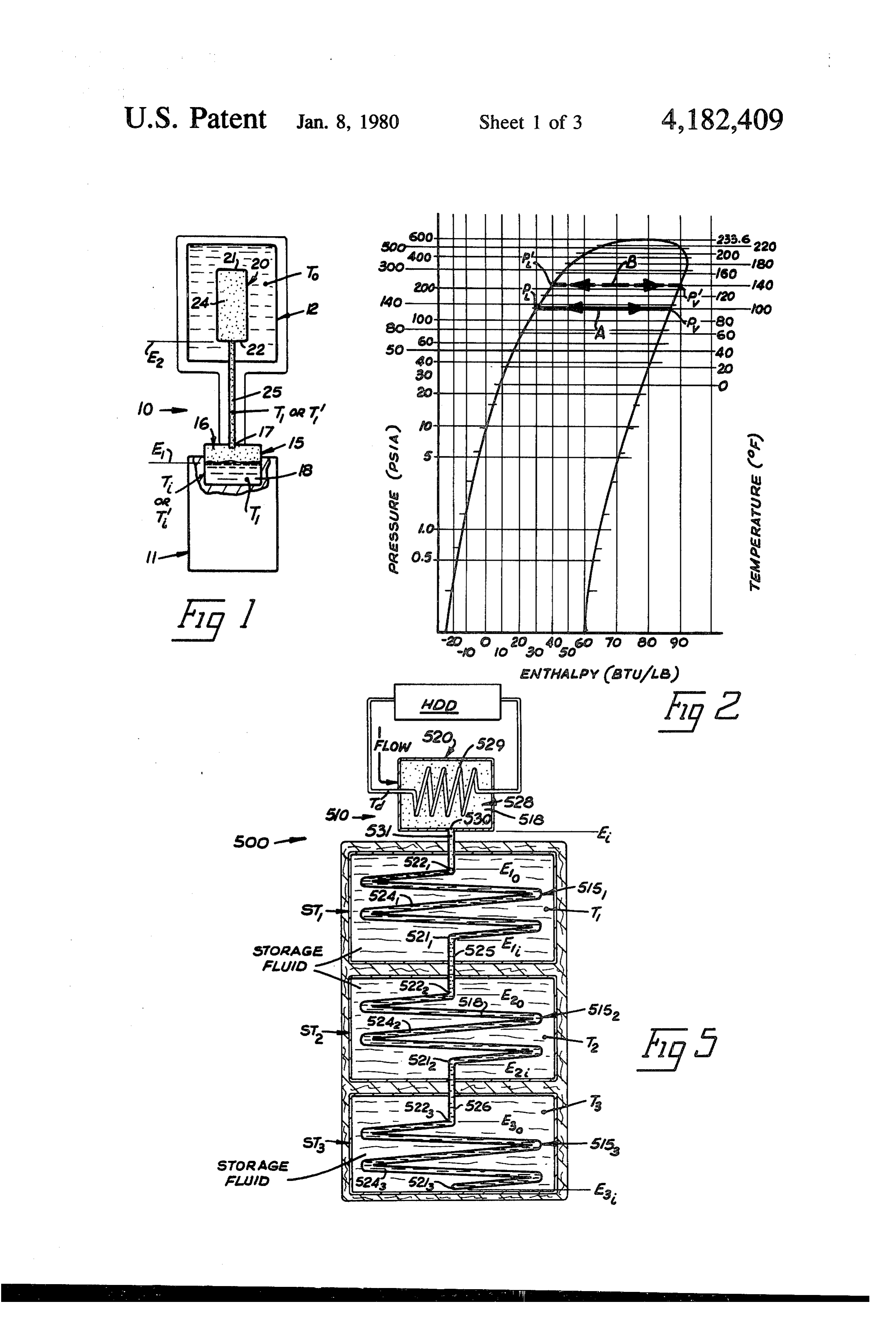
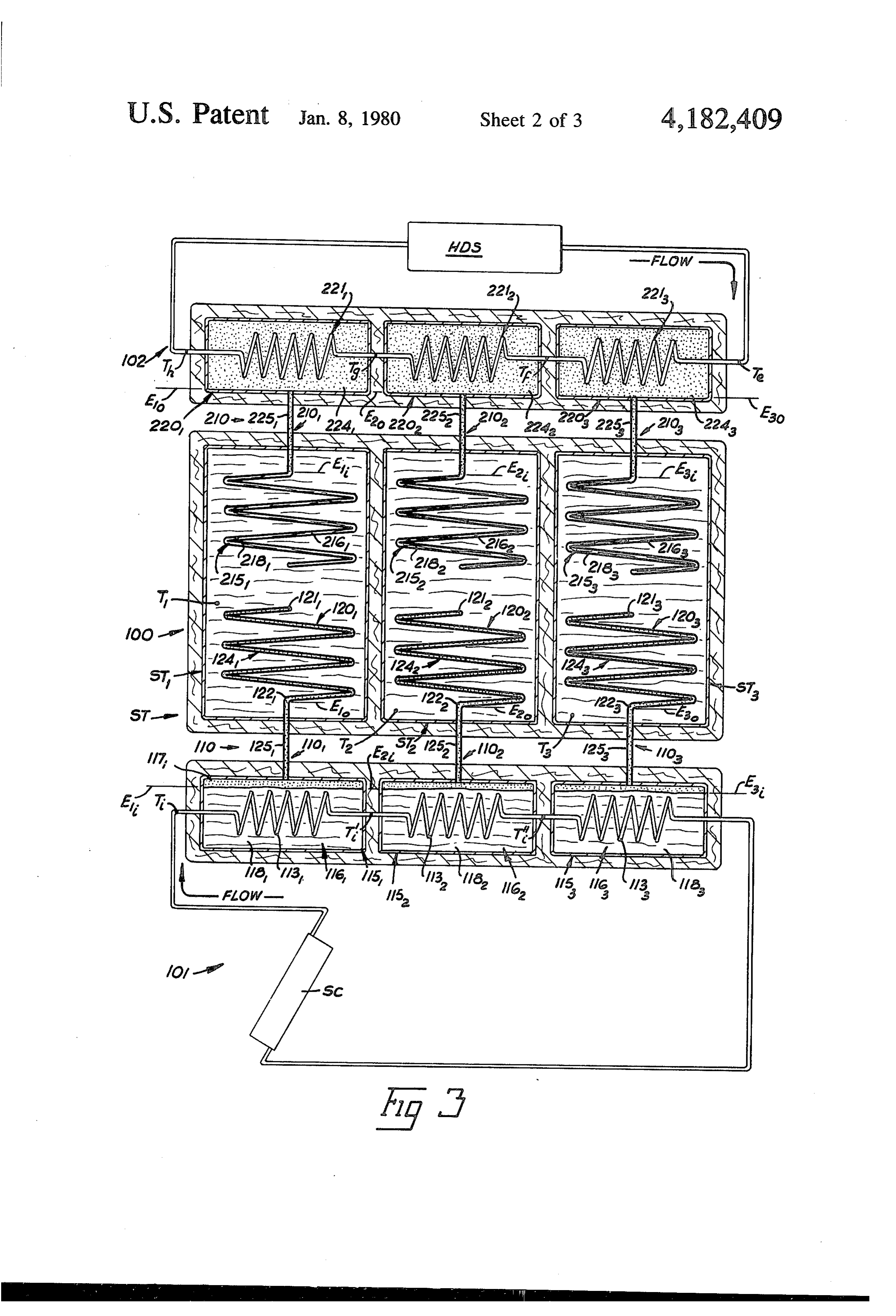
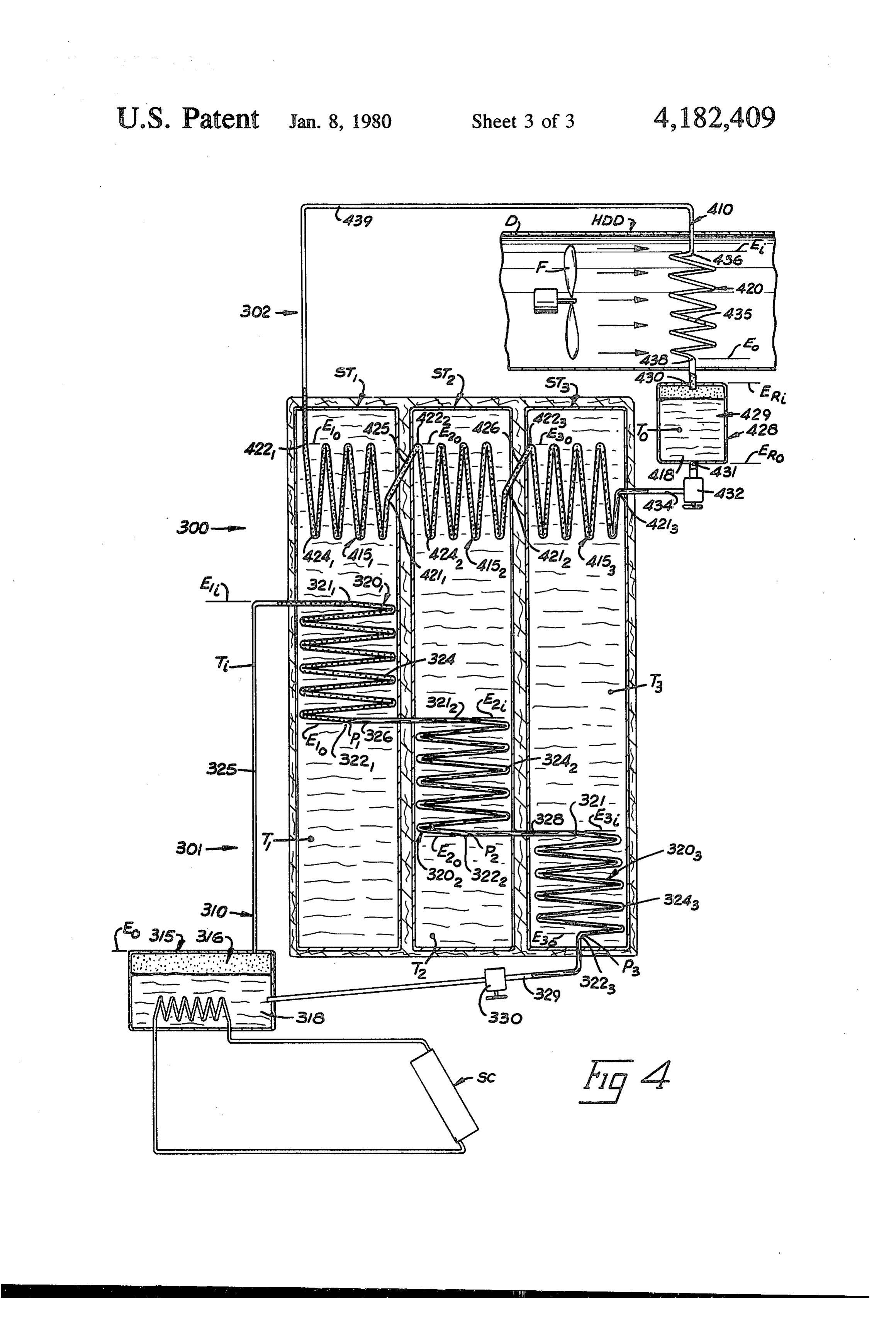
FIG. 1 is a schematic drawing illustrating one of the input heat exchanger 15 to output heat exchanger 20. heat transfer links of the invention; In operation, the fluid chamber 16, the pipe 25 and FIG. 2 is a saturated pressure-enthalpy curve for a the heat transfer chamber 24 are charged with the typical refrigerant; working fluid 18 at a prescribed pressure when the FIG. 3 is a schematic drawing illustrating one em 25 temperature of the working fluid is at a known tempera bodiment of a heat storage and recovery system of the ture. The initial charging pressure is selected to cause invention; the working fluid 18 in the input heat exchanger 15 to FIG. 4 is a schematic drawing illustrating another start boiling to vaporize the liquid working fluid when embodiment of a heat storage and recovery system of 30 the available temperature from the heat source 11 rises the invention; and, above a prescribed value to start the operation of the FIG. 5 is a schematic drawing illustrating still an heat transfer link 10.
other heat recovery system of the invention. Assuming initially that the temperature Ti of the heat These figures and the following detailed description source 1 is the same as the temperature T of the heat disclose specific embodiments of the invention, how 35 sink 12, the working fluid 18 in a liquid state will partly ever, it is to be understood that the inventive concept is fill the reservoir 16 in the input heat exchanger 15. The not limited thereto since it may be embodied in other rest of reservoir 16, the pipe 25 and the heat transfer forms. chamber 24 will be filled with the working fluid 18 in a DETAILED DESCRIPTION OF ILLUSTRATIVE vapor state. The temperature Ti and pressure Pi of the EMBODIMENTS liquid and vapor of the working fluid 18 will be substan tially constant throughout both heat exchangers 15 and
Referring to FIG. 1, the heat transfer link 10 is con 20 and the pipe 25. The temperature TI will be equal to nected between a heat source 11 and a heat sink 2 and temperatures Ti and To and the vapor phase of working is in a heat exchange relationship with both. The heat fluid 18 will be in equilibrium with the liquid phase transfer link 10 operates to transfer heat from the heat 45 thereof. Because there are no temperature differences source 11 to the heat sink 12 but prevents the transfer of between the heat source 11 and heat sink 12, no heat heat from the heat sink 12 back to the heat source 11. will be transferred and the system will be at a steady Thus, the heat transfer link 10 is a one direction heat state. When the output temperature Ti of the heat transfer device as will become more apparent. source 11 rises to temperature T above the tempera The heat transfer link 10 comprises an input heat 50 ture To of the heat sink 12, the working fluid 18 in its exchanger 15 including a fluid reservoir 16 with an liquid phase will start to boil. This causes the working upper end 17. The fluid reservoir 16 is charged with a fluid 18 to absorb heat and increase its enthalpy. Thus, working fluid 18 which has a prescribed vaporization the heat source 1i is now trying to drive the tempera temperature and pressure relationship so that the liquid ture Tt of the working fluid 18 toward the higher tem level of the working fluid has elevation E1. While a 55 perature T of the heat source 11 by vaporizing liquid number of different working fluids may be used as long working fluid while the heat sink 12 is trying to drive as the working fluid can be vaporized at the minimum the temperature Ti toward the lower temperature To of operating temperature of the heat source 11, refriger the heat sink 12 by condensing vapor working fluid. ants normally used in air conditioning systems such as This generates a slight pressure difference in the vapor Refrigerant 12 have been found satisfactory when heat 60 working fluid 18 between exchanger 15 and exchanger is being received from a solar collector, especially 20 so that a net vapor flow is generated between the where the heat source working fluid is water and the exchangers 15 and 20 driving the vapor and thus the heat sink working fluid is water. The input heat ex heat energy toward exchanger 20. The temperature of changer 15 places the working fluid 18 in a heat ex the working fluid 18 will rise to a higher temperature changer relationship with the heat output of the heat 65 Ti with a corresponding rise in pressure to pressure Pf source 11 so that the working fluid in reservoir 16 will where the liquid and vapor phases again reach equilib be vaporized when the temperature of the heat output rium but the pressure and temperature will still be virtu from the heat source 11 exceeds the vaporization tem ally constant throughout the system.
Page 7
The temperature To of the heat sink 12 is now below would no longer be vaporized since the pressure of the the temperature Tf of the working fluid vapor in the vapor working fluid 18 would be equal to or greater output heat exchanger 20 so that the latent heat in work than the equilibrium vapor pressure of the liquid work ing fluid 18 is transferred to the heat sink 12 to decrease ing fluid 18 in the input heat exchanger 15. All of the the enthalpy of the working fluid vapor causing it to 5 condensed liquid working fluid 18 will now drain back start to condense to its liquid phase. Because the liquid into the input heat exchanger 15 and not vaporize. working fluid 18 in the output heat exchanger 20 is at When the temperature T reduces to a value less than substantially the same temperature Ti" as the vaporized temperature To some of the vapor working fluid 18 will working fluid 18, virtually no heat transfer takes place condense until a new lower equilibrium pressure is between the liquid and vapor as the condensed liquid 10 reached. However, since there is now no liquid working working fluid 18 flows back by gravity to the input heat fluid 18 in the output heat exchanger 20, the higher exchanger 15 through pipe 25. As the vapor in the out temperature Tain the heat sink 12 can produce no vapor put heat exchanger 20 is condensed, more of the liquid in the working fluid 18 and there will consequently be in the input heat exchanger 15 is vaporized to replace no heat transferred through the working fluid 18 in the the condensed vapor. Thus, it will be seen that heat will 15 reverse direction from the heat sink 12 to the heat be continuously transferred from the output of the heat source 11 except for a small amount of heat flow caused source 11 to the working fluid 18 through the input heat by conduction through pipe 25 and by convection exchanger 15 while heat will be continuously trans through the vapor working fluid 18 in pipe 25. Thus, the ferred from the working fluid 18 to the heat sink 12 heat transfer link 10 effectively transfers heat only from through the output heat exchanger 20 as long as the 20 the heat source 11 to the heat sink 12 and not in the actual temperature T of the heat sink 12 remains reverse direction.
below the temperature T of the output of the heat FIRST EMBODIMENT OF HEAT STORAGE source 11. The heat transfer rate from the heat source 11 to the heat sink 12 through the heat transfer link 10 is, of AND RECOVERY SYSTEM course, proportional to the temperature difference be- 25 FIG. 3 illustrates a heat storage and recovery system tween the heat source 11 and heat sink 12 with greater 100 which uses a plurality of heat transfer links to store temperature differences producing greater heat transfer and recover heat at different temperature levels. This rates. Because the latent heat of the working fluid 18 is system is especially adaptable to store heat from a solar used as the heat transfer mechanism, the heat transfer collector SC that acts as the heat source for the storage rate capability of link 10 is several times greater than a 30 loop 101 of the system. The solar collector SC has a heat transfer mechanism that does not use vaporization heated fluid output, usually water, whose heat is trans and condensation. ferred to a plurality of insulated storage tanks ST with Reference to FIG. 2, which is a saturation pressure a storage fluid therein, usually water. These storage enthalpy curve for a typical refrigerant such as Refrig tanks ST act as the heat source in the heat recovery erant 12 (Freon-12, a trademark of DuPont de Nemours 35 loop 102 of the system. The heat in the storage tanks ST Co.), will better explain the pressure and temperature is transferred to a heat driven system HDS such as a relationships of the heat transfer. Because the working heater or heat driven air conditioner to drive the sys fluid 18 changes from its liquid to its vapor phase and tem. While different numbers of storage tanks ST may back to its liquid phase at a substantially constant pres be used, three are illustrated and individually desig sure and temperature under saturation conditions, it will nated ST1, ST2 and ST3.
be seen that heat is transferred while the working fluid The system heat input loop 101 includes a separate 18 remains at a substantially constant temperature. For storage heat transfer link 110 transferring heat from the instance, assume that heat is being transferred into the output fluid of the solar collector SC to one of the heat transfer link from the heat source and the equilib storage tanks ST. The heat transfer links are individu rium temperature of the working fluid in the link is 100 45 ally numbered 1101, 1102 and 1103 to correspond to the F. The heat being transferred into and out of the link storage tank into which each transfers heat from the working fluid is represented by the solid line A in FIG. solar collector. Since each of the storage heat transfer . 2 extending between point PL on the saturated liquid links 110 have the same construction, only link 110 will side of the curve and P on the saturated vapor side of be described in detail with corresponding reference the curve. Now, suppose the temperature of the heat 50 numbers being applied to links 1102 and 1103. source imposed on the heat transfer link is increased. The input heat exchanger 1151 of link 1101 is a shell This raises the equilibrium temperature of the working and tube type heat exchanger where the working fluid fluid in the link to 140 F. as an example. The heat being 118 of the link is carried in the shell chamber 116 while transferred into and out of the link working fluid is now the heated fluid output from the solar collector SC represented by dashed line B extending between point 55 passes through the tubes 1131 of exchanger 1151 to heat PL" on the saturated liquid side of the curve and point the working fluid 1181. The output heat exchanger 120 P' on the saturated vapor side of the curve. As the is a coil vertically oriented and immersed in the storage temperature of the heat source rises, it will be seen that fluid in tank ST1. The passage 1241 in coil 1201 is closed both the pressure and temperature of the working fluid at its upper end 121 while its lower end 1221 is con 18 rise, however, the higher pressure and temperature nected to the vapor space in the shell of heat exchanger are substantially constant throughout the working fluid 1151 through the transfer pipe 1251. It will thus be seen 18. that the link 1101 will transfer heat from the heated fluid When the temperature To of the heat sink 12 equals output from the solar collector SC passing through tube the temperature T of the heat source 11 or the tempera 113, to the storage fluid in tank ST in the manner de ture T of the heat source 11 falls below the temperature 65 scribed for link 10 but will not transfer significant heat To of the heat sink 12 as would occur with a solar collec in the reverse direction from the storage fluid in the tor heat source over a period of daily operation, the storage tank to the fluid output from the solar collector. liquid working fluid 18 in the input heat exchanger 15 The level of the liquid working fluid in the shell cham
Page 8
ber 1161 is at the lower elevation Eli while the lower temperature T from the solar collector SC may drop end 1221 of coil 120 is located at the higher elevation below the temperature T in the storage tank ST while E1a so that the working fluid 1181 condensed in coil the temperature will still remain higher than the temper 1201 will flow back to the shell chamber 1161 in ex ature T2 or T3 in tanks ST2 or ST3. Because of the one changer 1151 through pipe 1251 under the influence of 5 way action of each of the heat transfer links 110, the gravity. Normally, the pipe 1251 will be insulated. heated fluid output from the solar collector SC will pass It will be noted that the heated fluid output from the through those heat transfer links associated with the solar collector SC passes serially through the tubes storage tanks ST at a temperature higher than the tem 1131, 1132 and 1133 of the heat exchangers 1151, 1152 and perature Ti without transferring heat to the particular 153 of the heat transfer links 110, 1102 and 103. Thus, 10 storage tank. As soon as this heated fluid output reaches the heated fluid output from solar collector SC passes the heat transfer link 110 associated with the upstream through the tube 1131 in link 1101 first, then through most storage tank ST at a lower temperature than the tube 1132 in link 1102, and finally through the tube 1133 temperature Ti, heat will be transferred through the in link 1103 before it is recycled through the solar col heat transfer link 110 into that storage tank ST until the lector SC for reheating. 15 temperature of the storage fluid in that particular stor The system heat input loop 101 of the system 100 age tank rises to or exceeds the temperature Ti. Nor operates with the transfer links 1101-1103 each transfer mally the temperature T will be greater than the tem ring heat to its associated storage tank under the theory perature T2 and the temperature T2 will be greater than of operation described hereinabove for link 10. Assum the temperature T3. If the temperature Tifalls below all ing that the storage tank ST is at an initial temperature 20 of the temperatures at the storage tanks, the fluid output T1, that the storage tank ST2 is at an initial temperature from the solar collector will flow through all of the T2 and that the storage tank ST3 is at an initial tempera input heat exchangers 115 without heat being trans ture T3, the system operation will be described where ferred to any of the associated storage tanks ST. When the input temperature T from the solar collector heat the input temperature Ti again rises above any of the source SC is at a higher temperature of any of the tanks 25 temperatures of the storage fluids in the storage tanks, ST. The heated fluid output from the solar collector SC heat will be transferred through the associated link 110 passes first through the tube 1131 in the input heat ex into the storage fluid in the most upstream storage tank changer 1151 of the first heat transfer link 1101 where whose temperature is below the temperature T. the working fluid 1181 in the heat transfer link 1101 is The heat recovery loop 102 includes a separate re vaporized thereby absorbing heat and transfering heat 30 covery heat transfer link 210 connecting each storage from the heated fluid output of collector SC to the tank with the driving fluid of a heat driven system storage tank ST1. This causes the heated fluid output HDS. The recovery heat transfer links 210 are individu from the solar collector SC to be cooled to a new lower ally numbered 2101, 2102 and 2103 to correspond to the temperature T by the time it passes to the next heat storage tank each connects to the driving fluid of the transfer link 1102. If this new temperature T is higher 35 heat driven system HDS. Since each of the recovery than the temperature T2 of the storage tank ST2, then heat transfer links 210 have the same construction, only heat will also be transferred through the heat transfer link 2101 will be described in detail with corresponding link 1102 to cool the heated fluid output from the collar reference numbers being applied to links 2102 and 2103. collector SC to a still lower temperature T" by the time The input heat exchanger 2151 of link 2101 is a coil it passes to the third heat transfer link 1103. If the tem- 40 vertically oriented and immersed in the storage fluid in perature Ti" is higher than the temperature T3 in the tank ST1. The working fluid 2181 of the link is carried in storage tank ST3, then additional heat will be trans the coil passage 216 which is closed at its lower end ferred into the storage tank ST3 before the fluid output while its upper end is connected to the output heat from the collar collector SC finally is recycled back exchanger 2201 through the transfer pipe 2251. The through the solar collector SC to be reheated. The rate 45 output heat exchanger 2201 is a shell and tube type heat of heat transferred into each tank ST-ST3 is, of course, exchanger where the vaporized working fluid 281 is proportional to the temperature difference between the received in the shell chamber 2241 while the heat driven temperature of the fluid in the tank and the temperature system driving fluid to be heated passes through the of the fluid output from the solar collector while it is tube 2211 of the exchanger 2201. It will further be noted passing through the particular heat transfer link associ- 50 that the upper end of the input heat exchanger 2151 is ated with the tank. Thus, it will be seen that the temper located at a first elevation E1 while the lowermost ature T1 in the tank ST will be driven toward the out portion of the shell chamber 2241 is located at a higher put temperature Ti from the solar collector with the elevation Elo. It will further be noted that the liquid temperatures of each of the subsequent tanks ST2 and level of the working fluid 218 substantially fills the coil ST3 being at lower temperatures. As the temperature 55 passage 2161 under equilibrium conditions. It will thus T1 of tank ST is driven toward the temperature Ti, be seen that the link 2101 will transfer heat from the more and more of the heat transferred out of the heat storage liquid in tank ST to the heat driven system source output fluid will shift to the next downstream driving fluid passing through the tube 2211 in the output storage tank since the heat transferred is proportional to heat exchanger 2201 in the manner described for the link the temperature differences. If the temperature T 60 10 but will not transfer significant heat in the reverse reaches the temperature Ti, then the fluid output from direction from the heat driven system driving fluid the solar collector SC will pass through link 1101 with passing through heat exchanger 2201 to the storage fluid out heat transfer because of the one way action of link in the storage tank ST1. In essence, it will be seen that 1101 and the heat will be transferred into the next down the links 210 are simply the links 110 turned upside stream tank which is at a temperature lower than the 65 down. Thus, the input heat exchangers 215 will vapor temperature of the fluid output from the solar collector. ize the working fluids 210 and the shell and tube type Because the available solar heat at any given location heat exchangers 220 will condense the working fluids varies during the hours of daily sunlight, the output 28.
Page 9
9 1)
It will further be noted that the driving fluid to be cially adaptable to store heat from a solar collector SC heated passes serially through the heat transfer links that acts as the heat source for the heat input loop 301 2101, 2102 and 2103. Depending on the size of the heat of the system. The solar collector SC has a heated fluid exchangers 215, the driving fluid to be heated will tend output, usually water, whose heat is transferred to a to be heated to the highest temperature available from plurality of insulated storage tanks ST with a storage the storage tanks ST. If the driving fluid to be heated is fluid therein, usually water. These storage tanks ST act passed serially through the recovery heat transfer links as the heat source in the heat recovery loop 302 of the 20 as seen in FIG. 3 so that the driving fluid passes first system. The heat in the storage tanks ST is transferred through the output heat exchanger 2203 of the heat to a heat driven device HDD such as a heater or heat transfer link 2103, and assuming that the temperature T3 10 driven air conditioner to drive the device. While differ is less than the temperature T2 and the temperature T2 is ent numbers of storage tanks ST may be used, three are less than the temperature T1, then heat will be trans illustrated and individually designated ST1, ST2 and ferred from each of the storage tanks ST but the temper ST3.
ature of all of the tanks ST will be lowered at the same The heat from the heated fluid output of solar collec time. Assuming that the inlet temperature of the driving 5 tor SC is transferred to the storage fluid in the storage fluid is at Teseen in FIG. 3, then the storage heat trans tanks ST by a combination storage heat transfer link 310 fer link 2103 will transfer heat from the storage tank whose theory of operation is based on that of link 10. ST3 into the driving fluid to raise the temperature of the The storage heat transfer link 310 has a single input heat driving fluid to the temperature Tfby the time it passes exchanger 315 and a plurality of output heat exchangers through the link 2103. If the temperature T2 in tank ST2 320 serially connected to the input heat exchanger 315. is higher than the temperature T, then additional heat The heat exchanger 315 is a shell and tube type heat will be transferred from the storage tank ST2 into the exchanger where the working fluid 318 of the link is driving fluid as it passes through the output heat ex carried in the shell chamber 316 while the heated fluid changer 220 of the link 2102. This serves to raise the output from the solar collector SC passes through the temperature of the driving fluid to a still higher temper 25 tube 313 of exchanger 315 to heat the working fluid 318. ature T by the time it passes through the link 2102, and, The working fluid liquid level in the shell chamber 316 if the temperature T is higher than the temperature T is at elevation Eo. Each of the output heat exchangers then the heat transfer link 2101 will transfer additional 320 is a coil vertically oriented and immersed in the heat into the driving fluid as it passes through the link storage fluid of one of the storage tanks ST. For sake of 2101 to raise its temperature to a higher temperature Th. 30 simplicity, the coils have been numbered 3201, 3202 and This output temperature Th of the driving fluid will 3203 corresponding to the storage tank number in which approach that of the highest temperature stored or tem they are submerged. Thus, it will be seen that coil 320 perature T1. On the other hand, if the flow of the heat defines a passage 3241 therein with an upper inlet end driven system driving fluid through the heat transfer 32 and a lower outlet end 322. Likewise, coil 3202 has links 210 is reversed so that the driving fluid flows first 35 passage 3242, inlet end 3212 and outlet end 3222; and coil through the heat transfer link 2101 associated with the 3203 has passage 3243, inlet end 3253 and outlet end 3223. highest temperature T1 in the storage tanks ST, and the The upper inlet end 321 of coil 320 is located in tank effective heat transfer surface area of the heat ex ST at an elevation E1 higher than elevation Eo and is changer 2151 of the link 2101 is sufficiently large, then connected to the vapor space in the shell chamber 316 the driving fluid will be heated to a temperature ap 40 in heat exchanger 35 through the transfer pipe 325. proaching the temperature T1 before it exits the heat The lower outlet end 3221 of coil 320 is located at exchanger 2151. If the temperature T is greater than the elevation Elo which is lower than elevation E1 but temperature T2 and the temperature T3, then the tem higher than elevation Eo. The upper inlet end 322 of perature of the driving fluid as it exits the link 2101 will coil 3202 in tank ST is located at elevation E2 at least as be higher than the temperatures T2 and T3 so that sub 45 low as elevation Elo but higher than elevation Eo and is stantially no heat will be transferred from the storage connected to the outlet end 3221 of coil 3201 through tanks ST2 and ST3 until the temperature T1 drops to the transfer pipe 326. The lower outlet end 3222 of coil 3202 vicinity of the temperature T2 or T3 whereupon the heat is located at elevation E2c lower than elevation E2 but transfer links 2102 and/or 2103 will start to transfer heat higher than elevation Eo. In like manner, the upper inlet into the driving fluid. If any one of the temperatures T1, 50 end 3213 of coil 3203 in tank ST3 is located at elevation T2 or T3 drops below the initial temperature of the heat E3i at least as low as elevation E2, but higher than eleva driven system driving fluid passing through its associ tion Eo and is connected to the outlet end 3222 of coil ated heat transfer link 210, then no heat will be removed 3202 by transfer pipe 328. The lower outlet end 3223 of from the associated lower temperature storage tank ST. coil 3203 is located at elevation E3 lower than elevation The recovery loop 102 is well suited to heat recovery 55 E3i but higher than elevation Eo and is connected back where it is desirable to recover heat at the highest possi to the shell chamber 316 in input heat exchanger 315 ble temperature for the longest period of time. A num therein through return pipe 329 and metering valve 330. ber of applications would use this approach such as, for Thus, it will be seen that the vapor working fluid 318 example, where the heat driven system uses an absorp can successively circulate through the coils 3201-3203 tion refrigeration cycle which requires temperatures 60 while the working fluid 318 condensed in the coils greater than about 180° F. 3201-3203 drains back to the exchanger 315 through the SECOND EMBODIMENT OF HEAT STORAGE succeeding coils and valve 330. AND RECOVERY SYSTEM Assuming an initial temperature T1 in tank ST, a temperature T2 in tank ST2 and a temperature T3 in tank
FIG. 4 illustrates another heat storage and recovery 65 ST3, a temperature T in the heated fluid output of solar system 300 which uses a modified heat transfer link collector SC higher than temperatures T1-T3 will cause construction to store and recover heat at different tem the liquid working fluid 318 in heat exchanger 315 to perature levels. This system, like system 100, is espe start vaporizing and absorbing heat as the solar collec
Page 10
tor fluid output passes through exchanger 3:5. This 4222 being located at elevation E2a, the highest eleva starts vapor working fluid 318 circulating out through tion of coil 4152, and connected to the inlet 4211 of coil pipe 325 and serially through coils 3201-3203. As soon 415 by transfer pipe 425. The coil 4153 in tank ST3 has as the temperature of the vapor working fluid 318 in fluid passage 4243 with inlet 4213 and outlet 4223 which coil 3201 rises above temperature T1, it starts to con is located at elevation E3, the highest elevation of coil dense and drain back to exchanger 315 through coils 453. Outlet 4223 of coil 4153 is connected to inlet 4212 3202 and 3203 and valve 330. While the vapor working of coil 4152 by transfer pipe 426. The recovery loop 302 fluid 318 may initially condense in all three coils, the also includes a fluid receiver 428 defining a fluid cham valve 330 which is an adjustable flow control valve is ber 429 therein with an upper inlet 430 and lower outlet adjusted to control the flow of condensed liquid work 10 431. The outlet 431 is located at elevation ERo higher ing fluid 318 back to exchanger 35 so that the liquid than any of the elevations Elo, E2 or E3 and is con level of the working fluid 318 in coils 3201-3203 will be nected to the inlet 4253 of coil 4153 through metering maintained at the outlet end of the particular coil valve 432 and inlet pipe 434. The inlet 430 has an eleva 3201-3203 transferring heat into the storage tank associ tion ERi higher than elevation ER. The output heat ated therewith across some prescribed temperature 15 exchanger 420 is a coil which defines a passage 435 difference between the working fluid 318 and the stor therethrough with inlet 436 and outlet 438. Outlet 438 age fluid receiving heat. Therefore, in this instance, an has an elevation Ea higher than the elevation ER of appropriate adjustment of valve 330 will cause the con receiver 429 and is connected to the inlet 430 so that as densed liquid level of fluid 318 to rise to the level of the vapor working fluid 418 in loop 302 condenses in coil outlet end 3221 of coil 3201 as indicated at point P1 in 20 420, the condensed working fluid flows into the cham FIG. 4 when the system reaches steady state conditions. ber 429 in receiver 428. The inlet 436 to coil 420 is Because coils 3202 and 3203 are now filled with liquid located at elevation Ei which is higher than elevation working fluid 318, the heat transferred to tanks ST2 and Eo and is connected to the outlet 4221 of coil 45 ST3 will be small compared to the heat transferred to through vapor pipe 439. The coil 420 may be located in tank ST. When temperature T1 substantially equals the 25 a duct D in a heating system so that air can be forced temperature T or temperature Ti drops below tempera across coil 420 by fan F to heat the air while coiling coil ture T, the vapor working fluid 318 will cease to be 420, condensed in coil 320 and the level of condensed work The operation of the heat recovery loop 302 can best ing fluid 318 in coils 3202 and 3203 will start to lower be described by starting with the working fluid 418 in its since this condensed working fluid continues to drain 30 liquid phase in the fluid chamber 429 of receiver 428. back to heat exchanger 315 through valve 330. The The metering valve 432 is adjusted so that the liquid level of the condensed liquid working fluid 38 lowers working fluid 418 is allowed to flow by gravity into the to a new position P2 at coil 3202 so that coil 3202 now coil 4,53. If the initial temperature To of the working condenses the working fluid 318 to maintain the level of fluid 418 in receiver 428 is below the temperature T3 in the condensed working fluid until the temperature T2 35 the storage tank ST3, then the liquid working fluid 418 substantially equals temperature T or temperature Ti will be vaporized in coil 4153 thereby absorbing heat drops below temperature T2. The level of condensed from the tank ST3. This causes the vaporized working working fluid then lowers to a new position P3 where fluid 418 to flow out of coil 4153 through coil 4152 and the vapor working fluid 318 is condensed in coil 3203. coil 4151 and subsequently through the vapor pipe 439 Normally, then, the temperature T will be higher than to the output heat exchanger coil 420. If the tempera temperature T2 and temperature T2 will be higher than ture Ta of the air flowing through the duct D is lower temperature T3. It will also be noted that the transition than the temperature T3, then the vaporized working of the condensing of the working fluid 318 from one coil fluid 418 will be condensed in the coil 420 and the con 320 to the next lower temperature coil 320 is a gradual densed working fluid will flow back into the receiver process so that some condensation will probably be 45 428 under the influence of gravity. It will be noted that occurring in two of the coils 320 at the same time during the vaporized working fluid 418 generated in the coil the transition period. It is also to be understood that the 4153 will absorb a small amount of heat to superheat the heat input loop 30 will work as long as all of the coils vapor as it flows through coil 4152 and will do likewise 3201-3203 are higher than the elevation E, coil 3202 is as the vapor working fluid 418 passes through coil 4151 no higher than coil 3201 and coil 3203 is no higher than 50 since the temperature T2 is higher than temperature T3 coil 3202. and the temperature T is higher than the temperature In the heat recovery loop 302, heat is transferred to T2. The quantity of heat absorbed from the storage the driving fluid of the heat driven device HDD from tanks ST2 and ST as super heat, however, is small com the storage tanks ST by a combination recovery heat pared to the heat absorbed from the tank ST3 because transfer link 410 whose theory of operation is also based 55 the heat absorbed by the working fluid 418 in coil 453 on that of link 10. The loop 302 uses the lowest tempera is the latent heat of vaporization. ture tank first. As heat is absorbed from the tank ST3 by the working The recovery heat transfer link 410 has a plurality of fluid 418, the temperature T3 of the tank ST3 continues input heat exchangers 415, one being associated with to drop until such time as the available heat from the each storage tank ST. These input heat exchangers 45 60 storage fluid in the tank ST3 is not capable of vaporizing have been numbered 4151, 4152 and 4:53 to correspond all of the liquid entering the coil 4153. At this time, the to the numbering of tanks ST1, ST2 and ST3 and are coil 4153 starts to fill with liquid working fluid 418 until serially connected to each other. The heat exchangers some of this liquid working fluid overflows into the coil 415 are coils with the coil 415, in tank ST1 having fluid 4152 where it vaporizes at the higher temperature T2 of passage 4241 with inlet 421 and outlet 4221. The outlet 65 tank ST2. The vaporized working fluid continues to 4221 is located at elevation E1 which is the highest flow through the coil 4151 where it absorbs the small elevation of coil 451. The coil 4:52 in tank ST2 has fluid amount of additional heat as super heat as it passes passage 4242 with inlet 4212 and outlet 4222, the outlet through the coil 4151. The vapor working fluid 418
Page 11
continues to flow to the coil 420 where it is condensed lower than elevation E3. Upper end 5223 of coil 5153 is and flows by gravity back into the receiver 428. As connected to lower end 5212 of coil 5152 by transfer indicated above, the temperature in the tank ST2 will pipe 526 and lower end 5213 is closed. The recovery now start to drop and will reach a point where it can no loop 500 also includes an output heat exchanger 520 longer vaporize all of the available liquid working fluid 5 through which the driving fluid of the heat driven de in the coil 4152. Consequently, the liquid working fluid vice HDD passes to be heated. Output heat exchanger 418 will start filling the coil 4152 and start to flow over 520 is a shell and tube type heat exchanger where the into the coil 4151 where the higher temperature T will vaporized working fluid 518 is received in the shell vaporize the liquid working fluid 418. This process chamber 528 while the heat driven system driving fluid continues until the temperature T in the tank STI falls 10 to be heated passes through the tube 529 of the ex below the vaporizing temperature of the working fluid changer 520. It will further be noted that the lowermost 418. Thus, it will be seen that the working fluid 418 will portion of the shell chamber 528 is located at elevation be vaporized in the first coil 415 it sees which is at a Eihigher than the output elevation Elo of coil 5151. The temperature higher than the vaporizing temperature of inlet 530 to shell chamber 528 is located in the lower the working fluid 418. The heat recovery loop 302, 15 most portion of chamber 528 and connected to the then, uses the lowest useful temperature first. This type upper end 5221 of coil 5151 by pipe 531. heat recovery is, in many cases, the most desirable since As mentioned above, the loop 500 recovers heat from it is easier to replace the lowest temperature heat in the the highest temperature available from tanks ST. This tanks ST by the solar collector SC, especially where the type recovery may be desirable in some cases such as in highest available temperature is not required in the coil 20 the operation of a device using an absorption refrigera 420 to drive the heat driven system associated there tion cycle where temperatures greater than about 180 with. On the other hand, reversal of the order of the coil F. are required.
415 will cause the heat driving capability of the highest In operation, the coils 515 are charged with working temperature storage tank ST to be depleted first. fluid 518 so that all of the coils 515 are filled to a level THIRD EMBODIMENT OF HEAT RECOVERY 25 such that the liquid working fluid 518 fills at least a SYSTEM large portion of the upper coil 5151 when all of the heat storage tanks ST are at their maximum operating tem
FIG. 5 illustrates an alternate embodiment of the heat peratures. Assuming that the temperature T in tank recovery loop and is designated by the numeral 500. ST1 is higher than the temperature T2 in the tank ST2 This loop uses a modified heat transfer link construction 30 and temperature T2 is higher than the temperature T3 in to recover heat from storage tanks ST at different tem- . the tank ST3, the equilibrium pressure and temperature perature levels. The storage tanks ST act as the heat in the working fluid 518 will be set by the temperature source for the system and the heat stored in the storage T1 in the tank ST1. This will cause the liquid working tanks ST is transferred to a heat driven device HDD fluid 518 in coil 5151 to start being vaporized with heat such as a heater or heat driven air conditioner to drive 35 being transferred into the vaporized working fluid 518 the device. While different numbers of storage tanks ST from the tank ST1. Because the temperature T1 in tank may be used, three are illustrated and individually des ST sets the equilibrium pressure and temperature in the ignated ST, ST2 and ST3. For the sake of clarity, the working fluid 518, the equilibrium temperature and temperature T of the tank ST1 is higher than the tem pressure will be above that at which the working fluid perature of T2 of the tank ST2 and the temperature T2 of 40 518 in coils 5152 and 5153 will be vaporized. Assuming the tank ST2 is higher than the temperature T3 of the that the temperature Tal of the driving fluid passing tank ST3. The heat from the tanks ST is transferred to through the tube 529 in the exchanger 520 is lower than the driving fluid of the heat driven device HDD from the temperature T1, heat will be transferred to the driv the storage tanks ST by a combination recovery heat ing fluid to heat it while causing the vapor working transfer link 510 whose theory of operation is based on 45 fluid 518 in the coil 520 to be condensed whereupon it that of link 10. The loop 500 removes heat from the flows back down toward the coil 5151 under the influ highest temperature tank first. ence of gravity for revaporization. The temperature T1 The recovery heat transfer link 510 has a plurality of in the tank ST continues to drop as heat is taken from input heat exchangers 515, one being associated with the tank and transferred to the driving fluid until the each storage tank ST. These input heat exchangers have 50 temperature T1 substantially equals the temperature T2 been numbered 5151, 5152 and 5153 to correspond to the in the storage tank ST2. At this point, the liquid work number of tanks ST1, ST2 and ST3. The heat exchangers ing fluid 518 in the coil 5152 will start being vaporized 515-5153 are serially connected to each other as will and heat will now be transferred from both tanks ST become more apparent. The heat exchangers 515 are and ST2 essentially equally since the evaporation of the coils with the coil 5151 in tank ST having fluid passage 55 working fluid 518 will take place all along the coil 5151 5241 with lower end 5211 and upper end 5221. The upper and 5152. A small temperature and pressure gradient end 522 is located at elevation Elo and lower end 5211 will be established between the outlet 5221 af the coil is located at elevation Eli lower than elevation Elo. The 5151 and the inlet 5212 of the coil 5152 due to the effect coil 5152 in tank ST2 has fluid passage 5242 with lower of the weight of the column of liquid working fluid 518 end 5212 and upper end 5222, the upper end 5222 being 60 on the equilibrium pressure of the working fluid. Heat located at elevation E2 at least as low as elevation Eli will continue to be transferred from the tank ST and and the lower end 5212 being located at elevation E2. ST2 until their temperatures substantially equal the tem lower than elevation E2. The upper end 5222 is con perature T3 whereupon evaportion will begin in the coil nected to the lower end 5211 of coil 5151 by transfer pipe 5153 and continue in the coils 515 and 5152. Heat will 525. The coil 5153 in tank ST3 has fluid passage 5243 65 continue to be taken from all of the tanks ST so long as with lower end 5213 and upper end 5223. Upper end the temperatures in the tanks remain above the tempera 5223 is located at elevation E3 at least as low as eleva ture of the driving fluid passing through the tubes 529 in tion E2 and lower end 5213 is located at elevation E3i the exchanger 520. The loop 500 will finally stop func
Page 12
tioning when the temperature of the tanks ST reaches exchange relationship with said second heat stor the temperature of the driving fluid passing into the age means, said second output heat exchanger con tubes 529 of the exchanger 520. It will be noted that nected to said input heat exchange means so that because the equilibrium pressures in the working fluid condensed working fluid flows out of said first 518 are set by the highest temperature storage tank ST, output heat exchanger to said second output heat the loop 500 will operate to always transfer heat from exchanger and flows from said second output heat the highest temperature storage tank first, the next high exchanger back to said input heat exchange means est temperature storage tank next and finally the lowest under the force of gravity for revaporization of temperature storage tank. The same result may be said working fluid in said input heat exchange achieved if the coils 5151-5153 are connected to output O GaS.
heat exchanger 520 in parallel. 2. The heat transfer system of claim 1 further includ The various embodiments of the heat storage loop ing flow control means connecting said second output and heat recovery loop have been described in specific heat exchanger to said input heat exchange means for configurations, however, it is to be understood that any controlling the flow of condensed working fluid from one of the heat storage loops may be used with any one 15 said second output heat exchanger to said input heat of the heat recovery loops. This is because there is no exchange means.
positive connection between the heat storage loops and 3. The heat transfer system of claim 1 further includ the heat recovery loops. ing a heat driven system capable of receiving heat; and While specific embodiments of the invention have further including recovery output heat transfer means been disclosed herein, it is to be understood that full use 20 comprising a first recovery input heat exchanger plac may be used of modifications, substitutions and equiva ing the working fluid in a heat exchange relationship lents without departing from the scope of the invented with said first heat storage means, a second recovery concept. input heat exchanger serially connected to said first What is claimed as invention is: recovery input heat exchanger so that said first recov 1. A heat transfer system comprising: 25 ery input heat exchanger receives working fluid from a heat source generating a heated output; said second recovery input heat exchanger, said second a heat sink means for receiving heat including first recovery input heat exchanger placing the working and second heat storage means fluid in a heat exchange relationship with said second a working fluid having a prescribed vaporization heat storage means, and recovery output heat exchange temperature and pressure range; 30 means connected to said first recovery input heat ex an input heat exchange means carrying the working changer and said second recovery input heat exchanger fluid therein in a heat exchange relationship with so that condensed working fluid flows out of said recov said heat source to cause said heat source to vapor ery heat exchange means to said second recovery input ize said working fluid in said input heat exchange heat exchanger and flows through said second recovery means, said input heat exchange means located at 35 input heat exchanger to said first recovery input heat an input elevation; and exchanger under the force of gravity for vaporization of an output heat exchange means operatively con said working fluid in said second and first input heat nected to said input heat exchange means for re exchangers.
ceiving vaporized working fluid from said input 4. The heat transfer system of claim 3 wherein said heat exchange means, and for returning condensed recovery heat transfer means further includes recovery working fluid to said input heat exchange means, flow control means connecting said recovery output said output heat exchange means placing the va heat exchange means to said second recovery input heat porized working fluid in a heat exchange relation exchanger for controlling the flow of condensed work ship with said heat sink means, and said output heat ing fluid from said recovery output heat exchange exchange means located at an output elevation 45 means to said second recovery input heat exchanger. higher than said input elevation so that the heat 5. The heat transfer system of claim 4 wherein said transferred to the working fluid in said input heat recovery heat transfer means further includes recovery exchange means vaporizes the working fluid, the liquid receiver means connecting said recovery output vaporized working fluid rises to said output heat heat exchange means to said recovery flow control exchange means, the heat in the vaporized working 50 caS.
fluid is transferred to said heat sink means through 6. The heat transfer system of claim 2 further includ said output heat exchange means as long as the ing liquid receiver means connecting said output heat temperature of said heat sink means is lower than exchange means to said flow control means. the temperature of said heat source to cause the 7. A heat transfer system comprising: vaporized working fluid in said output heat ex 55 a heat source generating a heated output; change means to condense whereupon the con first heat storage means capable of storing heat; densed working fluid flows back to said input heat second heat storage means capable of storing heat; exchange means under the force of gravity for storage heat transfer link means operatively connect revaporization in said input heat exchange means, ing the heat source to said first and second heat said output heat exchange means including a first 60 storage means to selectively transfer the heat gen output heat exchanger for receiving vaporized erated by said heat source to said first and second working fluid from said input heat exchange means heat storage means, said storage heat transfer link and placing the vaporized working fluid in a heat means comprising:
exchange relationship with said first heat storage a first storage working fluid having a prescribed means, and a second output heat exchanger serially 65 Vaporizing temperature and pressure range; connected to said first output heat exchanger for an input heat exchanger carrying the storage work receiving working fluid from said first output heat ing fluid therein in a heat exchange relationship exchanger and placing the working fluid in a heat with the heated output from said heat source to
Page 13
cause said heat source to selectively vaporize age means, said second inlet of said second out said storage working fluid in said input heat put heat exchanger located at a second inlet exchanger, said input heat exchanger located at elevation higher than said input elevation and at an input elevation; least as low as said first outlet elevation of said a first output heat exchanger having a first inlet and first output heat exchanger, said second outlet of a first output, said first inlet operatively con said second output heat exchanger located at a nected to said input heat exchanger for receiving second outlet elevation lower than said second vaporized storage working fluid from said input inlet elevation and higher than said input eleva heat exchanger and placing the vaporized stor tion, said second outlet connected to said input age working fluid in a heat exchange relationship 10 heat exchanger to return the storage working with said first heat storage means, said first inlet fluid condensed in said first and second output of said first output heat exchanger located at a heat exchangers to said input heat exchanger first inlet elevation higher than said input eleva under the force of gravity for revaporization tion and said first outlet of said first output heat so that the heat transferred to the storage working fluid exchanger located at a first outlet elevation 15 in said input heat exchanger vaporizes the storage lower than said first inlet elevation and higher than said input elevation so that when heat is working flows to fluid, the vaporized storage working fluid said first output heat exchanger, heat in the transferred to the storage working fluid from vaporized storage working fluid is transferred to said said heat source to vaporize the storage working first heat storage means fluid in said input heat exchanger, the vaporized exchanger as long as thethrough
storage working fluid flows into said first output storage means is lower thantemperature of said first heat the temperature of said heat heat exchanger and heat in the vaporized storage working fluid is transferred to said first heat source to cause condensation of said vaporized storage storage means through said first output heat working fluid in said first output heat exchanger where exchanger as long as the temperature of said first 25 upon the condensed storage fluid flows through said heat storage means is lower than the temperature second output heat exchanger and back to said input of said heat source to cause the vaporized stor heat exchanger for revaporization, and so that any va age working fluid in said first output heat ex porized storage working fluid flowing into said second changer to condense whereupon the condensed output heat exchanger through said first output heat first storage working fluid flows out through 30 exchanger has heat transferred to said second heat stor said first outlet of said first output heat ex age means through said second output heat exchanger changer under the force of gravity; and as long as the vaporized storage working fluid is re a second output heat exchanger having a second ceived in said second output heat exchanger and the inlet and a second outlet, said second inlet opera temperature of said second heat storage means is lower tively connected to said first outlet of said first 35 than the temperature of said heat source to cause the output heat exchanger for receiving storage vaporized storage working fluid in said second output working fluid from said first outlet of said first heat exchanger to condense whereupon the condensed output heat exchanger, said second output heat storage working fluid flows back to said input heat exchanger placing the storage working fluid exchanger under the force of gravity for revaporization from said first output heat exchanger in a heat in said input heat exchanger.2 exchange relationship with said second heat stor
Provenance
- Collection
- Cited prior art
- Original PDF
- patentimages.storage.googleapis.com →
- Filed
- 1978-03-02
- Pages
- 13
- Method
- pdftotext (the PDF's own text layer) + pdftoppm 300dpi page scans
- Source
- Google Patents bibliographic record
- Granted
- 1980-01-08
- Inventors
- Glen P. Robinson, Jr.
- Transcribed from
- patentimages.storage.googleapis.com →