patent · US5879522
Electrolysis cell
9 March 1999
Page 1 — bibliographic record
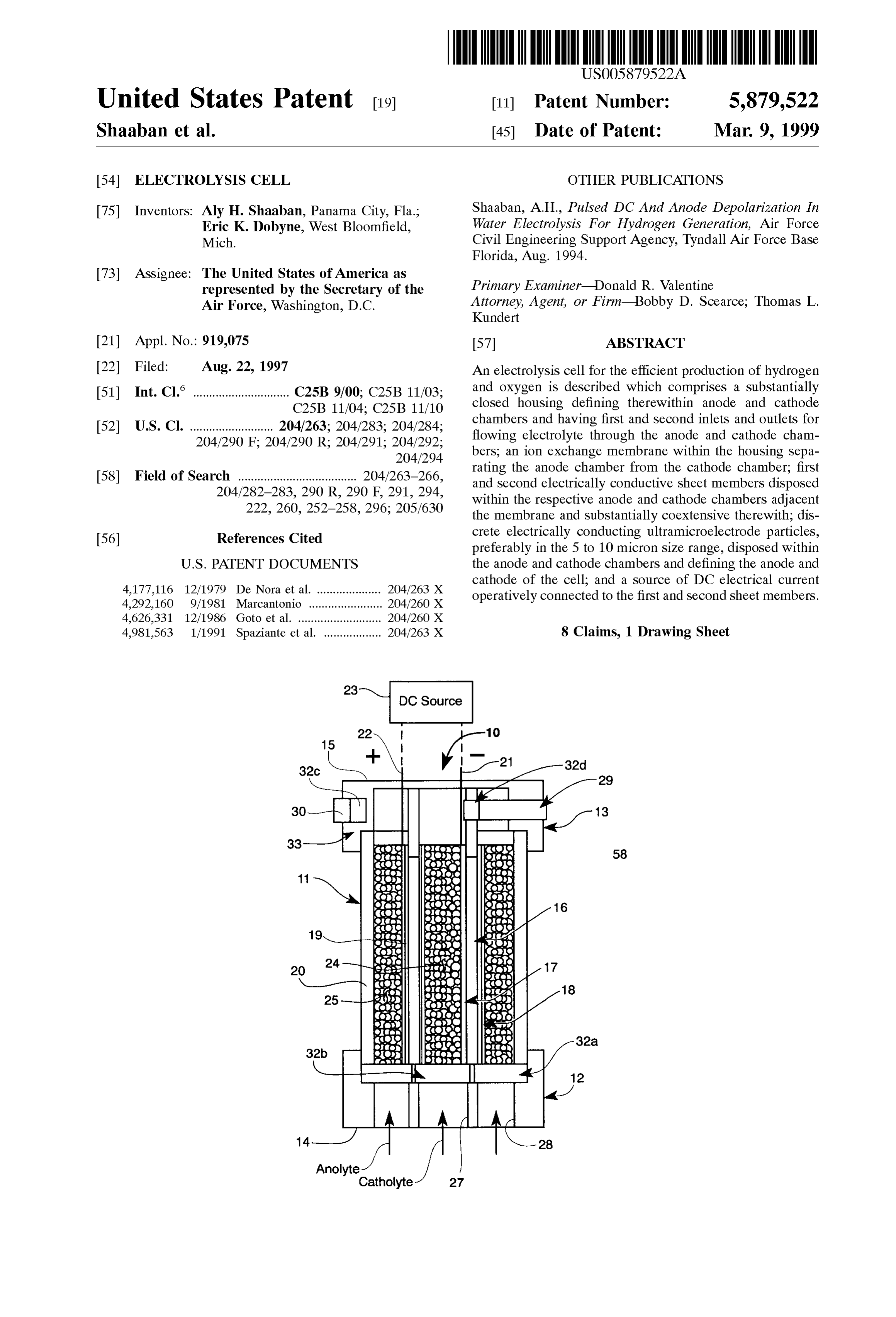
United States Patent (19) 11 Patent Number: 5,879,522 Shaaban et al. (45) Date of Patent: Mar. 9, 1999 54 ELECTROLYSIS CELL OTHER PUBLICATIONS 75 Inventors: Aly H. Shaaban, Panama City, Fla.; Shaaban, A.H., Pulsed DC And Anode Depolarization. In Eric K. Dobyne, West Bloomfield, Water Electrolysis For Hydrogen Generation, Air Force Mich. Civil Engineering Support Agency, Tyndall Air Force Base Florida, Aug. 1994.
73 Assignee: The United States of America as represented by the Secretary of the Primary Examiner Donald R. Valentine Air Force, Washington, D.C. Attorney,y, Ag
Agent, or Firm-Bobbyy D. Scearce; Thomas L.
Kundert 21 Appl. No. 919,075 57 ABSTRACT 22 Filed: Aug. 22, 1997 An electrolysis cell for the efficient production of hydrogen 51) Int. Cl. .............................. C25B 9.00, C25B 11/03 and oxygen is described which comprises a Substantially C25B 11 04: C25B 1110 closed housing defining therewithin anode and cathode 52 U.S. CI 204/263; 204283. 204/284; chambers and having first and Second inlets and outlets for O X O -- O 204290. F. 204/290 R. 2042.91. 2O4,292. flowing electrolyte through the anode and cathode cham s s s 204/294. bers, an ion exchange membrane within the housing Sepa rating the anode chamber from the cathode chamber, first 58) Field of Search42s2 2s3,290R, 29 6 23. and Second electrically conductive sheet members disposed 22. 260 252 35s 296. 205/630 within the respective anode and cathode chambers adjacent s s 4.- O s the membrane and Substantially coextensive there with; dis crete electrically conducting ultramicroelectrode particles, 56) References Cited preferably in the 5 to 10 micron Size range, disposed within
cathode of the cell; and a Source of DC electrical current 32.8 'E R.S." - - - - - - - - - - - - - - - - - - - - 35 operatively connected to the first and Second sheet members. 4,626,331 12/1986 Goto et al... ... 204/260 X 4,981,563 1/1991 Spaziante et al. .................. 204/263 X 8 Claims, 1 Drawing Sheet
Page 2
Drawing sheet — no readable text.
Page 3
ELECTROLYSIS CELL It is another object of the invention to provide an elec RIGHTS OF THE GOVERNMENT trolysis cell containing porous electrodes comprising ultra microelectrode particles.
The invention described herein may be manufactured and It is a further object of the invention to provide an used by or for the Government of the United States for all electrolysis cell providing high current density and high governmental purposes without the payment of any royalty.
reaction rate for the generation of hydrogen.
BACKGROUND OF THE INVENTION
It is another object of the invention to provide an elec
The present invention relates generally to electrolysis trolysis cell for producing hydrogen and oxygen at about cells, and more particularly to a water electrolysis cell for 99.99% purity.
efficient production of hydrogen and oxygen using ultrami These and other objects of the invention will become croelectrodes.
In water electrolysis, a potential is applied between an apparent as a detailed description of representative embodi anode and a cathode immersed in an electrolyte to generate ments proceeds.
hydrogen at the cathode. Rate of hydrogen generation is SUMMARY OF THE INVENTION dependent on the applied current and is independent of 15
Voltage above the minimum potential for electrolysis to In accordance with the foregoing principles and objects of proceed. The limitation on the current is directly related to the invention, an electrolysis cell for the efficient production electrolyte conductivity and electrode Surface area. Conven of hydrogen and oxygen is described which comprises a tional electrolysis cells include Substantially two Substantially closed housing defining there within anode and dimensional plate electrodes. Electrolyte-electrode interface cathode chambers and having first and Second inlets and area is maximized by roughening, perforating or corrugating outlets for flowing electrolyte through the anode and cathode the electrode Surface in order to increase current density and chambers, an ion exchange membrane within the housing lower cell Voltage, but current density has been Substantially limited to about 1000A/m. Porous electrodes having high Separating the anode chamber from the cathode chamber; pore Surface area approximate three-dimensional operation 25 posed within theelectrically first and Second respective conductive sheet members dis anode and cathode chambers and may provide current densities up to 10,000 A/m, but adjacent the membrane and Substantially coextensive there pore size, length and density are not uniform. The pores are with; discrete electrically conducting ultramicroelectrode tortious and closed at the ends which causes gas generated particles, preferably in the 5 to 10 micron size range, inside the pores to be confined by capillary action until the disposed within the anode and cathode chambers and defin gas pressure exceeds the capillary forces. A central core of ing the anode and cathode of the cell; and a Source of DC gas established inside the pore with a thin layer of electrolyte electrical current operatively connected to the first and adhering to the pore walls results in an ohmic drop through Second sheet members.
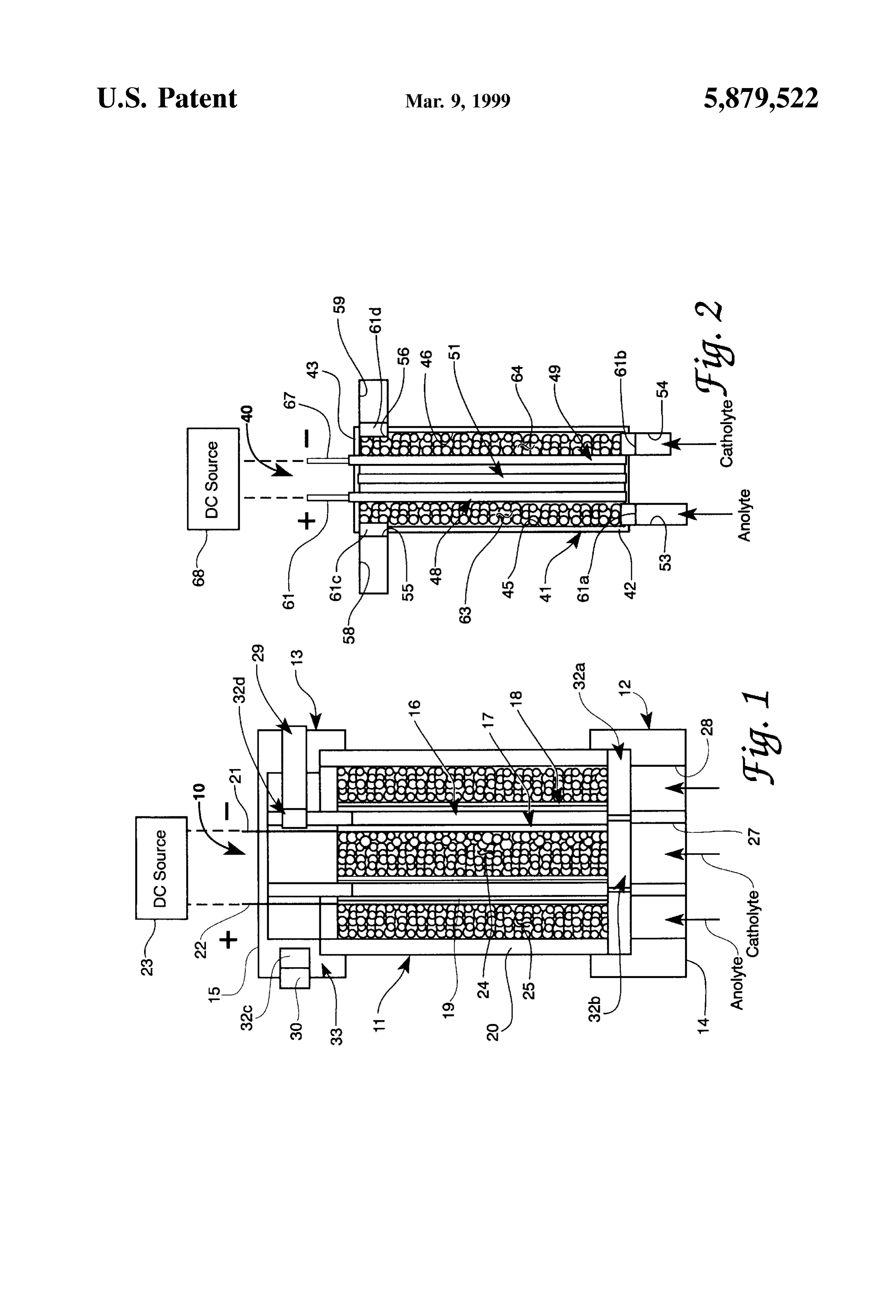
the electrolyte film, which opposes the beneficial effect of increasing electrode Surface area. DESCRIPTION OF THE DRAWINGS The invention Solves or Substantially reduces in critical 35 importance problems with existing electrolysis cells as just The invention will be more clearly understood from the Suggested by providing a monopolar electrolysis cell Struc following detailed description of representative embodi ture in which a membrane Separates the catholyte and ments thereof read in conjunction with the accompanying anolyte chambers and allows only ion eXchange between the drawings wherein:
chambers in order to Separate the generated hydrogen and 40 FIG. 1 shows a Schematic diagram in axial Section of a oxygen, and uses ultramicroelectrode particles with diam cylindrically configured monopolar ultramicroelectrode eters in the micron size range as electrodes in order to electrolysis cell Structured in accordance with the invention; maximize electrode Surface area. The invention can be and operated as a fluidized bed reactor by using electrolyte flow FIG. 2 shows a Schematic diagram in Section of a or by recycling a portion of the generated hydrogen or 45 monopolar ultramicroelectrode electrolysis cell in a slab oxygen to keep the particles in Suspension. The invention configuration Structured in accordance with the invention. may be Statically-fed to avoid electrolyte pumping and circulating. Use of ultramicroelectrodes according to the DETAILED DESCRIPTION invention provides a large Surface area to the flow of Referring now to the drawings, FIG. 1 is a diagram in electrolyte, Small diffusion layer, low ohmic losses, high 50 axial Section of a monopolar ultramicroelectrode electrolysis current densities, and rapid time response with high rate of hydrogen generator cell 10 in cylindrical configuration mass transfer and the associated high operating efficiencies, according to the invention, and FIG. 2 is a Sectional view of as compared to conventional cells containing planar elec a monopolar ultramicroelectrode electrolytic cell 40 in slab trodes. configuration according to the invention. In FIG. 1, cell 10 Background material related to electrolysis generally 55 includes Substantially cylindrically shaped housing 11 hav which may be helpful in understanding the invention may be ing at respective first and Second ends 12,13 end caps 14.15 found by reference to Pulsed DC And Anode Depolarization and having an inner cylindrically shaped membrane 16 In Water Electrolysis For Hydrogen Generation, by A. H. disposed between two concentric Substantially cylindrical Shaaban, ESL-TR-92-55, Air Force Civil Engineering Sup electrode feeders 17.18 defining substantially concentric port Agency, Tyndall Air Force Base FL (August 1994), and 60 cylindrical inner chamber 19 and outer annularly shaped the references cited therein, the entire teachings of which are chamber 20. Housing 11 and end caps 14,15 are constructed incorporated by reference herein. of material such as TEFLON-coated plastic, wood, It is therefore a principal object of the invention to provide aluminum, Steel or other Suitable non-electrically an improved electrolysis cell. conducting material as would occur to the Skilled artisan It is another object of the invention to provide an elec 65 practicing the invention. Membrane 16 Separates oxygen trolysis cell having high current density and operating generated at the anode from hydrogen generated at the efficiency. cathode and prevents short-circuiting of the electrodes. The
Page 4
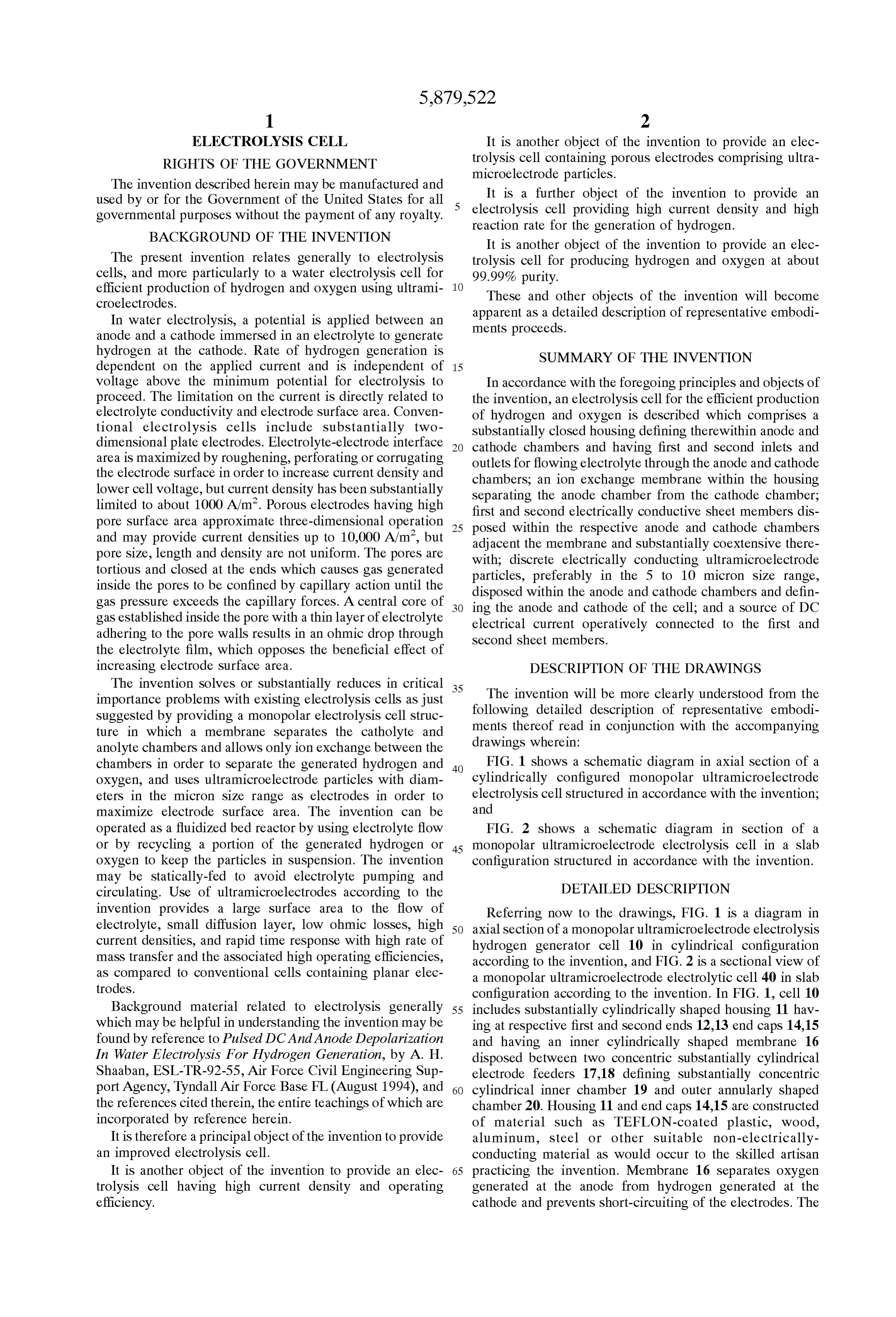
membrane must be compatible with the electrolyte used in thick) bed electrode where material flow and current vectors the cell and, accordingly, comprises a cylindrical layer or are oriented at right angle.
film of asbestos, Suitably coated organic polymers, thermo In each inlet 27.28 and outlet 29.30 porous plugs 32a, b, plastic polymers, or other material known in the art as c, d of appropriate size and shape are disposed in order to appropriate for the Stated purpose. One commercially avail 5 contain particles 24.25 within chambers 19.20 in the event able product that can be used is NAFION-324 manufactured of electrolyte flow surge. Plugs 32a,b,c,d may preferably by DuPont. comprise metal cloth or foam metal. The material used shall Electrode feeders 17.18 (cathode 17, anode 18, in the FIG. be compatible with or Similar to the corresponding electrode 1 embodiment) preferably have roughly the same Surface feeder material. Endcap 15 at second end 13 of housing 11 area, and are disposed respectively internally and externally may be configured to define manifold assembly 33 for of and Substantially concentrically and coextensively with collection of generated hydrogen and oxygen Separately into membrane 16 as suggested in FIG. 1. Electrode feeders Storage containers (not shown).
17.18 are sheet-like members constructed of thin electrically In the monopolar slab configuration for the invention conducting materials. Such as braided metal wires, metal shown in FIG. 2, cell 40 includes a rectangular housing 41 cloth, foam metal or thin metal sheet. The metal used must 15 having first and Second ends 42.43 and comprises Suitable non-electrically-conducting material as Suggested above for be compatible with those used in the cathode and anode housing 11 of cell 10. Container 41 defines a pair of interior particles in chambers 19.20 and preferably be of the same anode and cathode chambers 45,46 Separated by planar material. Cathode terminal 21 and anode terminal 22 are connected respectively to cathode 17 and anode 18 and Inlets 53.54 and outlets 55.56 are defined in membrane electrode feeders 48.49 and ion exchange 51.
extend through endcap 15 for connection to an external DC and Second ends 42,43 of housing 41 to respective first Source 23 of power. Chamber 19 comprises one electrode anolyte and catholyte flow through chambersaccommodate 45,46 and to (cathode) region of cell 10, and chamber 20 comprises the provide outlets 58,59 for drawing oxygen and hydrogen other electrode (anode) region. The anode and cathode from cell 40. Porous plugs 61a,b,c,d disposed at inlets 53.54 regions (chambers 19.20) are fluidized or packed beds and outlets 55.56 serve the same function as plugs 32 of cell containing discrete micrometer sized (preferably about 5 to 25 10 of FIG. 1. Ultramicroelectrode particles 63,64 are dis 10 um) electrically conducting ultramicroelectrode particles posed within chambers 45.46 as suggested in FIG. 2 to 24.25 of titanium, nickel, StainleSS Steel, carbon, metal define the porous electrodes of cell 40. Anode and cathode oxides or metallized glass, including precious metal (e.g., terminals 66.67 are attached to electrode feeders 48.49 and gold, titanium, nickel or platinum) plated glass for maxi extend through housing 41 at end 43 as illustrated for mizing electrode surface area in each of chambers 19.20. connection to a DC Source 68. Materials comprising each Cathode and anode particle materials are Selected to mini element of cell 40 may be the same as correspondingly mize cathode and anode overpotentials. Inlets 27.28 in end named elements of FIG.1. It is noted that more than one cell cap 14 and outlets 29.30 in end cap 15 provide means for (i.e. anode and cathode chambers and membrane flowing anolyte and catholyte from Sources thereof (not combinations) may be included in a single housing to define shown) through chambers 1920. Electrolytes appropriate 35 a multicell Structure.
for use in various embodiments of the invention include It is noted that size of cell 10 or of cell 40 is not diluted Solutions of Sulfuric acid, caustic potash or caustic considered limiting of the invention described herein. How soda, or others known in the electrolysis art. Particle 24.25 ever with reference again specifically to FIG. 2, and for the density is preferably less than the electrolyte density. The purpose of demonstrating the size and capacity of a repre ultramicroelectrode particles are in electrical contact with 40 Sentative cell in demonstration of the invention, a monopolar feeder electrodes 17,18, each particle in the catholyte acting electrolytic cell in the slab configuration denoted by 40 may as a cathode and each particle in the anolyte as an anode. be built with anode and cathode chambers 45,461.5 cm wide Electrodes 17.18 are configured to allow ion transfer but to by 7.5 cm high and 16 cm deep filled to a height of 5 cm with prevent flow of particles into the region containing mem 10 um particles, the cathode chamber 46 containing Stainless brane 16 between electrodes 17,18. Current densities up to 45 Steel particles adjacent a cathode feeder 49 of Stainless Steel 30,000 A/m are achievable. cloth and the anode chamber 45 containing titanium par For operation of the invention in a mode wherein cham ticles adjacent an anode feeder 48 of titanium coated nickel bers 19.20 are fluidized beds, flow of electrolyte is con cloth. This configuration can produce an electrode Surface trolled to keep particles 24.25 in Suspension. For operation area in excess of 500 times that of the effective area of a wherein chambers 19.20 are packed beds, static (or batch) 50 planar electrode with 7.5 cm by 16 cm dimensions. Using electrolytye feed is used, and a portion of the generated 10% sulfuric acid electrolyte pumped with enough velocity hydrogen may be circulated through chamber 19 (catholyte to keep the elctrode particles in Suspension, the cell can chamber) to maintain cathode particles 24 in Suspension and accept current density in the range of 21,000 A/m at a cell a portion of the generated oxygen (or an anode depolarizer potential of 2.5 volts.
in a System where anode depolarization is employed) may be 55 The invention therefore provides a water electrolysis cell circulated through anolyte chamber 20 to maintain anode for efficient production of oxygen and hydrogen using particles 25 in Suspension. ultramicroelectrodes. It is understood that modifications to The packedbed will function as a perfect porous electrode the invention may be made as might occur to one skilled in by increasing the electrolyte-electrode interface area up to the field of the invention, within the scope of the appended about 200 times using 10 um particles and thereby maxi 60 claims. All embodiments contemplated hereunder which mizing the hydrogen yield of the cell. Using particle elec achieve the objects of the invention have therefore not been trodes in Suspension wherein no interaction occurs between shown in complete detail. Other embodiments may be the diffusion layers increases the electrolyte-electrode inter developed without departing from the Spirit of the invention face area to more than 200 times. The fluidized bed is an or from the Scope of the appended claims. excellention Scavenger because of the large Surface area for 65 What is claimed is:
flow of electrolyte if a substantially uniform potential dis 1. An electrolysis cell for the efficient production of tribution is applied Such as by using a thin (about 5 mm hydrogen and OXygen, comprising:
Page 5
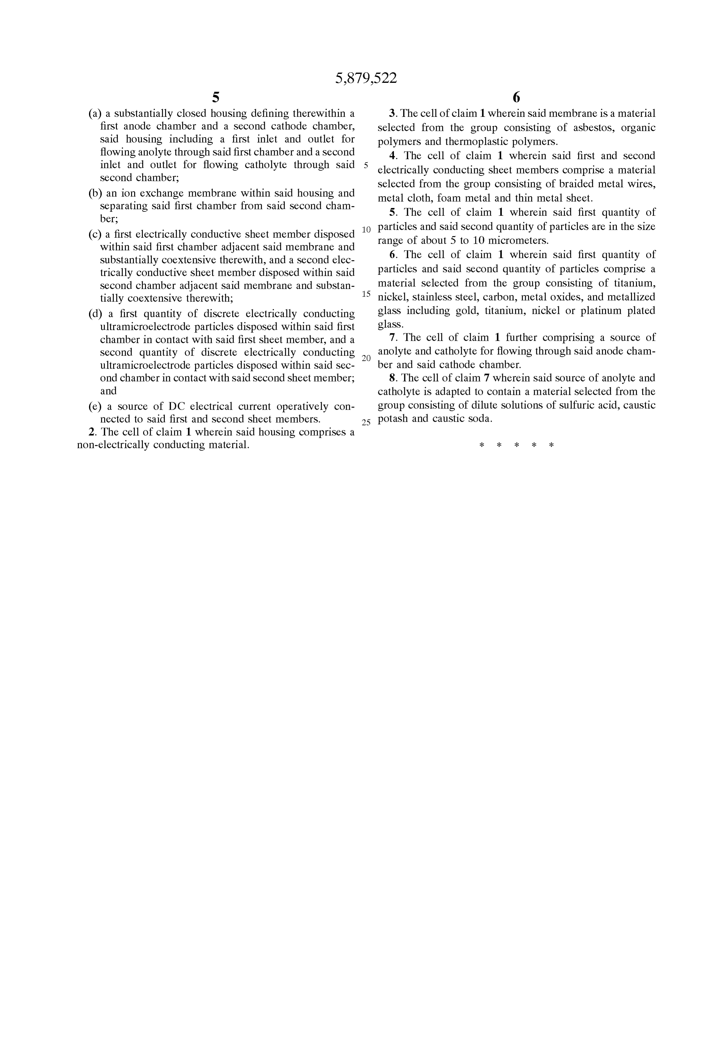
S 6 (a) a Substantially closed housing defining therewithin a 3. The cell of claim 1 wherein said membrane is a material first anode chamber and a Second cathode chamber, Selected from the group consisting of asbestos, organic Said housing including a first inlet and outlet for polymers and thermoplastic polymers. flowing anolyte through Said first chamber and a Second 4. The cell of claim 1 wherein said first and second inlet and outlet for flowing catholyte through Said electrically conducting sheet members comprise a material Second chamber; Selected from the group consisting of braided metal wires, (b) an ion exchange membrane within Said housing and metal cloth, foam metal and thin metal sheet. Separating Said first chamber from Said Second cham 5. The cell of claim 1 wherein said first quantity of ber; particles and Said Second quantity of particles are in the size (c) a first electrically conductive sheet member disposed range of about 5 to 10 micrometers. within Said first chamber adjacent Said membrane and 6. The cell of claim 1 wherein said first quantity of Substantially coextensive therewith, and a Second elec trically conductive sheet member disposed within Said particles and Said Second quantity of particles comprise a Second chamber adjacent Said membrane and Substan 15 material Selected from the group consisting of titanium, tially coextensive therewith; nickel, Stainless Steel, carbon, metal oxides, and metallized (d) a first quantity of discrete electrically conducting glass including gold, titanium, nickel or platinum plated ultramicroelectrode particles disposed within Said first glass.
chamber in contact with Said first sheet member, and a 7. The cell of claim 1 further comprising a source of Second quantity of discrete electrically conducting anolyte and catholyte for flowing through said anode cham ultramicroelectrode particles disposed within Said Sec ber and Said cathode chamber.
ond chamber in contact with Said Second sheet member; 8. The cell of claim 7 wherein said source of anolyte and and catholyte is adapted to contain a material Selected from the (e) a Source of DC electrical current operatively con group consisting of dilute Solutions of Sulfuric acid, caustic nected to Said first and Second sheet members. 25 potash and caustic Soda.
2. The cell of claim 1 wherein Said housing comprises a non-electrically conducting material.
Provenance
- Collection
- Cited prior art
- Original PDF
- patentimages.storage.googleapis.com →
- Filed
- 1997-08-22
- Pages
- 5
- Method
- pdftotext (the PDF's own text layer) + pdftoppm 300dpi page scans
- Source
- Google Patents bibliographic record
- Granted
- 1999-03-09
- Inventors
- Aly H. Shaaban; Eric K. Dobyne; United States Department of the Air Force
- Transcribed from
- patentimages.storage.googleapis.com →