patent · US4726888
Electrolysis of water
23 February 1988
Page 1 — bibliographic record
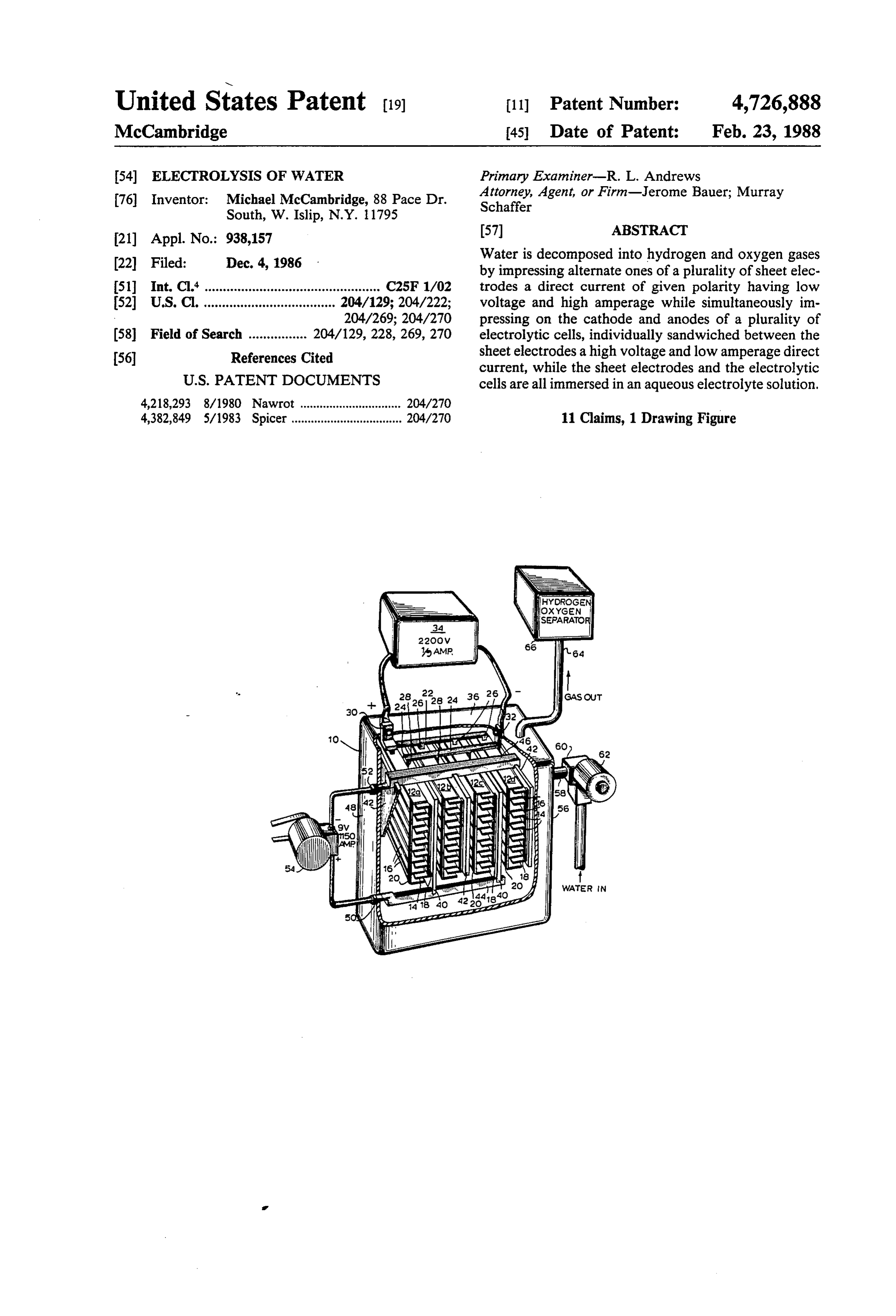
United States Patent (19. 11 Patent Number: 4,726,888 McCambridge 45 Date of Patent: Feb. 23, 1988 54 ELECTROLYSIS OF WATER Primary Examiner-R. L. Andrews 76) Inventor: Michael McCambridge, 88 Pace Dr. Attorney, Agent, or Firm-Jerome Bauer; Murray Schaffer
Water is decomposed into hydrogen and oxygen gases 22 Filed: Dec. 4, 1986 by impressing alternate ones of a plurality of sheet elec 51 Int. Cl." ................................................ C25F1/02 trodes a direct current of given polarity having low 52 U.S. C. .................................... 204/129; 204/222; voltage and high amperage while simultaneously im 204/269; 204/270 pressing on the cathode and anodes of a plurality of (58) Field of Search ................ 204/129, 228, 269, 270 electrolytic cells, individually sandwiched between the sheet electrodes a high voltage and low amperage direct
current, while the sheet electrodes and the electrolytic
4,218,293 8/1980 Nawrot ............................... 204/270 4,382,849 5/1983 Spicer .................................. 204/270 11 Claims, 1 Drawing Figure
Hydrogen
V OXYGeN
SEPARATO
Page 2
Drawing sheet — no readable text.
Page 3
ELECTROLYSIS OF WATER SUMMARY OF THE INVENTION
According to the present invention, a method of
BACKGROUND OF THE INVENTION decomposing water into hydrogen and oxygen gases is The present invention relates to an electrolytic pro provided wherein alternate sheet electrodes are im cess and apparatus for decomposing water and in partic pressed with a direct current of given polarity having ular for the recovery of hydrogen and/or oxygen gases low voltage and high amperage while simultaneously therefrom. impressing on the cathode and anodes of a plurality of Hydrogen and oxygen gases do not exist in nature in electrolytic cells, individually interspersed between the relatively pure form and it is, therefore, necessary to 10 sheet electrodes, a high voltage and low amperage di devise ways for obtaining these gases from the natural rect current, while the sheet electrodes and the electro compositions of which they are a constituent. While lytic cells are all immersed in an aqueous electrolyte many different methods for recovering hydrogen and solution.
oxygen have been devised, the most frequently used 15 The apparatus for decomposing the water into hydro method involves the decomposition of water by elec gen and oxygen gases, in accordance with the present trolysis, since water is relatively abundant and inexpen invention comprises a receptacle for containing the sive, and electricity is generally readily available, al water to be decomposed into which a plurality of sheet though somewhat more expensive. The basic electro electrodes are arranged and spaced in parallel relation lytic process for the separation of hydrogen and oxygen ship to each other. Electrolytic cells, each having at gases comprises the passing of a direct electric current 20 least one cathode and one anode member are sand between an anode and a cathode arranged in dilute wiched between the sheet electrodes in close proximity aqueous solution of an alkali(e.g., sodium chloride) thus therewith. The sheet electrodes are alternately con decomposing the water into its basic constituents. nected to the respective poles of a source of direct cur The generally accepted theoretical voltage for this 25 rent having low voltage and high amperage while the type of electrolysis is 1.23 volts at room temperature. cathode and anode members of the electrolytic cells are However, because of the overloading of hydrogen on connected to the corresponding poles of a source of the electrodes and the internal cell resistance itself, direct current having high voltage and low amperage. voltages of 2.0 to 2.5 or greater are generally required. The apparatus is operated by applying the current si A 15 percent sodium chloride soluticn using iron cath 30 multaneously to the set of electrodes and the sets of odes and nickel plated iron anodes with an asbestos cathode/anodes.
diaphragm separating the electrode compartments op erates at termperatures from 60 to 70 degrees centri tusIndescribed,carrying out the present method with the appara a synergistic effect seems to occur be grade producing low yields of hydrogen, relative to the tween the electrolytic cells having high voltage and low cost of electricity and incidental plant processing costs, 35 amperage by which the electrolysis is chiefly carried Attempts at making the system more efficient by nickel out, caused by the proximity of the adjacent sheet elec plating the anode or by using more exotic noble metals trodes having low voltage and have been tried. However, most of the known cells arrangement seems to increase thehigh amperage. This rapidity at which the produce about 7.0 cubic feett of hydrogen and half as ions are exchanged and the water is decomposed and much oxygen per kilowatt hour. While the gases pro thus provide higher yields of oxygen and hydrogen duced are 99.7 percent pure and are even suitable for hydrogenation of edible oils, the return of only 7 cubic gases It is with greater efficiency.
preferred that the cathode and anode members of feet per kilowatt hour still remains quite costly.
Incidentally, it has been recently proposed to employ each of the electrolytic cells are in the form of rectilin hydrogen gas in the operation of internal combustion 45 ear plates arranged in planes parallel to each other and engines. As a consequence, new attempts have been perpendicular to the sheet electrodes. The anode and made in improving electrolytic cells, so as to reduce not cathode plates alternating in a spaced vertical stack and only costs, but to improve the hydrogen yield. To this being supported in an interconnected manner by com mon conductive rods and buses which connect the re end, reference may be made to U.S. Pat. Nos. 4,608,137, spective anode and cathode rods to the respective poles
the many attempts to improve electrolytic cell con the source of current.
struction and the method for decomposing water and The receptacle is provided with means for feeding even the use of exotic materials, the efficiency of such water to it, to maintain a selective level of water in cells have not been greatly improved over the basic which the sheet electrodes and cathode and anode parameters known for some time. 55 plates are immersed. Suitable controls are provided for It is an object of the present invention to provide an automatically maintaining the level in response to the improved process for the decomposition of water into utilization or decomposition of the water and/or the hydrogen and oxygen gases which has greater effi production of the gases. Preferably the receptacle is a ciency and employs less power than heretofore known. hermetically enclosed tank and is provided with duct It is another object of the present invention to pro means for withdrawing the gases therefrom and conduit vide a continuous process for producing hydrogen and means for feeding the water thereto, all of which sea oxygen gas in an electrolytic cell which overcomes the lingly pass through the walls of the tank. disadvantages and inherent difficulties of the known Full details of the present invention are set forth in devices. It is yet another object of the present invention the following description and are illustrated in the ac to provide a electrolytic cell which is simple, non-cor 65 companying drawings.
rosive and durable.
These objects together with other objects and advan BRIEF DESCRIPTION OF THE DRAWINGS tages will be apparent from the following description. In the drawings:
Page 4
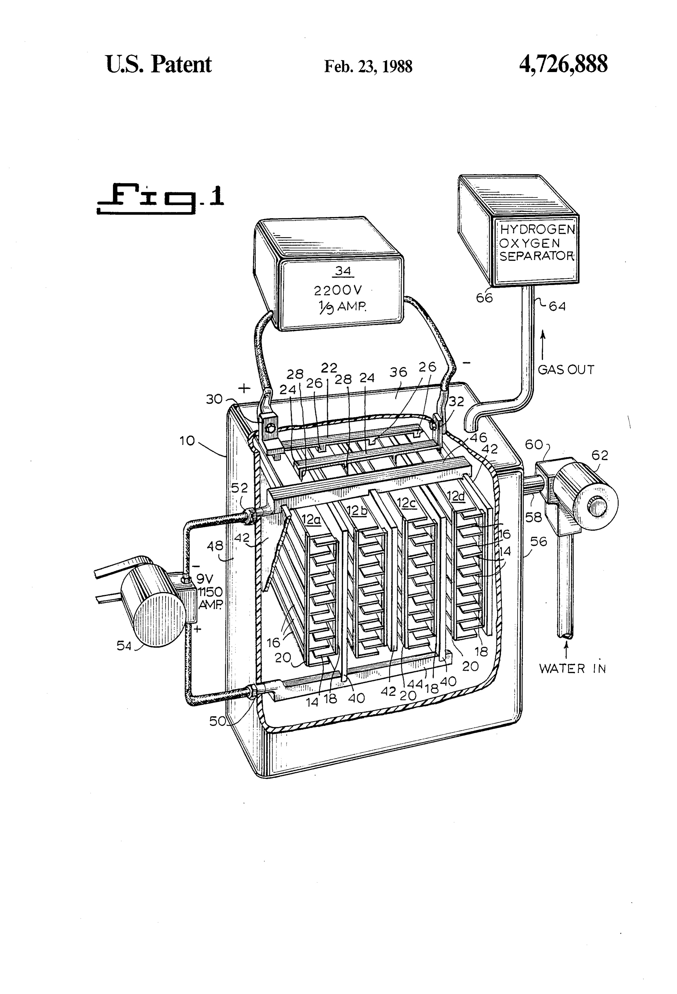
FIG. 1 is a schematic diagram of an electrolytic cell constitute anode electrodes, are welded or fixedly fas illustrating both the apparatus and the process of the tened to a common low-voltage bus 44 while the sheets present invention. 42 which constitute the cathccle electrodes are con
DESCRIPTION OF THE INVENTION
nected likewise to a common low-voltage bus 46. The 5 buses 44 and 46 extend in the horizontal direction out
The broad concepts of the present invention can best wardly of the side wall 48 of the tank 10 being rigidly be understood by considering an exemplary form of secured in the wall 48 so as to support the plates 40 and apparatus for the decomposition of water. As seen in the 42. Supplementary supporting brackets may be used, if drawing, the exemplary apparatus comprises an inert, desired. Each of the buses 44 and 46 are connected to a preferably high density plastic hermetically enclosed 10 conductor bracket 50 and 52 respectively which are and sealed tank 10. Arranged within the tank 10 are a connected to a source 54 of low voltage/high amperage plurality of electrolytic cells 12a-d, each formed of a current, with the polarities as indicated. stack of alternating horizontally disposed high voltage Extending through the opposite wall 56 of the tank 10 anode plates 14 and cathode plates 16. In the drawings, is an inlet duct 58 which is connected via a flow control four such electrolytic sets are illustrated, although the 15 valve 60 and a pump 62 to a source of water. Both the number is not at all critical. Similarly, the number of flow control valve 60 and the pump 62 are conven anode plates 14 and cathode plates 16 are not critical tional, the valve being preferably remotely controlled although they are preferably arranged in pairs. as by the use of solenoid controls, so that water flow The individual high voltage anode plates 14 and cath can be selectively regulated to insure a constant uniform ode plates 16 are approximately 10 inches long, two 20 throughput and operation of the electrolytic cell. Suit inches wide and one and one-half inches thick and are able controls regulating the level of water, in response horizontally spaced from each other by about 3/16ths to the gas output, can be provided. Extending out of the of an inch. The anode plates 14 and the cathode plates top wall 36 is an air duct 64 through which the gases 16 in each set are held together by vertically disposed produced in the tank 10 under the electrolytic process supports 18 and 20, respectively, adjacent the forward 25 can be withdrawn. The duct 64 leads to a hydrogen and rear ends of the plates. The supports 18 and 20 are voxygen separator 66 of known construction so that the preferably flat, although round rods may be used but gases may be separated and separately contained and should have such strength and rigidity as to be able to stored.
support the plates in the disposition described. The Preferably, the source of water, not shown, is pre supports or rods 18 and 20 are of a highly conductive 30 mixed with a selected electrolyte, so that the water metal, so as to, in effect, not only support the plates, but solution initially supplied to the tank 10 has the desired also be a conductor bus for them. concentration of the electrolyte. As an alternative, a Extending across the top of the grouped cells 12a-d separate source of the electrolyte can be provided and are a pair of high voltage bus bars 22 and 24, respec separately introduced into the water pump, water con tively. Bus bar 22 is formed with short depending legs 35 duit or directly into the tank. The tank 10 is provided 26 which are welded or otherwise fixedly fastened to with water level indicators, temperature gauges, pres the topmost cathode plate in each of the cells 12a-d. sure gauges and the like, as would be well known to The bus bar 24 while similarly formed, has slightly those skilled in this art which operate to regulate the longer depending legs 28 which are welded or fixedly subsequent feeding of water to maintain the acid con fastened to a vertical support rod 18 of each cell 12a-d centration at the desired level. Because during decom although, if desired, the legs 28 may be similarly welded position the conversion of the water to gas results in or fastened directly to the topmost anode plate in each increased concentration of the electrolyte, the subse cell. Each of the high voltage bus bars 22 and 24 are quent feeding of water can be generally made without welded or bolted to a highly conductive metal angle added electrolyte.
bracket 30 and 32, respectively, each serving as a con 45 In accordance with the present invention, all of the ductor pole for connection to a source 34 of high vol high voltage anode/cathode plates 14 and 16, as well as tage/low amperage current. The brackets 30 and 32 are the low voltage electrodes 40 and 42 are formed of a set within the top wall 36 of the tank 10 by known ferrous metal base, coated with a layer of platinum, the conventional means so that they are securely fixed and depth of thickness of which is not critical. The source of are able to support the grouped electrolytic cells 12a-d 50 current 32 for the high voltage plates is preferably a freely depending from their associated buses 22 and 24. transformer having an output of 2,200 volts and 1/9 Because of the size of the plates, bus bars, supporting amp current (the commercially available transformer rods, etc. the cathode/anode cells are maintained in employed to operate household oil burner systems is fixed, spaced disposition, as described relative to each such a transformer). The low voltage source is prefera other without the need for further supporting means, 55 bly a 23 to 30 hp generator producing 9 volts and 1.50 although such supporting means may be used if they are amps (e.g. automobile generator). The electrolyte is also desired. sulfuric acid which when mixed with water provides a The electrolytic cells 12a-dare sandwiched between solution in the range of a 2 to 20 percent aqueous con vertical low voltage sheets 40 and 42 of alternate polar centration, although concentration of 10-15 is pre ity. The vertical sheets 40 and 42 are about 10 inches 60 ferred.
long and have a height coextensive with that of each of Prior to operating the electrolytic cell, the electrolyte the electrolytic cells 12a-d and a thickness slightly solution is introduced into the tank 10 until all of the thicker than the individual anode or cathode plates 14 plates are fully immersed. Once the system is filled and and 16. The vertical low voltage sheets 40 and 42 are electric current supplied to the respective plates, the positioned between and straddle the adjacent electro 65 electrolytic process is initiated and continues on with lytic cells 12a-d so as to be as close to the edges of the out hindrance, so that a continuous decomposition of high voltage anode plates 14 and cathode plates 16 as is the water results and gases are produced which are possible without contacting them. The sheets 40, which ducted outwardly through the duct 58. During subse
Page 5
quent electrolysis, water and electrolyte to maintain the of said electrolytic cells being connected to the corre desired concentration is continuously added to maintain sponding poles of a source of direct current having high the water level and the electrolyte solution at the prede voltage and low amperage, and means for withdrawing termined concentration. Since the electrolysis result in the hydrogen and oxygen gases upon decomposition of the depletion of the water/electrolyte solution, the con 5 the water.
centration of electrolyte increases as the process pro 2. The apparatus according to claim 1 wherein said ceeds. Therefore, only water need be continuously fed cathode and anode members of said electrolytic cells to insure proper level in the tank. Additional electrolyte are rectilinear-shaped plates arranged in planes substan may be added periodically and/or only when needed. tially parallel to each other and substantially perpendic It is believed that the high voltage plates 14 and 16, 10 ular to said sheet electrodes.
forming the electrolytic cells 12a-dactually provide the 3. The apparatus according to claim 2 wherein the major electrolysis while the low voltage electrodes 40 plates forming the anode and cathode members of each and 42 act to reduce the resistance of the electrolyte to electrolytic cell are alternately arranged in a spaced the high voltage/low amperage current. This combina vertical stack, said cathodes being supported in said tion unexpectedly enhances the level and speed of the 15 stack by a first common conductive rod and said anodes electrolysis and as a result large yields of gases are pro being supported in said stack by a second common vided at lower power cost input. The combination of conductive rod, the rods in each electrolytic cell being the high voltage/low amperage plates arranged perpen connected to a respective common anode and cathode dicularly to the low voltage/high amperage electrodes bus.
in a box-like formation is deemed to provide a synergis 20 4. The apparatus according to claim 1 including tic effect, particuarly where the high voltage, but low means for feeding water to said receptacle to maintain a current is applied to the small but significantly more selected level of electrolyte therein. numerous anode/cathode plates 14 and 16. The arrange 5. The apparatus according to claim 4 including ment of this relatively small high voltage plates, parallel means for maintaining a selected level of electrolyte to each other, provides an extremely large surface area 25 concentration within said water. for transfer of ions between anode and cathode and for 6. The apparatus according to claim 1 wherein said the carrying out of the electrolytic process. receptacle is a hermetically sealed and enclosed tank Further, because of the high yield relative to time, the provided with duct means for withdrawing gas there high concentration of sulfuric acid of anywhere from 10 from and conduit means for supplying water thereto. to 20 percent enables a large conversion of water in the 30 7. The apparatus according to claim 1 wherein the throughput process, without fouling the electrolytic means for supplying direct current to said sheet elec system or causing corrosion. trodes comprises a low voltage generator in the range Lastly, the use of platinum coating for the plates, of 9 volts and 1150 amps. and the means for supplying while presumably considered to be a high cost factor, is the direct current to said cathode and anode plate com believed to eventually result in lower costs, since even 35 prises a transformer within a range of 2200 volts and 1/9 though numerous plates and sulfuric acid electrolyte amps.
solution are used, the platinum inhibits corrosion so that 8. The method of decomposing water into hydrogen they do not have to be readily replaced as would the and oxygen gases comprising the step of impressing obviously cheaper and conventional plates. upon alternate ones of a plurality of sheet electrodes a Various structural and procedural embodiments have direct current of given polarity having low voltage and been described. Various changes, modifications and high amperage and impressing upon the cathodes and other embodiments will be apparent to those skilled in anodes of a set of elecrolytic cells interposed between the art. It is accordingly intended that the present dis said sheet electrodes a high voltage and low amperage closure be taken as illustrative only of the invention and direct current, while said sheet electrodes and said elec not limiting of its scope. 45 trode cells are immersed in an aqueous electrolyte solu What is claimed is: tion, and withdrawing said hydrogen and oxygen gases 1. Apparatus for decomposing water into hydrogen from contact with said water.
and oxygen gases comprising a receptacle for contain 9. The method according to claim 8 wherein the ing water to be decomposed, a plurality of first sheet electrolyte solution comprises a 2 to 20 percent concen electrodes arranged and spaced substantially in parallel 50 tration of sulfuric acid in water. - relationship to each other within said receptacle and a 10. The method according to claim 9 wherein said plurality of second sheet electrodes defining a plurality electrolyte solution comprises a 10 to 15 percent con of sets of electrolytic cells each set having at least one centration of sulfuric acid in water. cathode and one anode member, interposed between a 11. The method according to claim 9 wherein the pair of said sheet electrodes, said first sheet electrodes 55 cathode and anode of said electrolytic cells are pro being alternately connected to the respective poles of a vided with 2200 volts and 1/9 amps and the sheet elec source of direct current having low voltage and high trodes are provided with 9 volts and 1150 amps. amperage and the cathode and anode members of each k is
Provenance
- Collection
- Cited prior art
- Original PDF
- patentimages.storage.googleapis.com →
- Filed
- 1986-12-04
- Pages
- 5
- Method
- pdftotext (the PDF's own text layer) + pdftoppm 300dpi page scans
- Source
- Google Patents bibliographic record
- Granted
- 1988-02-23
- Inventors
- Michael McCambridge
- Transcribed from
- patentimages.storage.googleapis.com →