patent · US4463063
Hydrogen generator
31 July 1984
Page 1 — bibliographic record
United States Patent (19) 11 Patent Number: 4,463,063 Adhart 45) Date of Patent: Jul. 31, 1984 54 HYDROGEN GENERATOR 4,254,190 3/1981 Zaromb ............................ 429/17 X 75 Inventor: Otto J. Adlhart, Newark, N.J. Primary Examiner-Charles F. LeFevour 73) Assignee: Engelhard Corporation, Iselin, N.J. . 57 ABSTRACT (21 Appl. No.: 399,057 This disclosure relates to a replaceable cartridge hydro gen generator of the type which relies at least partially (22 Filed: Jul. 16, 1982 on the process of anodic corrosion to produce hydro (51) Int. Cli.............................................. H01M 8/18 gen. The cartridge has an outer container wall which 52 U.S. Cl. ......................................... 429/19, 429/94 holds a consumable anodic material and an electrolyte 58 Field of Search ................... 429/19, 118,119, 17, therein. The container wall can be made the cathode of 429/94 the cell. An electrical circuit is provided with a switch means between the anode and cathode to regulate cur (56) References Cited rent flow and hydrogen is generated when there is cur
2,850,557 9/1958 Kirk et a 429/167 X instantaneously controlled by the switch means. The 3,928,075 12/1975 Bass ............ ... 429/119 container and anodic material can be cylindrically 3,981,747 9/1976 Doniat et al. ... , 429/15 shaped and placed in an upright position when in use to 4,175,165 11/1979 Adlhart ................................. 429/30 have the electrolyte cover the anodic material. 4,198,475 4/1980 Zaromb ...... ... 429/19 X 4,218,520 8/1980 Zaromb ................................. 429/15 20 Claims, 4 Drawing Figures
HYDROGEN
GENERATOR
Page 2
Drawing sheet — no readable text.
Page 3
Drawing sheet — no readable text.
Page 4
Drawing sheet — no readable text.
Page 5
It is an object of the invention to provide a demand
HYDROGEN GENERATOR responsive hydrogen generator.
It is a further object of the invention to provide a
BACKGROUND OF THE INVENTION hydrogen generator which can be turned on and off This invention relates to hydrogen generators, and substantially
It is a further object of the invention to provide a more particularly, to a cartridge-type hydrogen genera hydrogen generator which has a high energy density tor which relies at least partially on the process of an and improves the rate of hydrogen formation relative to odic corrosion to produce hydrogen. . . . .
Hydrogen generators which produce quantities of 10 theItamount of materials employed. is a further object of the invention to provide a hydrogen of relatively high purity have many uses. One replaceable cartridge-type hydrogen generator. such use is to provide hydrogen fuel to a fuel cell power generation system. Fuel cell systems, especially those compact hydrogenobject
It is a further of the invention to provide a generator relative to the amount and used in remote locations, are equipped with integral fuel rate of hydrogen generated thereby. sources to operate the cell over a period of time. One 15 approach for supplying hydrogen to the cell is by hav ing a hydrogen generator located at the fuel cell to .
SUMMARY OF THE INVENTION
The invention relates to a cartridge-type hydrogen supply the needs of the cell. Such hydrogen generators generator which relies at least partially on the process are desirably demand responsive; that is, they produce of anodic corrosion to produce hydrogen only when the fuel cell needs it. Demand 20 sumable anodic material and a cathodichydrogen having a con material which responsive generators should be designed to require - are at least partially immersed in an electrolyte. little or no hydrogen storage after the hydrogen is gen operation of the generator is controlled by switchingThe an erated and before it is supplied to the fuel cell. This is . electrical line which controls the current flow between beneficial from the safety standpoint.
One type of known hydrogen generator uses a gas 25"...theInanode and cathode. . . . . . a preferred embodiment of the invention, the an generator cartridge. Hydrogen is produced by the reac odic and cathodic materials form parts of the replace tion of water and a solid cartridge charge, such as a able cartridge. The cartridge has a container which calcium hydride which reacts vigorously with water, to supports the anodic material therein and holds the elec generate hydrogen gas and leave a solid residue in the form of a metal hydroxide. Hydrogen generators em 30 trolyte. The container can serve as the cathode and ploying cartridges of this type normally employ a reser nected toelectrical have an line joined thereto which is con the anode after passing through a switch voir of water or provide a chamber into which wateris means. The switch means, when allowing current to supplied and brought into contact with the cartridge flow in the line, enables the generator to produce hy charge. When it is desired to generate hydrogen, one or 35 drogen and, when preventing current from flowing, more cartridges are placed in a reaction tank and then disables the generator from producing hydrogen. In a water is supplied to the reaction tank. As the water level further preferred embodiment of the invention, the rises, it comes into contact with and covers the car. anodic material is magnesium, aluminum, or a magne tridge. A liner in the cartridge becomes saturated with sium or aluminum alloy, and the container material is water and the water passes therethrough and into steel. The anodic material has a shape which emphasizes contact with the cartridge's charge. The water reacts its surface area relative to its volume. The cathodic exothermically with the particles to form calcium hy material is configured to be located closely adjacent to droxide and hydrogen gas. as much of the surface area of the anodic material as In demand responsive hydrogen generators, there are practical. .
several aspects of the hydrogen generation system 45 In a still further preferred embodiment, the container which are of importance. The first is the ability to pre is in the shape of a cylinder, the anodic material is sub cisely control the hydrogen formation process; that is, stantially coaxially located therein and a steel sheet or the ability to start the process and stop the process mesh material is substantially coaxially located therein substantially instantaneously. The generator, desirably, around and closely adjacent the anodic material. The should not have a lag factor in providing hydrogen to 50 anodic material cylinder is long relative to its diameter the system that utilizes it, such as a fuel cell, which to form a large surface area to interact with the closely could jeopardize the continuous operation of the sys adjacent steel mesh. The cartridge can be arranged in tem. Similarly, the generator, desirably, should not have any position as long as the anode is at least partially a lag factor in stopping the formation of hydrogen after covered by the electrolyte. An upright position is pre the requirements of the system to which it is fed have 55 ferred.
been satisfied since the excess hydrogen would have to BRIEF DESCRIPTION OF THE DRAWINGS be bled off or placed in some sort of storage facility,
Having to bleed off excess hydrogen would, of course, The invention is described with respect to specific waste a portion of the hydrogen produced and make the embodiments thereof which are illustrated in the fol generator somewhat inefficient. A second important 60 lowing drawings wherein:
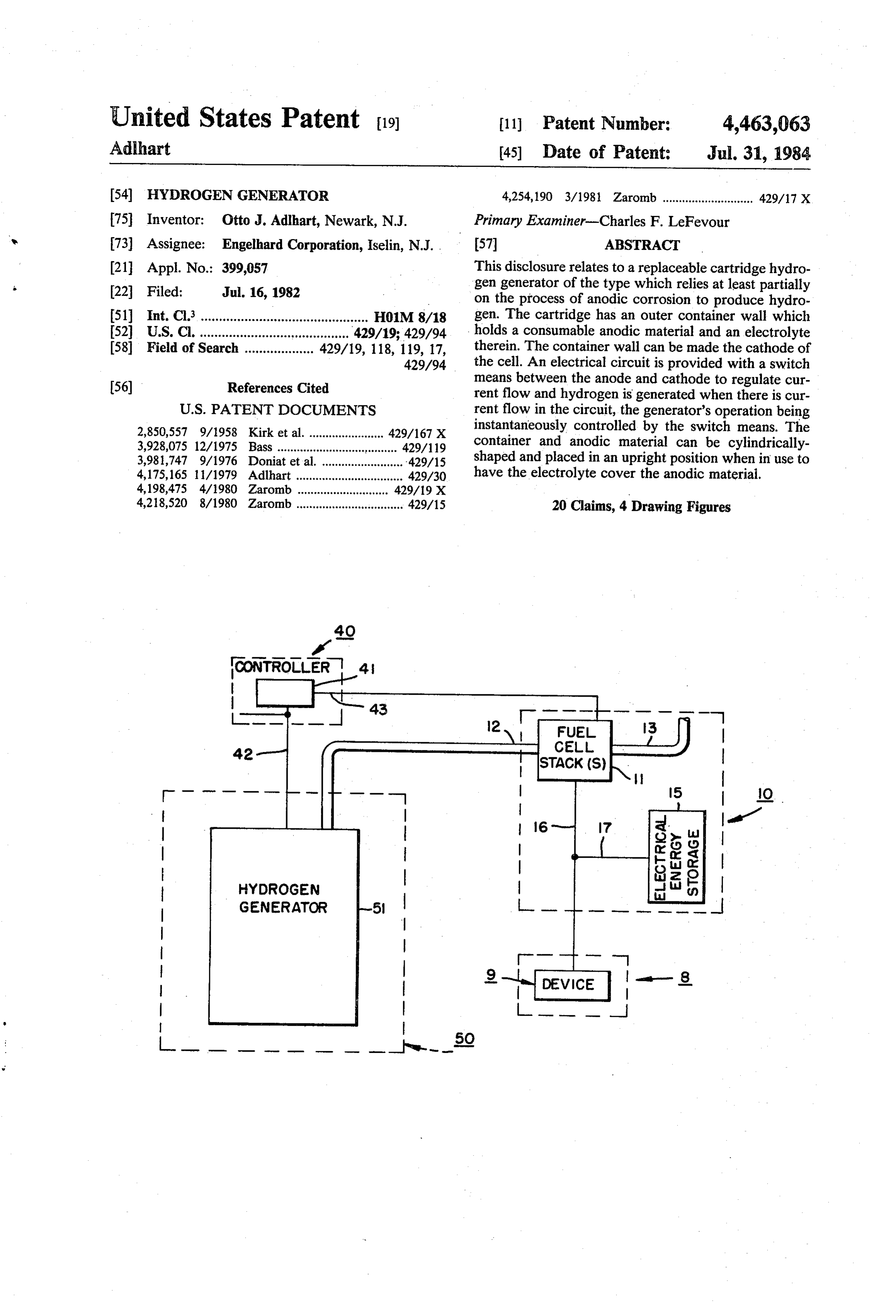
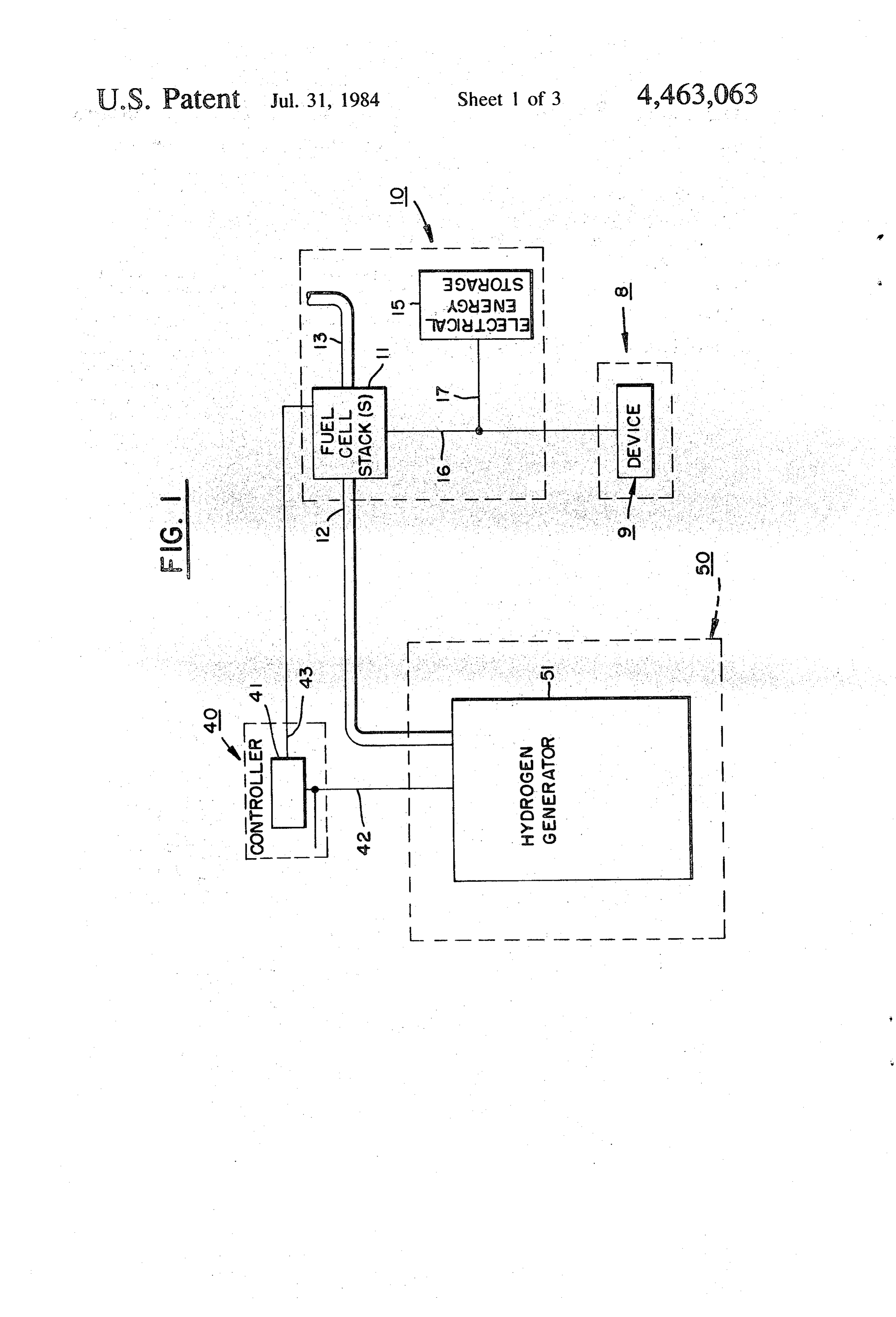
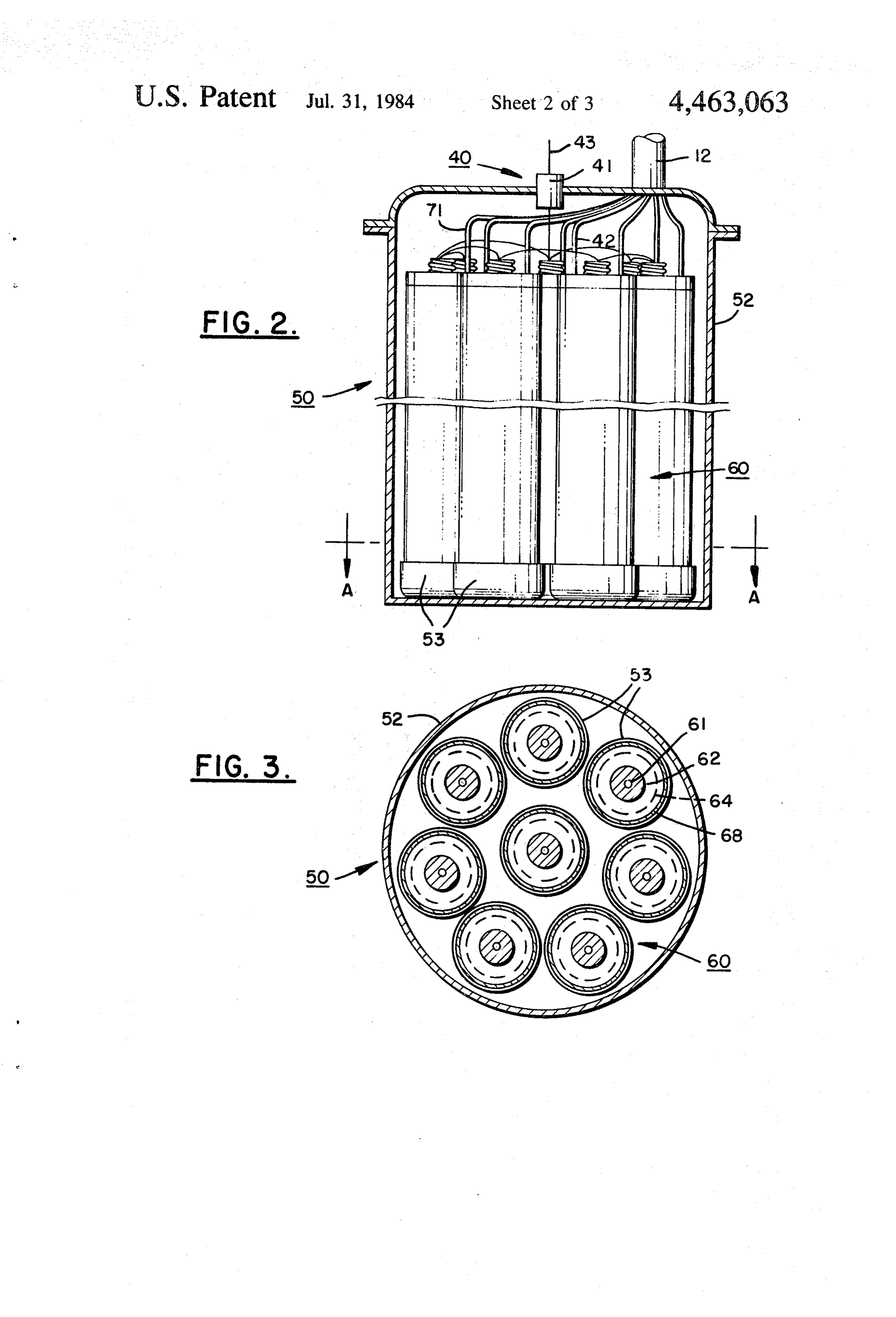
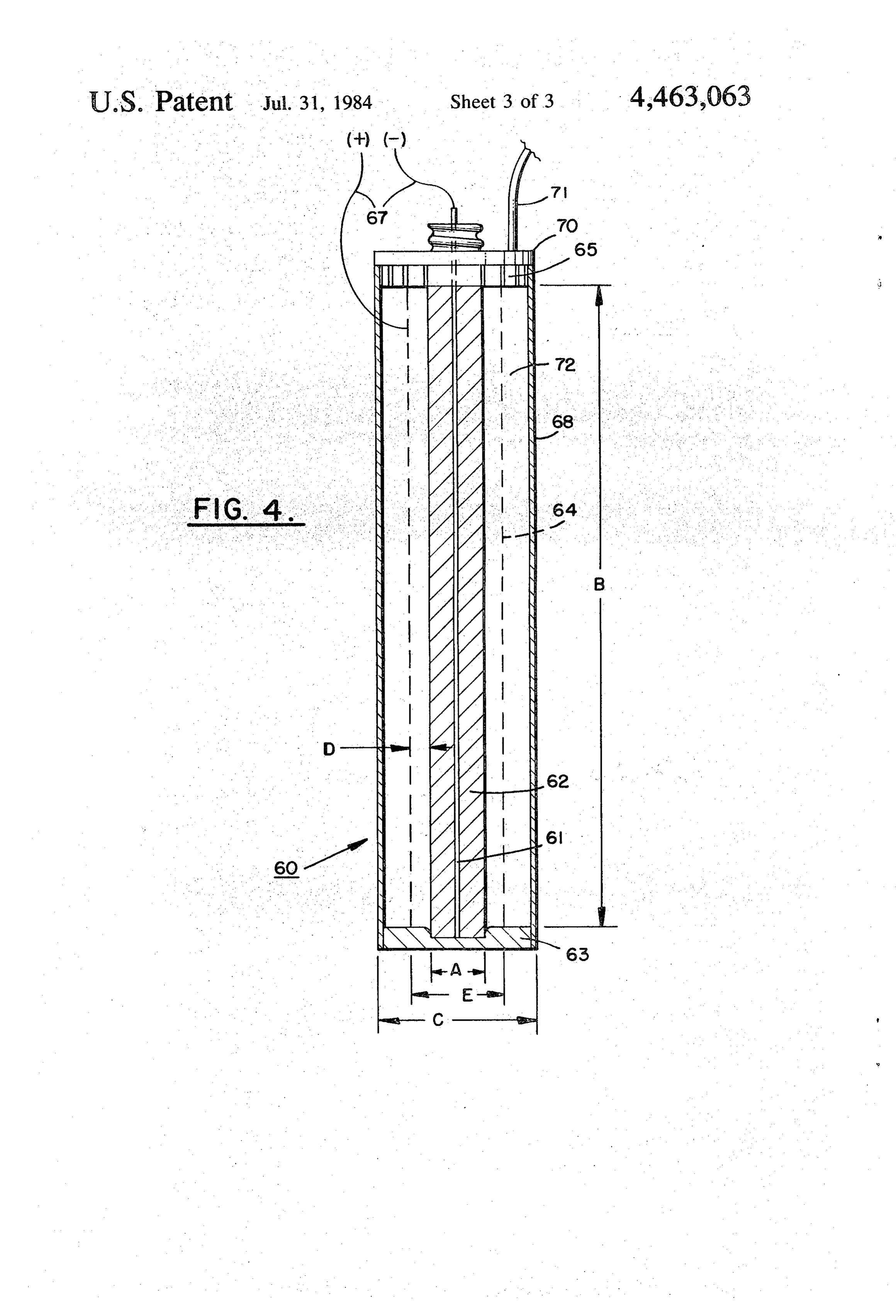
consideration is the rate of hydrogen production during FIG. 1 is a schematic illustration of the hydrogen the generator's operation. The formation of hydrogen generator within a fuel cell system. should be at a sufficiently high rate for the application FIG. 2 is a schematic illustration of a plurality of intended. It is also desirable to have the generator em. cartridge-type hydrogen generators within a drun. ploy an anodic material of high energy density, to have 65 FIG. 3 is a view of the apparatus in FIG. 2 taker. a high output of hydrogen for the volume and weight of through section A-A. w the cartridge and a high degree of utilization of the FIG. 4 is a schematic illustration of one embodimeni reactants. of the cartridge.
Page 6
OETAILED DESCRIPTION OF THE such as a surge battery, to carry the load requirements INVENTION through periods of operational bursts.
In this embodiment, controller 40 enables hydrogen
Referring more particularly to the drawings, wherein generator 50 to be regulated directly by the hydrogen like reference numerals are used throughout to desig requirements of the stack. The hydrogen generator is nate like elements, FIG. 1 schematically illustrates one turned on and off and regulated by controller 40. Con embodiment of a system using the hydrogen generator. troller 40 can be any suitable device that operates in the The hydrogen generator disclosed herein can be used manner intended. For instance, it can be a switch means, for any suitable purpose where there, is a requirement or relay 4, that is able to monitor, through line 43, the for hydrogen. It can be a free-standing apparatus, to O electrical energy output of a control cell (not shown) tally unattached and unintegrated into a larger system, within the stack. Alternatively, it can be a rheostat to used simply to generate hydrogen for any purpose vary the hydrogen generation as a function of the cur whatsoever. It can also be a part of a larger system rent flow. The level of output from the control cell can having a specific need for hydrogen. Purely for the control the switch that turns the generator on and off. purposes of convenience of description, the hydrogen 15 Any other suitable means can be used to automati generator is disclosed in association with a fuel cell cally have controller 40 call for more hydrogen from herein. It should be understood, however, that its use is generator 51 when the fuel cell stack needs it. For in not restricted to this application. stance, a signal representing the pressure of the hydro The fuel cell system shown in FIG. 1 includes four gen within the consuming device or the temperature of major sub-systems sectioned-off in dotted-line boxes; 20 the consuming device itself could be fed to a suitable, energy cell 10, load 8, controller 40 and hydrogen gen conventional control device within controller 40 to erator 50. Energy cell 10 has at least one fuel cell and is close and open the switch means to enable and disable, depicted here as having a plurality of individual fuel respectively, the operation of generator 51. In addition, cells arranged in one or more stacks. The term "fuel cell a simple manually-operated switch or rheostat could be stack” means an arrangement whereby more than one 25 placed in controller 40 particularly in those instances individual cell is placed back-to-back in a stack fashion. wherein the hydrogen generator is a stand-alone appa Each cell can include a catalytic fuel electrode, to ratus for the generation of hydrogen for any use. which hydrogen is fed, a catalytic oxidant electrode, to The configuration of generator 50 and the manner by which air is fed, and an electrolyte member therebe which it forms hydrogen is discussed below in reference tween. The system requires no moving parts since air is 30 to FIGS. 2-4. The hydrogen produced by generator 50 supplied by diffusion and water created by the cells is in the system shown in FIG. 1 is fed from the generator vaporized and drained from the cell stack by wicking. 50 to fuel cell stack 11 through pipe line 12. In the case Hydrogen is supplied to the fuel cells by the hydrogen wherein hydrogen generator 50 is a stand-alone system, generator. Individual fuel cells can be of any suitable the hydrogen can be stored in any suitable container type, for instance, they can contain an electrolyte of a 35 (now shown) connected to generator 50 by any suitable solid polymer type and the stack construction can be of pipe line similar to line 12.
the bi-polar type as disclosed in U.S. Pat. No. 4,175,165. Attention is now drawn to FIGS. 2-4 which illustrate The stack has a means for receiving a supply of hy the cartridges used in hydrogen generator 50. The gen drogen, line 12, and a means for removing excess fuel, erator, in this embodiment, has a cartridge holding bleed line 13. The bleed line is only a precautionary means, drum 52, with a plurality of cartridges 60 lo measure in the present system. Since the hydrogen gen cated therein. The drum, when used with a system such erator is a demand responsive one, it is unlikely that as that depicted in FIG. 1, may be permanently attached much excess or waste hydrogen would be created. The to the fuel cell system main frame (not shown). The fuel cell stack is connected to controller 40 by electrical drum may have therein a means for locating and mount line 43 and is also connected to load 8 by electrical line 45 ing cartridges 60 such as locators 53. The locators can 16. The purpose of controller 40 is to turn the hydrogen be made of any suitable material such as an electrically generator on and off, and to regulate the rate of hydro insulating material. In this embodiment, the interior gen generation. Although non-essential, energy cell 10 bottom surface of the drum contains a plurality of car may also have an electrical energy storage means 15 tridge locators 53 which facilitate the insertion of car which is connected to electrical line 16 between the 50 tridges 60 in the drum by providing a slightly larger stack and the load. opening than the periphery of the cartridges into which The purpose of stack 11 is to generate electrical en the cartridges can be inserted. The drum also provides ergy or power to be used by load 9. The load, here electrical separation for the plurality of cartridges. depicted simply as containing device 9, can be any type Each cartridge in the drum has a pipe means, such as of load requiring electrical energy to operate. One par 55 hose 71, or merely an opening, which is adapted to ticular use for the presently described fuel cell system is allow the hydrogen produced by the cartridge to be fed as a power source for an ocean weather buoy which is to the fuel cell stack through feed line 12. Controller 40 placed in remote regions and is expected to be deployed is shown, in this embodiment, mounted to the drum and in service for long periods of time. The devices of the the cartridges and controller are shown as being electri buoy commonly needing a source of electrical energy 60 cally wired, in series fashion, by electrical wires 42. The are those that collect, store and transmit weather data to cartridges are wired to each other and across the switch satellites, ground stations, or ships. Fuel cell systems are means, or relay, of controller 40 so that one continuous ideal for this purpose since they can be made compact, electrical circuit is made between the cartridges and reliable, and self-regulating. Since such buoys do a vari switch. When the switch is open, no current is possible ety of tasks, load requirements change over a period of 65 through this circuit. However, when the switch is time for the fuel cell stack. It is because of the varying closed, current flows through the circuit. load profile over a period of operation that it may be Basically, the cartridge contains a consumable anodic desirable to include electrical energy storage means 15, material, a cathodic material, an aqueous electrolyte
Page 7
therebetween and a means to complete the circuit be nated and container 68, if made of a suitable cathode tween the anodic and cathodic materials when hydro material, can become the cathode. In this case, line 67 gen is to be generated, thereby enabling electrical cur would be connected to the container wall instead of the rent to flow through the electrolyte between the anodic steel mesh material. In a further embodiment, the con material and cathode. The generator relies at least par tainer can be made of any material to hold the electro tially on the process of anodic corrosion to produce lyte which is coated on its inside with a suitable cathode hydrogen. The process of producing hydrogen is material which is connected to line 67. The base can be started simply by completing the circuit between the any strong material such as polyethylene. Similarly, the anode and cathode of the generator and allowing cur spacers can be any suitable material such as a PVC rent to flow therebetween. Once the process begins, 10 material.
hydrogen is formed through the rapid anodic and chem The anodic material can be made of an extruded ical corrosion of the anodic material. Hydrogen bubbles magnesium that is available commercially from Dow form and rise to the top of the electrolyte. Magnesium Chemical Company. The mesh can be made of an ex hydroxide is also formed, remaining in the cartridge to panded carbon steel material. The electrolyte can be be removed with the spent cartridge. The process is 15 salt water with the concentration of the salt solution stopped or disabled by simply breaking the circuit be being between about 0.1% and about 20%. It is pre tween the anode and cathode. ferred to have the salt solution concentration between The anodic material can be any suitable material about 2% and about 10%. The cartridges can be stored useful for the purpose intended with a negative electro without the water being added until just prior to use. chemical potential relative to hydrogen. Suitable mate 20 The shelflife of the cartridge would be indefinite in this rials include magnesium, aluminum, and alloys of mag case. If the cartridges already have the salt in the con nesium or aluminum such as those formed with manga tainer, the cap can be removed such as by being un nese, zinc, iron, aluminum, and the like. These materials screwed, water added, and the cap replaced, to activate and other suitable materials are commercially available the cartridge a few hours before intended use. from, for instance, Dow Chemical Company, Midland, 25 The configuration and geometry of the cartridges are Mich. The cathodic material can be any suitable mate such to produce the desirable features of high energy rial useful for the purpose intended. Suitable materials density, high rate of hydrogen generation, high utiliza include steel, stainless steel, nickel-plated steel, plati tion of reactants and fast response time for turning the num, etc., having a low over-voltage for hydrogen generator on and off. The preferred embodiment of the discharge. The electrolyte can be any suitable material 30 cartridge, as depicted in the Figures, is to make it sub useful for this purpose such as a conductive aqueous stantially cylindrical. The axis of the cylinder is pre liquid which is preferrably non-corrosive. One suitable ferred to be substantially vertical when in use and the material is salt water. height of the cartridge, and particularly the anodic and While the circuit connecting the anode and cathode cathodic materials, is large relative to its diameter. of a cartridge remains uncompleted or in a state of high 35 Thus, for example, in FIG. 4, container wall 68 is in the resistance; that is, when the switch means is set so that shape of a cylinder standing on its end and anodic mate the circuit between the anode and cathode is broken or rial 62 and mesh 64 are also cylinders substantially con non-continuous, the anodic material passivates in the centrically located within the container. The cartridge electrolyte and essentially no meaningful amount of is preferrably in a substantially vertical orientation hydrogen is formed. On the other hand, when the cir 40 when in use in order to have the electrolyte contact the cuit connecting the anode and cathode is complete; that whole surface of the anodic material and to have the is, when the switch means is set so that the circuit be rising hydrogen bubbles cause a circulation of the elec tween the anode and cathode is continuous, the passiv trolyte and keep it well-distributed in the container. ating layer on the anodic material breaks down and Although the cartridges described herein are essentially rapid anodic and chemical corrosion takes place to 45 cylindrical in configuration, it should be understood produce hydrogen. that the cartridge or any of its various elements can be A preferred embodiment of the compact, replaceable made in any suitable shape which will operate in the cartridge is shown in FIG. 4. The cartridge has a con manner intended.
tainer 68 which holds an anodic material 62 and electro The cartridge combination achieves its desirable fea lyte 72. The anodic material has a wire 61 therein which 50 tures by a combination of aspects including anode-to can carry the flow of electrical current. The container cathode distance, the amount of surface area of anode further has a steel sheet or mesh material 64 which and cathode available, the anodic material-to-elec serves as a cathode. Electrical leads 67 connected to trolyte volume, the stoichiometric ratio of anodic mate wire 61 and steel mesh 64 are part of the electrical cir rial to the water in the electrolyte being relatively low, cuit that contains controller 40. The cartridge also in 55 the surface-to-volume ratio of the anodic material, and cludes base 63 and spacer 65 which hold the container, the effective use of the electrolyte. It has been found steel mesh and anodic material in place relative to each that the geometry of the cartridge and electrodes pref. other and electrically insulated from each other. Spacer errably fall within certain limits. The ratio of surface 65 has holes or other passage means therein which en area to volume of the anodic material is relatively high able the hydrogen formed by the cartridge to rise to the and preferrably not less than 2. The rate of and comple top of the cartridge in the vicinity of cap 70 and then up tion of electrolyte consumption depends on how small through hose means 71 which feeds it into pipeline 12. the space between the anode and cathode can be made Alternatively, the hose means 71 is merely an opening in considering the production of magnesium hydroxide. the top of the cartridge and the hydrogen rises in drum The ratio of anodic material, such as a magnesium ex 52 into pipeline 12. 65 trusion, to the aqueous electrolyte on a volume basis Although steel mesh 64 is preferred for high rate of falls within the range of about 1:4-40 with about a 1:8 hydrogen generation, it is not necessary to the car ratio being preferred. The clearance between the anode tridge. In an alternative embodiment, the mesh is elimi and cathode, or distance "D' in FIG. 4, is as close as
Page 8
possible commensurate with the production of magne tridges. The breaking of the circuit disables the car sium hydroxide along with hydrogen by the cartridge. tridges from producing hydrogen. A clearance of about 3-100 millimeters should be used One device found useful for this purpose is a mer with a distance of approximately 15 millimeters being cury-wetted contact relay manufactured by C. P. Clare preferred when a mesh-type cathode is being used. The and Company, Chicago, Ill. 60645. It is identified as dimensions provide a very high rate of hydrogen output Number HGS 1015 in the “Electronic Engineers Mas for the given volume and weight. ter Catalog - EEM 77-78', Volume II (20th edition). A cartridge of the following configuration was tested Controller 40 receives control cell output on electrical with satisfactory results. Referring to FIG. 4, a magne line 43. The circuit to the cartridges is carried through sium extrusion was used for anodic material 62, and two 10 electrical line 42. Thus, once the fuel cell has enough layers of expanded carbon steel screen for cathode 64. hydrogen during the start up procedure, the operator The iiiagnesium extrusion had a centrally located steel allows controller 40 to take charge of the system. Since rod attached to line 67 and the electrolyte was salt there is sufficient hydrogen in the stack and all cells are water having about a 10% sodium chloride concentra operating at normal level, controller 40 disables the fuel tion, Container 68 was made of steel and had a diameter 15 generator. The generator remains disabled until the "C" of about i5 centimeters. The magnesium extrusion output of the control cell calls for hydrogen. had a length "B" of about 80 centimeters and a diameter The fuel cell system described herein is self-contained 'A' of about 5 centimeters. The diameter 'E' of the and self-regulating. The production of hydrogen is car steel mesh was about 7.5 centimeters. ried out by a system that responds to the needs for A second smaller cartridge was also tested with satis 20 hydrogen of the fuel cell stack. The production of hy factory results. In this case, the same materials were drogen is precisely matched to the needs of the fuel used for the components of the cartridge, but the sizes of the components of the cartridge were all significantly cells. The controller and hydrogen generator operate substantially instantaneously when hydrogen is re smaller. For instance, the magnesium anodic material quired. The response of the system is so good that there was only about 30 centimeters long. In this instance, it 25 is little or no need for the bleeding off of excess hydro was found desirable to increase the height of the con tainer relative to the height of the magnesium extrusion genIt inshould the stack.
be understood that the foregoing descrip to provide sufficient electrolyte to the cartridge. The cartridge height was increased approximately 50% over tion is only illustrative of the invention. Alternatives the magnesium extrusion height to provide a reserve of 30 and modifications in the structural and functional fea electrolyte liquid which assured that the magnesium tures of the hydrogen generator can be devised by those skilled in the art without departing from the invention.
extrusion was completely immersed in electrolyte dur Accordingly, the present invention is intended to em ing the full practical life of the cartridge. brace all such alternatives, modifications and variations The use of magnesium and alloys of magnesium to which fall within the spirit and scope of the appended react with salt water is particularly attractive for the claims.
generation of hydrogen. Magnesium provides a high I claim: .
energy density, is economical on a kilowatt-hour basis 1. A hydrogen generator of the type which relies at and the magnesium hydroxide formed from the reaction presents no particular disposal problem. Most impor least partially on the process of anodic corrosion to generate hydrogen comprising:
tantly, however, magnesium is a safe material to use for 40 (a) an anodic material having a relatively high ratio of this purpose based on the fact that the reaction can be surface area to volume, readily controlled.
Referring again to the system in FIG. 1, upon start up (b) a cathode located closely adjacent to the surface of the system, hydrogen is generated in generator 50 of the anodic material, and supplied to stack 11 through feed line 12. This start 45 (c) an aqueous electrolyte located between the anodic up process can be controlled external to the fuel cell material and cathode, the stoichiometric ratio of system by any convenient manner such as by having the anodic material to the water in the electrolyte operator manually override controller 40 so that the being relatively low, and generator is operated until the electrical energy output (d) means for activating the generator allowing elec of the full stack is at its normal operating level. This 50 tric current to flow whereby the generator, upon point of operation, as described in one of the embodi activation, efficiently produces hydrogen at a rapid ments herein, can be indicated by the use of a control rate.
cell (not shown) in stack 11. 2. The generator as in claim 1 wherein the anodic The control cell is arranged in the stack so that as the material has a ratio of surface area to volume of at least stack begins to run out of hydrogen, the depletion first 55 2.
shows up in the control cell at a time when the rest of 3. The generator as in claim 1 wherein the anodic the individual cells in the stack still have enough hydro material includes magnesium, aluminum or alloys of gen to operate at normal output. As the control cell is magnesium or aluminum. s starved for hydrogen, its electrical energy output drops 4. The generator as in claim 3 wherein said material off. At a predetermined level of control cell output, the 60 comprises magnesium.
switch means, relay 41, is activated by the output and 5. The generator as in claim 3 wherein said material switches to complete the circuit joining the anodes and comprises alloys of magnesium.
cathodes of the generator cartridges. The completing of 6. The generator as in claim 1 wherein the cathode is the circuit, per se, enables the cartridges to produce spaced between about 3 millimeters and about 100 milli hydrogen. Once additional hydrogen is fed to the con 65 meters from the surface of the anodic material. trol cell, the output of the control cell rises again and 7. The generator as in claim 1 wherein the cathode is relay 41 is deactivated thereby making the switch break spaced approximately 15 millimeters from the surface of the circuit joining the anodes and cathodes of the car the anodic material.
Page 9
8. The generator as in claim 1 wherein the cathode is (e) means for activating the cartridge allowing elec steel. tric current to flow to form hydrogen when an 9. The generator as in claim 1 wherein the electrolyte electrolyte has been placed therein. is salt water. 13. The cartridge as in claim 12 wherein the means 5 for holding the electrolyte is the cathode material.
10. The generator as in claim 9 wherein the concen 14. The cartridge as in claim 12 wherein the cathode tration of salt solution is between about 0.1% and about . material is a mesh material.
20%. 15. The cartridge as in claim 12 wherein the cathodic 11. The generator as in claim 9 wherein the concen material at least partially surrounds the anodic material. tration of salt solution is between 2% and about 10%. 10 16. The cartridge as in claim 12 wherein the anodic 12. A hydrogen generator cartridge of the type and cathodic materials are in substantially cylindrical configuration, the cathodic material being of larger which relies at least partially on the process of anodic diameter corrosion to produce hydrogen comprising: than, completely surrounding and being sub stantially coaxial with the anode material.
(a) an anodic material having a relatively high ratio of 15 17. The cartridge as in claim 16 wherein the anodic surface area to volume, and cathodic materials are relatively long, relatively (b) a cathodic material closely spaced from the an thin cylinders.
odic material, .. 18. The cartridge as in claim 12 wherein the means (c) means for holding the anodic and cathodic materi 20 for19.holding also contains salt. als relative to one another while being electrically . . . . . The . cartridge as. 8 in claim 12 further including a separated, the means being capablebeingof holding any hose tridge.
means for removing the hydrogen from the car aqueous electrolyte within which the anodic and 20. The cartridge as in claim 12 wherein the means cathodic materials can be immersed, for activating the cartridge are electrical lines extending (d) means for adding the electrolyte to the holding 25 from the anode and athode of the cartridge. means, and .. . .. . : It is. . . . .
Provenance
- Collection
- Cited prior art
- Original PDF
- patentimages.storage.googleapis.com →
- Filed
- 1982-07-16
- Pages
- 9
- Method
- pdftotext (the PDF's own text layer) + pdftoppm 300dpi page scans
- Source
- Google Patents bibliographic record
- Granted
- 1984-07-31
- Inventors
- Otto J. Adlhart; Engelhard Corp
- Transcribed from
- patentimages.storage.googleapis.com →