patent · US20040101796A1
Method of operating a furnace
27 May 2004
Page 1 — bibliographic record
(19) United States (12) Patent Application Publication (10) Pub. No.: US 2004/0101796 A1
Hilton et al. (43) Pub. Date: May 27, 2004 (54) METHOD OF OPERATING A FURNACE Publication Classification
(76) Inventors: Michael Hilton, Stockton-on-Tees (51) Int. Cl." ........................................................ F23C 5/00 (GB); John Wilson Kippax, West (52) U.S. Cl. ........................................ 431/8; 422/5; 422/6 Rounton (GB) (57) ABSTRACT
Correspondence Address:
SENNIGER POWERS LEAVITT AND The method of the invention concerns operation of a furnace ROEDEL utilising a hydrogen-rich gas as furnace fuel. The furnace ONE METROPOLITAN SQUARE has multiplicity of burners for burning fuel Supplied thereto. 16TH FLOOR The method comprises providing ignition means for lighting ST LOUIS, MO 63102 (US) a flame at at least one burner of the multiplicity of burners. An oxygen-containing gas and a combustible gas compris ing a hydrocarbon gas are Supplied to each of the multiplic (21) Appl. No.: 10/416,852 ity of burners in amounts capable of forming an ignitable mixture. A flame is ignited at the predetermined one burner (22) PCT Filed: Nov. 15, 2001 which is then allowed to propagate from the at least one predetermined burner to the other burners of the multiplicity (86) PCT No.: PCT/GB01/05042 of burners. Then the composition of the combustible gas is altered over a period of time So as to replace at least a major (30) Foreign Application Priority Data part of the hydrocarbon gas by a hydrogen-rich gas until a hydrogen flame is established at each of the multiplicity of
Nov. 17, 2000 (GB)......................................... OO28108.9 burners.
Page 2
Drawing sheet — no readable text.
Page 3
Drawing sheet — no readable text.
Page 4
US 2004/0101796 A1 May 27, 2004
METHOD OF OPERATING A FURNACE 0007. In some situations a hydrogen-rich gas is available 0001. The present invention is directed to a method of as a waste gas Stream. If, however, a hydrogen-rich gas operating a furnace, particularly a multi-burner furnace, Stream is used as fuel for a furnace having a large number which utilises a hydrogen-rich gas as fuel. of burners, there is potential for a large Volume of appro priately mixed hydrogen and air to form above the burners, 0002. When hydrogen is mixed with air in a wide range which will give rise to a grave risk of an explosion upon of proportions, a violent explosion can result upon ignition ignition of the hydrogen-rich gas Stream. This explosion is thereof. Moreover hydrogen has the maximum laminar capable of damaging the ceramic lining to the furnace burning Velocity of any gas. Thus, whereas the flame Speed chamber or the reaction tubes or other components in the of an acetylene flame is approximately 3.5 times that of most furnace and causing risk to the operators of the plant. hydrocarbon fuels, the flame Speed of a hydrogen flame is approximately 6 times higher than that of most hydrocar 0008. It is known to use a hydrogen-containing stream as bons. a fuel for a furnace. For example, it is known to utilise a methanol plant purge gas as fuel for a conventional reformer 0003. In certain chemical operations, particularly those furnace. However, the purge gas Stream at Start up of a involving endothermic reactions, Such as Steam reforming of methanol plant is hydrogen-lean and only when the plant is natural gas or another hydrocarbon feedstock, it is expedient fully operational does a hydrogen-rich purge gas become to pass the reaction mixture, for example, a mixture of the available, by which time the burners in the furnace have hydrocarbon feedstock and Steam, through the reaction tubes already been lit. Accordingly any changeover from hydro of a multi-tubular reactor which are positioned in a Suitable gen-lean gas as fuel to hydrogen-rich purge gas as fuel furnace and which are heated by means of a multiplicity of occurs only after the burners have already been lit. burners. The burners in steam reformer furnaces and other furnaces used in chemical plant operations can be Supplied 0009. A so-called compact reformer is described in Inter with any appropriate fuel, Such as gas oil, natural gas, or the national Patent Publication No. 94/29013. This has a closely like. If different fuels are to be burnt, then more than one packed array of reaction tubes, which are typically consid type of burner can be installed in the furnace. Often it is erably Smaller in diameter than the reaction tubes in con convenient and economical to utilise an available Source of ventional Steam reformers. Thus the reaction tubes in a combustible waste gas as fuel for the furnace. compact reformer typically have, for example, a nominal 0004. The reaction tubes in a steam reformer furnace diameter of 1% inches (3.81 cm) in comparison with a typically have a nominal diameter of 5 inches (12.70 cm). nominal diameter of 5 inches (12.70 cm) which is typical for the reaction tubes of a conventional reformer. Moreover the
They are usually mounted with their axes arranged Substan reaction tubes are spaced much closer to one another in a tially vertically and widely spaced one from another in order compact reformer than in a conventional Steam reformer to allow heating by radiation and convective heating to with the burners correspondingly being positioned closer to occur. The burners can be arranged near the bottom of the one another within the reaction tube matrix. furnace So that the flame extends Substantially vertically upwards, while the reactant mixture can be simultaneously 0010 Since the burners are so much closer to one another fed down the catalyst-filled steam reformer tubes. In another in a compact reformer than in a conventional reformer more common arrangement the furnace is top fired. In this furnace, there is generally insufficient room to accommodate case the burners are mounted near the top of the furnace So individual control valves for each burner fuel jet. Hence the that the flame projects downwards into the furnace along the burner fuel jets must in this case be Supplied from a common length of the catalyst filled, vertically mounted reformer manifold. Moreover, Since Space is limited, it is hardly tubes. practical to provide multiple igniters or pilot flames and 0005. Other types of chemical plant which have furnaces there would be an increased risk of burn out of the pilot-light include Steam crackers for ethylene and catalytic reformers. fuel jets compared with conventional reformer furnaces. The furnaces in Such forms of plant are generally top fired Autoignition would be another possibility but then it is not or Side fired. Fired heaters for heating, in general, Such as clear how this can be safely achieved. A further possibility refinery crude heaters and vacuum unit heaters, also have is to effect ignition at an outer burner of the array and then multiple burners. They may burn any of a wide variety of to rely on flame propagation to ignite the other burners. liquid and gaseous fuels, often using more than one type of Although the burners in a compact reformer are close burner for different fuels. enough to permit flame propagation from one to another if conditions are favourable, it is important that the correct 0006. In all such furnaces the burners are normally quite range of Velocities, fuel compositions and air:fuel ratios are widely spaced one from another and it is conventional used if the risks of explosions and of non-reliable ignition of practice to light the burners one by one with individual pilot all burners are to be avoided, particularly when the fuel flames or with an igniter, which is often a retractable igniter, concerned is hydrogen or a hydrogen-rich gas. because the burners are normally Spaced too far apart to allow for reliable flame propagation. To prevent burn out, 0011. The present invention seeks to provide a method of the burners and pilot-light burners can be retracted into the igniting the burners of a furnace containing an array of refractory lining. Block Valves are usually provided in order closely Spaced burners, Such as a compact reformer, in a safe to allow ignition to be carried out in this way and to permit and reliable manner. In addition, it seeks to provide a method maintenance of the burners. This applies also to burners of operating a furnace with a multiplicity of burners which which consist of a burner array, in which multiple burning are arranged in an array but which are not capable of points are Supplied by a Single Supply tube or pipe off a individual control, in particular which are not provided with common header. In each case it is common practice to light individual control valves. It further seeks to provide a the burners individually. method of initiating ignition in a furnace with a multiplicity
Page 5
US 2004/0101796 A1 May 27, 2004
of burners without using individual igniting devices for each in amounts capable of forming an ignitable mixture. A flame burner. The invention also seeks to provide a method per is ignited at the at least one predetermined burner and mitting Safe operation of a furnace having multiple burners allowed to propagate from the at least one predetermined utilising a hydrogen-rich gas as fuel, particularly during burner to the other burners of the multiplicity of burners. Start-up of the furnace. It further seeks to provide a method Then the composition of the combustible gas is altered over of operating a multi-burner furnace utilising a hydrogen-rich a period of time So as to replace at least a major part of the gas as fuel in which the risk of a potentially hazardous hydrocarbon gas by a hydrogen-rich gas until an at least explosion is Substantially obviated. An additional objective predominantly hydrogen flame is established at each of the of the invention is to provide a method of utilising safely the multiplicity of burners.
calorific value of a hydrogen-rich waste gas Stream. 0020. In the method of the invention all of the burners of 0012. According to the present invention there is pro the multiplicity of burners may be connected to a manifold Vided a method of operating a furnace utilising a hydrogen through which the combustible gas is Supplied. rich gas as furnace fuel, the furnace having a multiplicity of 0021. During steps (a) to (e) a reduced volume flow rate burners for burning fuel supplied thereto, which method of combustible gas is preferably used compared with the comprises potential full operating flow rate for the combustible gas, if 0013 (a) providing ignition means for lighting a flame at this were to be the fuel used to fire the furnace. Similarly a at least one predetermined burner Selected from the multi reduced flow rate of hydrogen-rich gas is preferably used plicity of burners, during steps (a) to (e) compared with that prevailing during full operation of the furnace using the hydrogen-rich gas.
0014 (b) supplying to each of the multiplicity of burners The flow rate of the oxygen-containing gas can also be an oxygen-containing gas and a combustible gas comprising correspondingly reduced during steps (a) to (e). Thus during a hydrocarbon gas in amounts capable of forming an ignit Step (e) the flow rate of the hydrogen-rich gas can be much able mixture, lower than the full operating rate envisaged by the designer 0.015 (c) igniting a flame at the at least one predeter of the furnace, typically less that about 25% of that full mined burner, operating flow rate and even as low as about 10% or less, for example about 5%, of the full operating flow rate. However, 0016 (d) allowing a flame to propagate from the at least once a hydrogen flame or an at least predominantly hydro one predetermined burner to the other burners of the mul gen flame has been established at each of the multiplicity of tiplicity of burners, and burners, the rates of Supply of hydrogen-rich gas and of 0017 (e) altering the composition of the combustible gas oxygen-containing gas can be increased to the full operating over a period of time So as to replace at least a major part of flow rates. Hence the flow rate of hydrogen-rich gas during the hydrocarbon gas by a hydrogen-rich gas until an at least Step (e) may be reduced compared with the flow rate of predominantly hydrogen flame is established at each of the hydrogen-rich gas during Subsequent operation of the fur multiplicity of burners. nace. Thus the flow rate of the hydrogen-rich gas during Step (e) may be less than about 25% of the full operating flow rate 0.018. It will thus be seen that the method of the invention of hydrogen-rich gas for which the furnace is designed. utilises, initially, in addition to an oxygen-containing gas, a 0022. In many cases it will suffice to ignite a flame in step hydrocarbon gas in an amount Sufficient to form an ignitable (c) at a single predetermined burner of the multiplicity of mixture. The oxygen-containing gas and the combustible burners. However, it may be more convenient or expedient gas are Supplied Separately to each of the multiplicity of to ignite a flame in Step (c) at two or more predetermined burners of the furnace, and then, once a flame has been lit at burners of the multiplicity of burners. at least one predetermined burner Selected from the multi plicity of burners, the resulting diffusion flame is allowed to 0023 Preferably the multiplicity of burners is arranged in propagate throughout the array to each of the remaining an array in the furnace Such that a flame ignited at the or each burners. Once a Suitable flame has been established at each predetermined burner, for example a burner in an outer part of the multiplicity of burners of the furnace, the composition of the array, can propagate from the at least one predeter of the combustible gas is progressively adjusted So that the mined burner to the other burners of the array. hydrocarbon gas is replaced by a hydrogen-rich gas, while the air and combustible gas flow rates are adjusted So as to 0024. In a preferred process the multiplicity of burners is maintain a flame at each of the multiplicity of burners, thus mounted in a top portion of the furnace So that the flames obviating problems inherent in the direct ignition of the from the multiplicity of burners extend downwards in use. hydrogen-rich gas. Thereafter, once a flame has been estab Such a furnace can be, for example, a Steam reformer lished using the hydrogen-rich gas at each of the multiplicity furnace having a plurality of reformer tubes, each containing of burners, the flow rates of the hydrogen-rich gas can be a charge of a Steam reforming catalyst, the reformer tubes increased to the full operational flow rates. being arranged with their axes extending in a Substantially vertical direction, while the multiplicity of burners is 0019. The method of the invention concerns operation of arranged in an array in a top portion of the furnace for a furnace utilising a hydrogen-rich gas as furnace fuel. The heating the reformer tubes to a Steam reforming temperature furnace has a multiplicity of burners for burning fuel Sup by means of flames extending downwards from the multi plied thereto. The method comprises providing ignition plicity of burners, and a reactant mixture comprising a means for lighting a flame at at least one predetermined mixture of Steam and a hydrocarbon feedstock to be burner Selected from the multiplicity of burners. An oxygen reformed is passed upwardly under Steam reforming condi containing gas and a combustible gas comprising a hydro tions through the heated reformer tubes. In Such an arrange carbon gas are Supplied to each of the multiplicity of burners ment the method of the invention overcomes the problem
Page 6
US 2004/0101796 A1 May 27, 2004
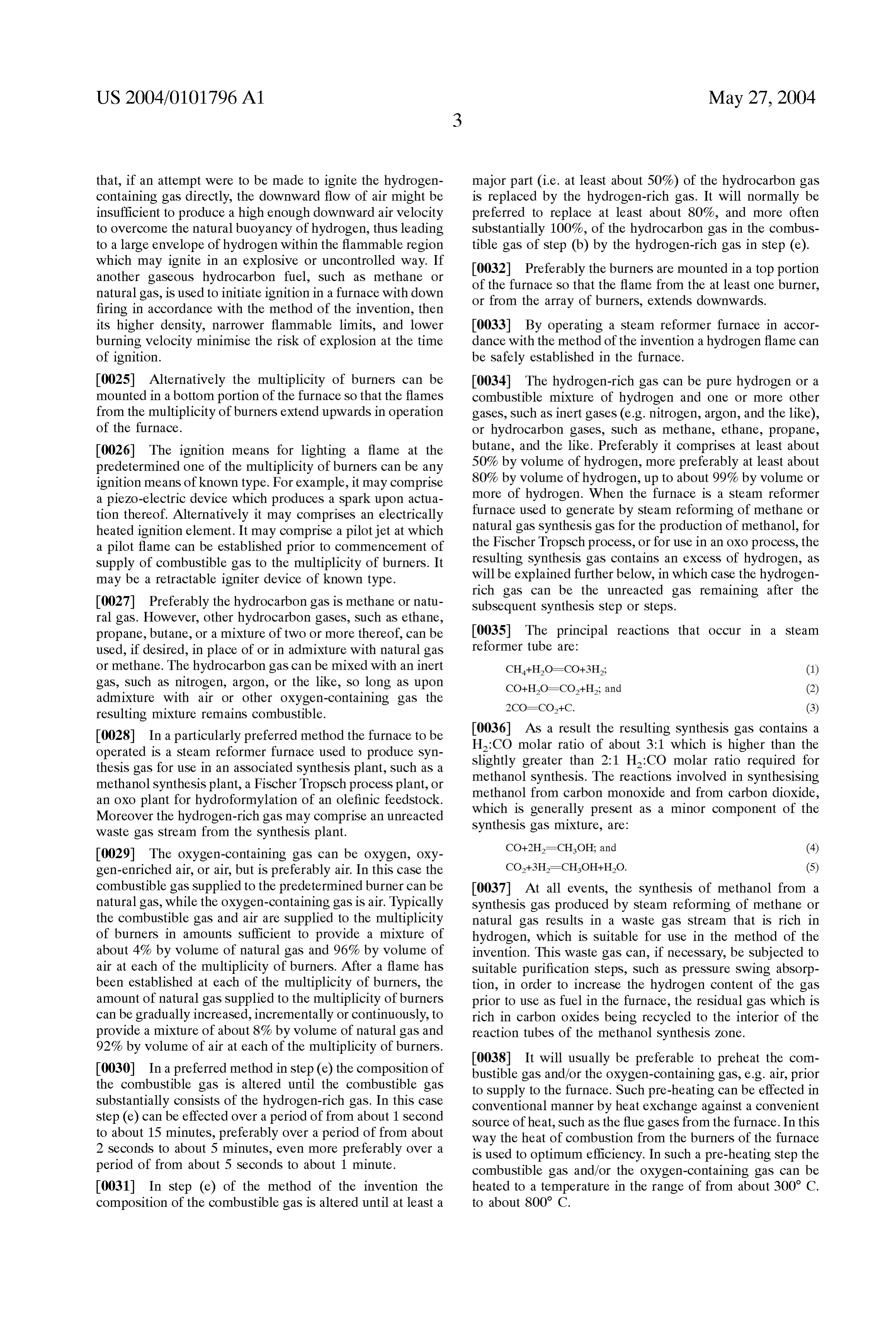
that, if an attempt were to be made to ignite the hydrogen major part (i.e. at least about 50%) of the hydrocarbon gas containing gas directly, the downward flow of air might be is replaced by the hydrogen-rich gas. It will normally be insufficient to produce a high enough downward air Velocity preferred to replace at least about 80%, and more often to overcome the natural buoyancy of hydrogen, thus leading substantially 100%, of the hydrocarbon gas in the combus to a large envelope of hydrogen within the flammable region tible gas of Step (b) by the hydrogen-rich gas in Step (e). which may ignite in an explosive or uncontrolled way. If 0032 Preferably the burners are mounted in a top portion another gaseous hydrocarbon fuel, Such as methane or of the furnace so that the flame from the at least one burner, natural gas, is used to initiate ignition in a furnace with down or from the array of burners, extends downwards. firing in accordance with the method of the invention, then its higher density, narrower flammable limits, and lower 0033. By operating a steam reformer furnace in accor burning Velocity minimise the risk of explosion at the time dance with the method of the invention a hydrogen flame can of ignition. be safely established in the furnace. 0.025 Alternatively the multiplicity of burners can be 0034. The hydrogen-rich gas can be pure hydrogen or a mounted in a bottom portion of the furnace So that the flames combustible mixture of hydrogen and one or more other from the multiplicity of burners extend upwards in operation gases, Such as inert gases (e.g. nitrogen, argon, and the like), of the furnace. or hydrocarbon gases, Such as methane, ethane, propane, 0026. The ignition means for lighting a flame at the butane, and the like. Preferably it comprises at least about predetermined one of the multiplicity of burners can be any 50% by volume of hydrogen, more preferably at least about ignition means of known type. For example, it may comprise 80% by volume of hydrogen, up to about 99% by volume or a piezo-electric device which produces a Spark upon actua more of hydrogen. When the furnace is a steam reformer tion thereof. Alternatively it may comprises an electrically furnace used to generate by Steam reforming of methane or heated ignition element. It may comprise a pilotjet at which natural gas Synthesis gas for the production of methanol, for a pilot flame can be established prior to commencement of the Fischer TropSch process, or for use in an OXO process, the Supply of combustible gas to the multiplicity of burners. It resulting Synthesis gas contains an excess of hydrogen, as may be a retractable igniter device of known type. will be explained further below, in which case the hydrogen rich gas can be the unreacted gas remaining after the 0.027 Preferably the hydrocarbon gas is methane or natu Subsequent Synthesis Step or Steps. ral gas. However, other hydrocarbon gases, Such as ethane, propane, butane, or a mixture of two or more thereof, can be 0035. The principal reactions that occur in a steam used, if desired, in place of or in admixture with natural gas reformer tube are:
or methane. The hydrocarbon gas can be mixed with an inert gas, Such as nitrogen, argon, or the like, So long as upon admixture with air or other oxygen-containing gas the resulting mixture remains combustible.
0028. In a particularly preferred method the furnace to be 0036) As a result the resulting synthesis gas contains a operated is a Steam reformer furnace used to produce Syn H:CO molar ratio of about 3:1 which is higher than the thesis gas for use in an associated Synthesis plant, Such as a slightly greater than 2:1 H:CO molar ratio required for methanol Synthesis plant, a Fischer TropSch process plant, or methanol Synthesis. The reactions involved in Synthesising an OXO plant for hydroformylation of an olefinic feedstock. methanol from carbon monoxide and from carbon dioxide, Moreover the hydrogen-rich gas may comprise an unreacted which is generally present as a minor component of the waste gas Stream from the Synthesis plant. Synthesis gas mixture, are:
0029. The oxygen-containing gas can be oxygen, oxy CO+2H=CH-OH; and (4) gen-enriched air, or air, but is preferably air. In this case the CO+3H=CH-OH-HO. (5) combustible gas Supplied to the predetermined burner can be 0037. At all events, the synthesis of methanol from a natural gas, while the oxygen-containing gas is air. Typically Synthesis gas produced by Steam reforming of methane or the combustible gas and air are Supplied to the multiplicity natural gas results in a waste gas Stream that is rich in of burners in amounts Sufficient to provide a mixture of hydrogen, which is suitable for use in the method of the about 4% by volume of natural gas and 96% by volume of invention. This waste gas can, if necessary, be Subjected to air at each of the multiplicity of burners. After a flame has Suitable purification Steps, Such as preSSure Swing absorp been established at each of the multiplicity of burners, the tion, in order to increase the hydrogen content of the gas amount of natural gas Supplied to the multiplicity of burners prior to use as fuel in the furnace, the residual gas which is can be gradually increased, incrementally or continuously, to rich in carbon oxides being recycled to the interior of the provide a mixture of about 8% by volume of natural gas and reaction tubes of the methanol Synthesis Zone. 92% by volume of air at each of the multiplicity of burners.
0038. It will usually be preferable to preheat the com 0030) In a preferred method in step (e) the composition of bustible gas and/or the oxygen-containing gas, e.g. air, prior the combustible gas is altered until the combustible gas to Supply to the furnace. Such pre-heating can be effected in Substantially consists of the hydrogen-rich gas. In this case conventional manner by heat eXchange against a convenient Step (e) can be effected over a period of from about 1 Second Source of heat, Such as the flue gases from the furnace. In this to about 15 minutes, preferably over a period of from about way the heat of combustion from the burners of the furnace 2 Seconds to about 5 minutes, even more preferably over a is used to optimum efficiency. In Such a pre-heating Step the period of from about 5 seconds to about 1 minute. combustible gas and/or the oxygen-containing gas can be 0031. In step (e) of the method of the invention the heated to a temperature in the range of from about 300 C. composition of the combustible gas is altered until at least a to about 800° C.
Page 7
US 2004/0101796 A1 May 27, 2004
0039. In a preferred method according to the invention added to a depth of 50 mm to fill the gap between tubes 16 the preheated combustible gas is Supplied, Separately from and burner tubes 17 So that about 100 mm of each of the the oxygen-containing gas, via a manifold to individual burner tubes 17 projets above the alumina spheres. The Supply tubes feeding respective burners. These individual burner tubes 17 are each supplied from a fuel manifold box Supply tubes are devoid of Supply control valves. The 18, which is 25 mm high, through a respective Single 2 mm oxygen-containing gas is preheated by heat eXchange with diameter hole 19. Each burner tube is surrounded by four the reformed gases and the hot oxygen-containing gas is apertures 14 for Supply of air thereto. This arrangement of used to heat the outside of the individual supply tubes burner tubes 17 and air Supply apertures 14 provides, in through which the combustible gas is Supplied So as to combination with the dispersing effect of the alumina preheat the combustible gas. spheres, an effective distribution of air to burner tubes 17 0040. When it is desired to shut down a furnace burning Similar to the forced air Supply to an open furnace chamber a hydrogen-rich fuel, the hydrogen-rich gas flow Stream can containing reformer tubes.
be switched to a flow of an equivalent amount by volume of 0046. In order to enable observation of the flames and inert gas, Such as nitrogen, while maintaining the flow of flame propagation, a glass window 20 is installed in the wall oxygen-containing gas. AS the inert gas replaces the hydro 3 of the longside of the rig. 1. The bottom of window 20 is gen-rich gas So the flame will be extinguished over a period level with the top end 21 of burner tubes 17. An 18 mm of time. After a sufficient period of flow of the inert gas the diameter hole 22 is provided in each of walls 2 and 4 and risk of explosion in the burner assembly is removed thus also in wall 7 with the bottom of hole 22 being level with the avoiding a possibility of blowback. Extinction of the flame top end 21 of burner tubes 17. This hole 22 can be used for will lead to cessation of the Steam reforming reaction and insertion of an oxygen-propane flame to act as pilot light to cooling of the reformed gases exiting the reaction tubes. By ignite the fuel from the adjacent burner tube 17 and provides maintaining a flow of air through the air inlet manifold, additional viewing facilities. A mirror (not shown) is posi cooling of the furnace can be assisted. tioned at an angle above the open top end 10 of the rig 1 in Such a way that observations can conveniently be made, 0041. In order that the invention may be clearly under looking down into the rig 1, without the observer being stood and readily carried into effect a preferred process in Subjected to heat and fumes.
accordance with the invention will now be described, by way of example only, with reference to the accompanying 0047 The invention is further illustrated in the following drawings, wherein:- Examples. In the Examples all gas flow rates are expressed
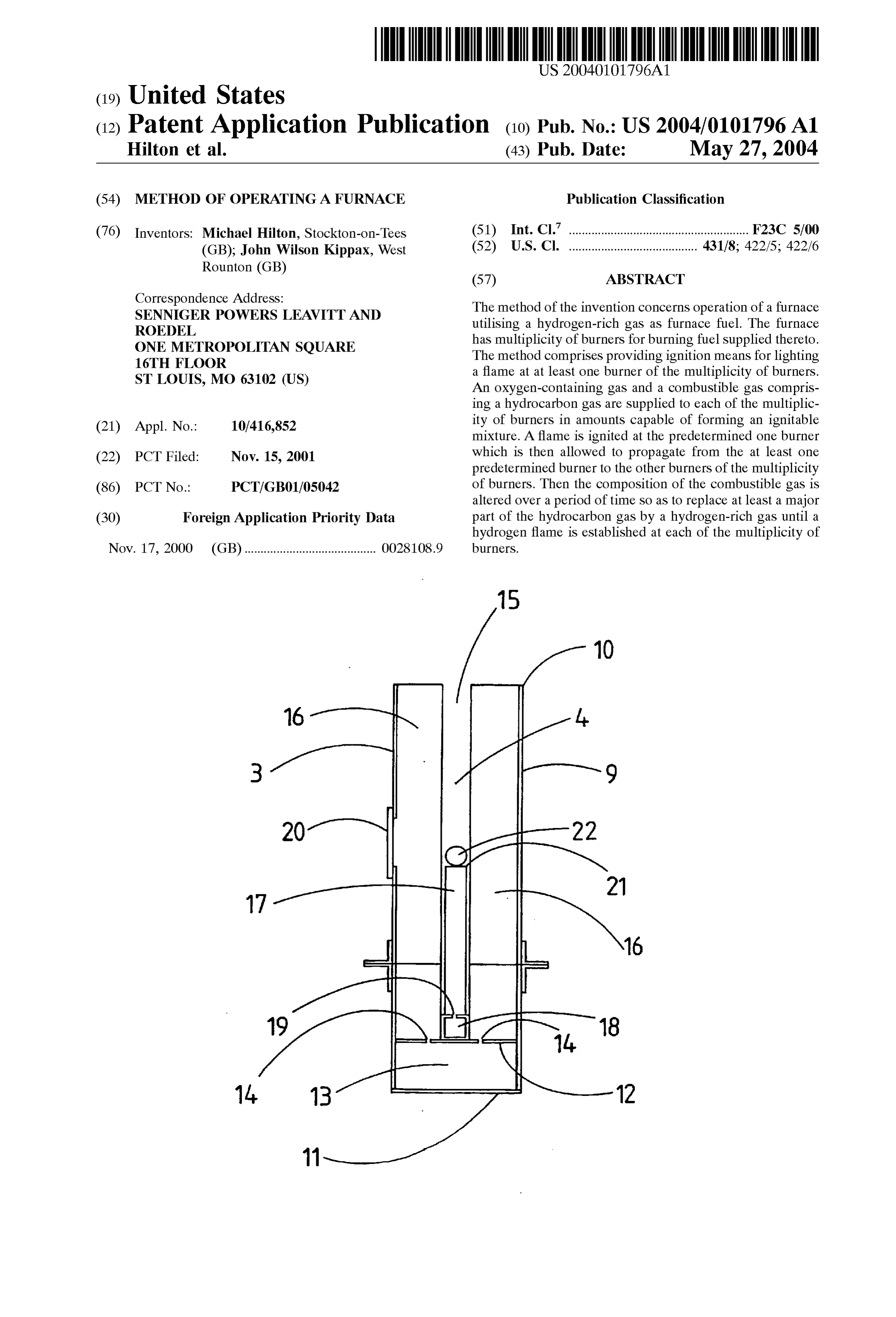
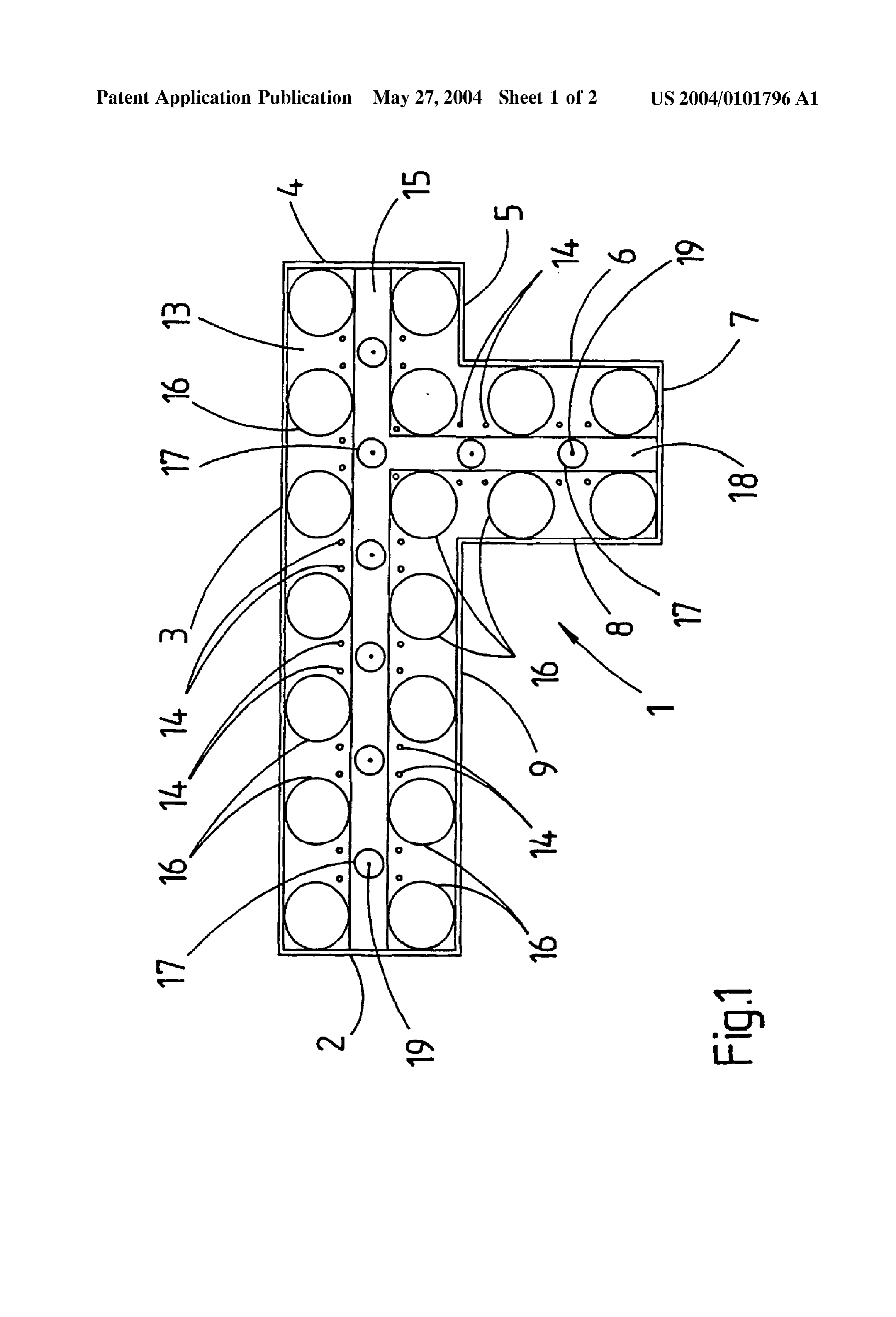
0.042 FIG. 1 is a top plan view of an experimental rig intended to Simulate part of the burner array and tube array EXAMPLE 1. of a compact reformer furnace of the type disclosed in
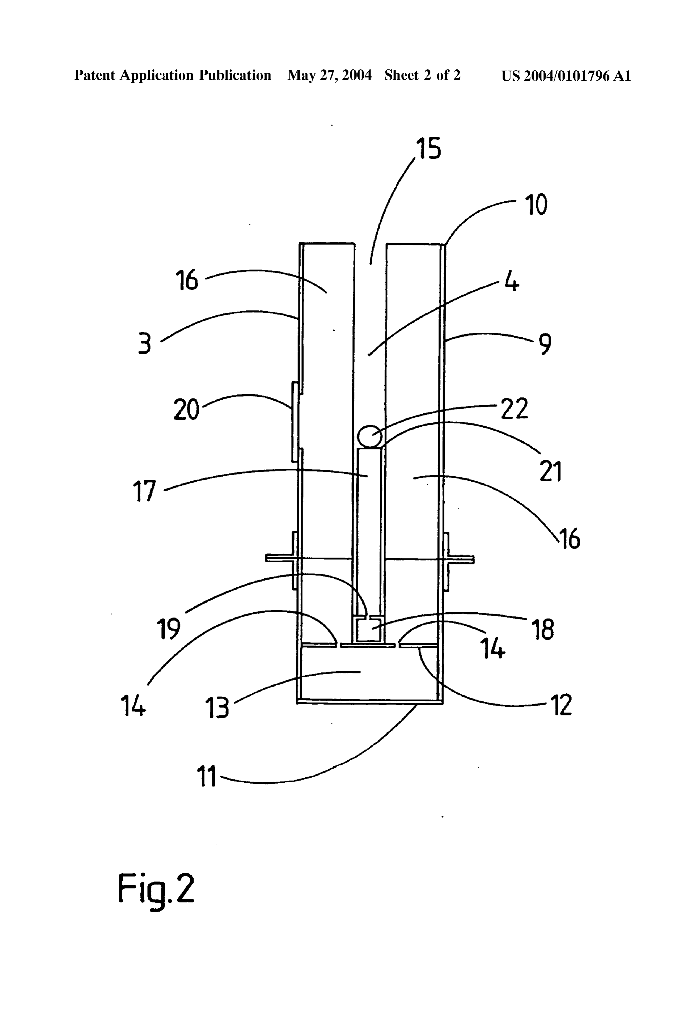
WO-A-94/29013; and 0048 Rig 1 was arranged to be supplied through fuel Supply box 18 with Substantially pure hydrogen gas as fuel 0.043 FIG. 2 is a vertical section through the experimen and through air collector box 13 with air. The flow rates tal rig of FIG. 1. could be measured using appropriate rotameters (not 0044) Referring to the drawings, there is shown an shown). A Series of tests was carried out each lasting only a experimental burner rig 1 which comprises a thermally few Seconds. The procedure adopted involved establishing insulated rectangular parallelipipedal box whose internal an air flow from air supply box 13 into the combustion dimensions are 470 mm longx115 mm wide by 1625 mm chamber 15 through apertures 14 and then establishing a fuel high, to which is attached a Second box 142 mm longx115 flow into burner tubes 17 from fuel Supply box 18 through mm widex 1625 mm high. There is no wall between the two apertures 19. An oxygen-propane pilot flame was first of all boxes and So the two boxes together form a box of generally inserted into one of the ignition holes 22 So that, when offset T-section. The walls of the rig are formed by mild steel hydrogen was Subsequently Supplied via manifold 18, a plates 2, 3, 4, 5, 6, 7, 8, and 9. The rig is open at its upper flame could be lit at the adjacent burner 17. If ignition did end 10 but has a closed lower end formed by mild steel not occur the fuel flow was stopped and the air flow was bottom plate 11. Above bottom plate 11 is a transverse plate changed to a new value. The fuel was then re-Supplied and 12 also made of mild steel which forms the top of an air ignition tried again. In Some cases the adjacent burner 17 to collector box 13 and the floor of a combustion space within the one lit with the oxygen-propane pilot flame would also the rig 1. Plate 12 is pierced with 3 mm diameter apertures light and propagation of flames to all burners would often 14 through which air for combustion can be drawn from air occur. A video recording was made of each ignition attempt. collector box 13 into a combustion chamber 15. All of the In those cases in which ignition occurred nitrogen was added joints on the rig were Sealed. to the combustion chamber 15 to extinguish the flames and the fuel Supply was stopped. Without nitrogen addition 0045. Within combustion chamber 15 there is mounted blow-backs were frequently observed. The fuel Supply was an array of eighteen aluminium tubes 16 of 45 mm outside then re-established at a new value and ignition attempted at diameter equally spaced on a 70 mm Square pitch. TubeS 16 a new flow rate as previously described. For each fuel flow are thus arranged to replicate the external shape of reformer rate a number of different air flow rates were tried. From the tubes in a compact reformer furnace. Spaced between the experiments it was determined that ignition and propagation tubes 16 and at the centre of the Square pitch are placed a was feasible over a hydrogen flow range between 1600 and total of eight burner tubes 17 which have an external 5000 1/h with a range of excess air flow rates of from about diameter of 19 mm and a length of 150 mm. Six burners 17 200% to about 400%. In other words ignition was feasible are arranged in a Straight line and two are in the Side branch using about 10% V/v to about 15% V/v hydrogen in air formed by walls 6, 7 and 8. Alumina spheres (not shown) are mixtures. However, it was observed that ignition and flame
Page 8
US 2004/0101796 A1 May 27, 2004
propagation using hydrogen as fuel was, in general, Violent (d) allowing a flame to propagate from the at least one and erratic. There was a distinct “pop” as each burner was predetermined burner to the other burners of the mul lit from the flame above each burner tube 17. It was noted tiplicity of burners, and that at higher fuel flow rates the release of energy was greater and judged to be too violent, especially with lower (e) altering the composition of the combustible gas over excess air flow rates. At lower fuel flow rates the flame a period of time So as to replace at least a major part of above the burner tubes 17 either did not form or was too the hydrocarbon gas by a hydrogen-rich gas until an at weak to provide Satisfactory propagation. This was also true least predominantly hydrogen flame is established at at higher exceSS air flow rates. It was noted that the calcu each of the multiplicity of burners. lated fuel/air mixture in Several of these unsatisfactory low 2. A method according to claim 1, wherein the multiplicity fuel flow rates was close to the reported lower flammability of burners is arranged in an array in the furnace Such that a limit of hydrogen in air of 4.0%. flame ignited at the at least one predetermined burner can propagate to each of the other burners of the array.
EXAMPLE 2 3. A method according to claim 1 or claim 2, wherein the 0049. The procedure of Example 1 was repeated except multiplicity of burners is mounted in a top portion of the that natural gas was used as fuel. It was determined that furnace so that the flames from the multiplicity of burners ignition and flame propagation was feasible over a natural extend downwards in operation of the furnace. gas flow rate between 1450 1/h and 2900 1/h with a range 4. A method according to claim 1 or claim 2, wherein the of excess air flows between about 80% and about 100%. It multiplicity of burners is mounted in a bottom portion of the was observed that ignition and propagation with natural gas furnace so that the flames from the multiplicity of burners was not violent and not erratic. extend upwards in operation of the furnace. 5. A method according to any one of claims 1 to 3,
EXAMPLE 3 wherein the furnace is a Steam reformer furnace having a 0050. The procedure of Example 2 was repeated with an plurality of reformer tubes, each containing a charge of a air flow of 35000 1/h and a natural gas flow of 1700 1/h such Steam reforming catalyst, the reformer tubes being arranged that a stable flame was established at each burner. A Series with their axes extending in a Substantially vertical direc of tests was then performed in which the natural gas flow tion, wherein the multiplicity of burners is arranged in an was replaced with hydrogen at a flow rate of 4800 1/h over array in a top portion of the furnace for heating the reformer about 5 seconds to about 60 seconds. There were no violent tubes to a Steam reforming temperature by means of flames or erratic changes in the flames and no explosions during or extending downwards from the multiplicity of burners, and after the transition between the fuels. wherein a reactant mixture comprising a mixture of Steam and a hydrocarbon feedstock to be reformed is passed
EXAMPLE 4 upwardly under Steam reforming conditions through the heated reformer tubes.
0051 Rig 1 is inverted with a wire mesh added to prevent 6. A method according to any one of claims 1 to 5, the alumina Spheres from falling out. The procedure of wherein the hydrocarbon gas comprises methane or natural Example 1 is repeated with Similar results except that the gaS.
flames fire downwards.
7. A method according to any one of claims 1 to 6,
EXAMPLE 5 wherein the furnace is a Steam reformer furnace used to produce Synthesis gas for a downstream Synthesis plant and 0.052 With rig 1 inverted the procedure of Example 2 is wherein the hydrogen-rich gas comprises an unreacted waste repeated with Similar results except that the flames fire gas Stream from the downstream Synthesis plant. downwards.
8. A method according to claim 7, wherein the down
EXAMPLE 6 Stream Synthesis plant is Selected from a methanol Synthesis plant, a Fischer Tropsch plant, and an OXO plant.
0053. The procedure of Example 3 is repeated with rig 1 9. A method according to any one of claims 1 to 8, still inverted. Similar results are obtained with the flames wherein the combustible gas Supplied to the predetermined firing downwards. burner in Step (b) is natural gas, wherein the oxygen containing gas is air, and wherein the combustible gas and 1. A method of operating a furnace utilising a hydrogen air are Supplied to the multiplicity of burners in amounts rich gas as furnace fuel, the furnace having a multiplicity of sufficient to provide a mixture of about 4% by volume of burners for burning fuel supplied thereto, which method natural gas and about 96% by volume of air at each of the comprises: multiplicity of burners.
(a) providing ignition means for lighting a flame at at least 10. A method according to claim 9, wherein, after a flame one predetermined burner Selected from the multiplic has been established at each of the multiplicity of burners, ity of burners; the amount of natural gas Supplied to the multiplicity of burners is increased, incrementally or continuously, to pro (b) Supplying to each of the multiplicity of burners an vide a mixture of about 8% by volume of natural gas and oxygen-containing gas and a combustible gas compris about 92% by volume of air.
ing a hydrocarbon gas in amounts capable of forming an ignitable mixture; 11. A method according to any one of claims 1 to 10, wherein in step (e) the composition of the combustible gas (c) igniting a flame at the at least one predetermined is altered until the combustible gas Substantially consists of burner; the hydrogen-rich gas.
Page 9
US 2004/0101796 A1 May 27, 2004
12. A method according to claim 11, wherein Step (e) is 14. A method according to claim 13, wherein the volume effected over a period of from about 5 seconds to about 1 flow rate of the hydrogen-rich gas during Step (e) is less than minute. about 25% of the full operating flow rate of hydrogen-rich 13. A method according to any one of claims 1 to 12, gas for which the furnace is designed. wherein the flow rate of hydrogen-rich gas during step (e) is reduced compared with the flow rate of hydrogen-rich gas during Subsequent operation of the furnace.

Provenance
- Collection
- Patents citing this work
- Current assignee
- Johnson Matthey Davy Technologies Ltd
- Pages
- 9
- Method
- pdftotext (the PDF's own text layer) + pdftoppm 300dpi page scans
- Patent office record
- patents.google.com →
- Source
- Google Patents citing-documents table
- Inventors
- Michael Hilton; John Kippax
- Published
- 2004-05-27
- Transcribed from
- patentimages.storage.googleapis.com →