patent · US4861347
Compact chemical reaction vessel
29 August 1989
Page 1 — bibliographic record
United States Patent (19) 11 Patent Number: 4,861,347 Szydlowski et al. 45) Date of Patent: Aug. 29, 1989 (54) COMPACT CHEMICAL REACTION VESSEL 3,541,729 11/1970 Dantowitz .............................. 48/94 3,909,299 9/1975 Corrigan ...... ... 422/198 (75) Inventors: Donald F. Szydlowski, Ellington; 4,378,336 3/1983 Yoon ............ ... 422/201 George T. Suljak, Vernon, both of 4,554,223 ll/1985 Yokoyama ................... . . . . . . . . . 429/20 Conn. FOREIGN PATENT DOCUMENTS 73) Assignee: International Fuel Cells Corporation, 1327210 4/1963. France ................................ 422/198 South Windsor, Conn.
(21) Appl. No.: 947,068 Primary Examiner-Peter Kratz (22 Filed: Dec. 29, 1986 (57) ABSTRACT The vessel is a fuel/steam reformer which has an annu 51) Int. Cl." ................................................ B01J 8/06 lar chamber containing a catalyst bed. The annular 52 U.S. C. ........................................... 48/61; 48/94; chamber is surrounded by a heating zone and heat pipes
58) Field of Search ............... 422/198, 202, 200, 201, from the heating zone extend through the interior of the 422/203, 204, 211, 212; 48/61, 94; 429/19 catalyst bed whereby the catalyst is concurrently heated from inside and outside of the bed. A burner is 56) References Cited positioned coaxially of the annular chamber to supply
1,396,358 11/1921 Cochrane ............................ 422/202 chamber below the catalyst bed and after vaporization, 2,078,948 5/1937 Houdry ............ ... 422/200 rises through the catalyst bed for conversion to a hydro 2,115,714 5/1938 Houdry et al.... ... 422/211 gen rich fuel gas. The fuel gas is collected in a chamber 2,433,620 12/1947 Kropp .............. ... 422/200 above the catalyst bed. The device is particularly useful 3,144,312 8/1964 Mertens ... ... 422/198 for compact methanol fuel cell power plants. 3,278,268 10/1966 Pfefferle ... ... 422/198 3,441,446 4/1969 Heredy ..... ... 136/100 3,499,797 3/1970 Hooper ................................. 36/86 5 Claims, 3 Drawing Sheets
Page 2
Drawing sheet — no readable text.
Page 3
Drawing sheet — no readable text.
Page 4
Drawing sheet — no readable text.
Page 5
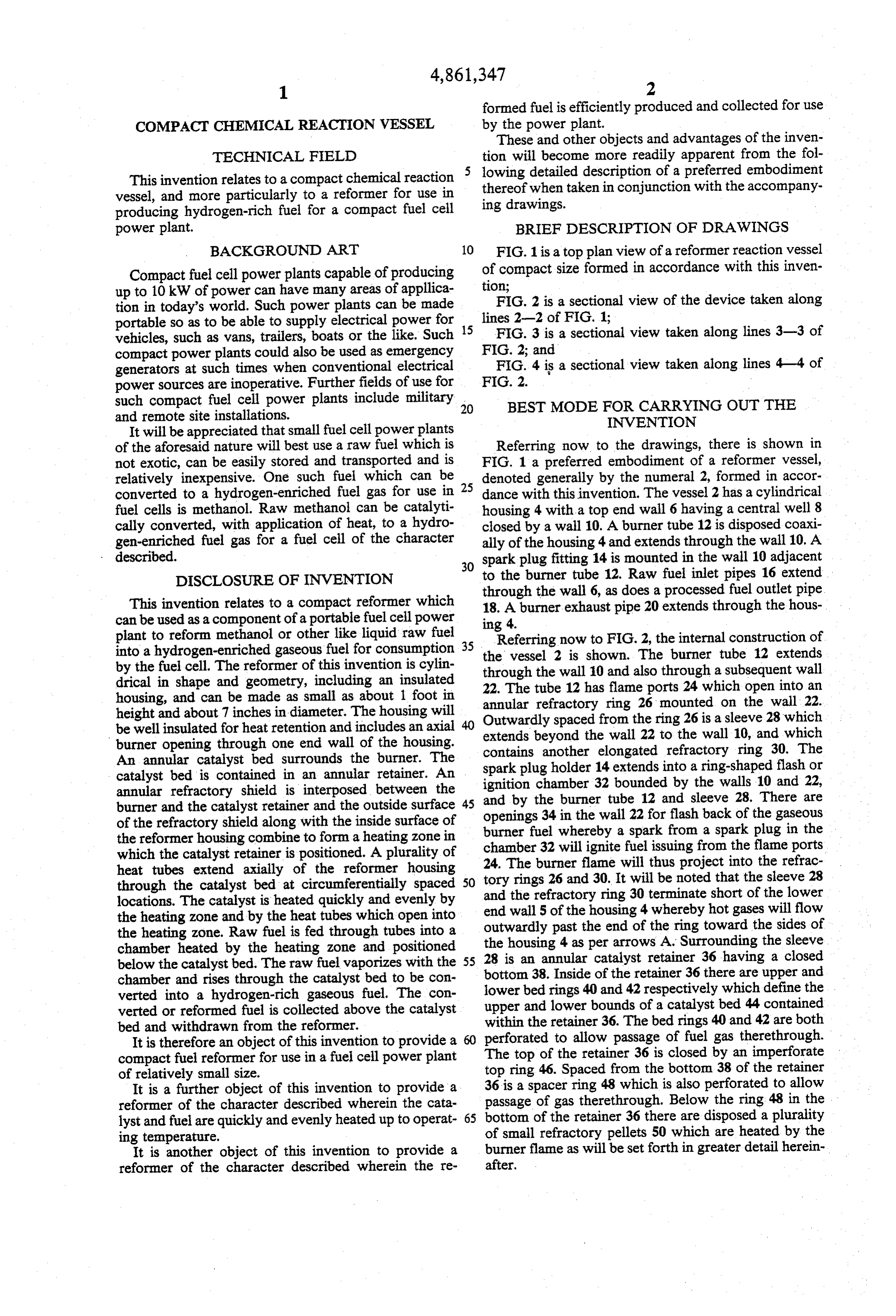
formed fuel is efficiently produced and collected for use
COMPACT CHEMICAL REACTION VESSEL by the power plant.
These and other objects and advantages of the inven
TECHNICAL FIELD tion will become more readily apparent from the fol This invention relates to a compact chemical reaction lowing detailed description of a preferred embodiment vessel, and more particularly to a reformer for use in thereof when taken in conjunction with the accompany producing hydrogen-rich fuel for a compact fuel cell ing drawings.
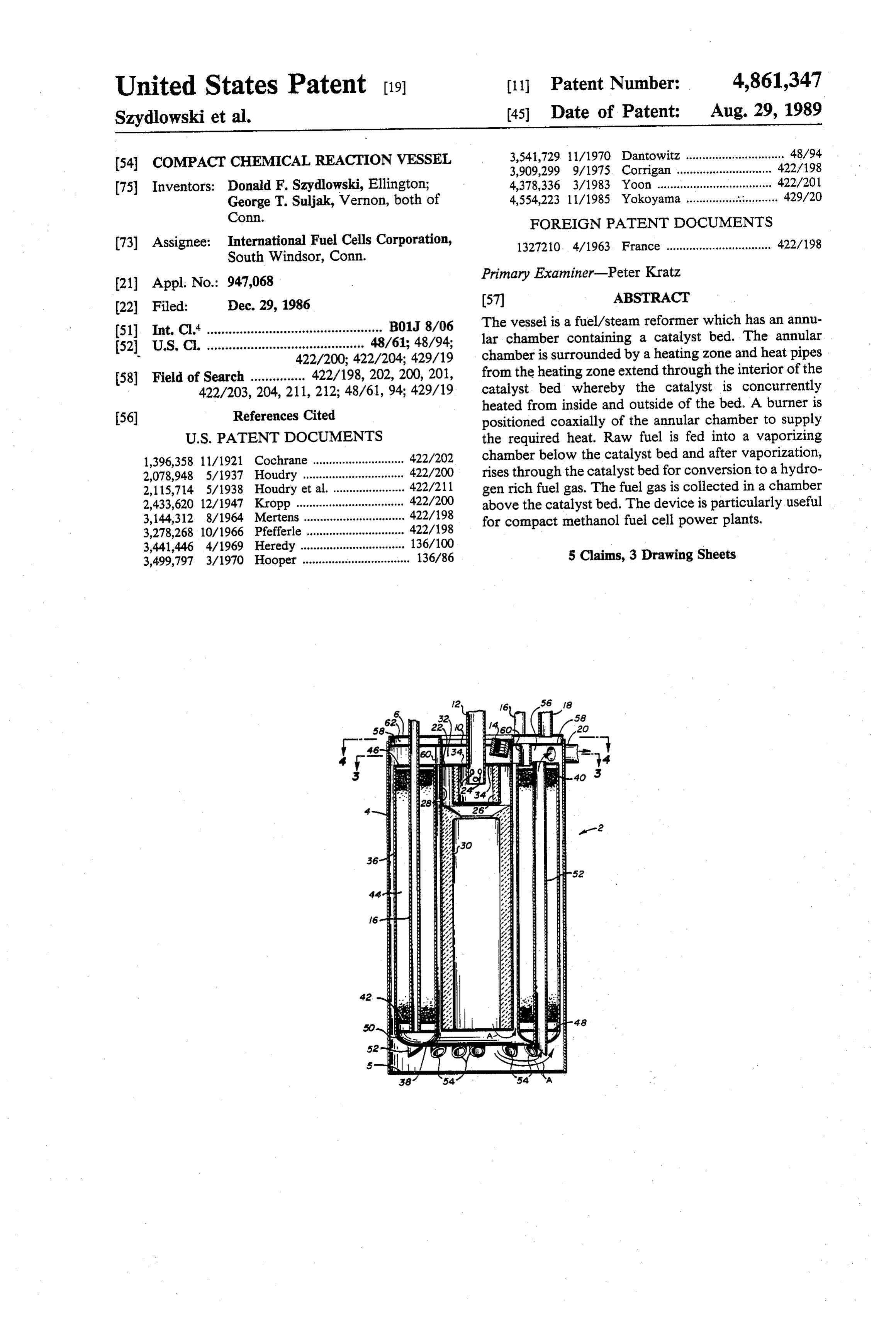
power plant. BRIEF DESCRIPTION OF DRAWINGS BACKGROUND ART 10 FIG. 1 is a top plan view of a reformer reaction vessel Compact fuel cell power plants capable of producing of compact size formed in accordance with this inven up to 10 kW of power can have many areas of applica tion;
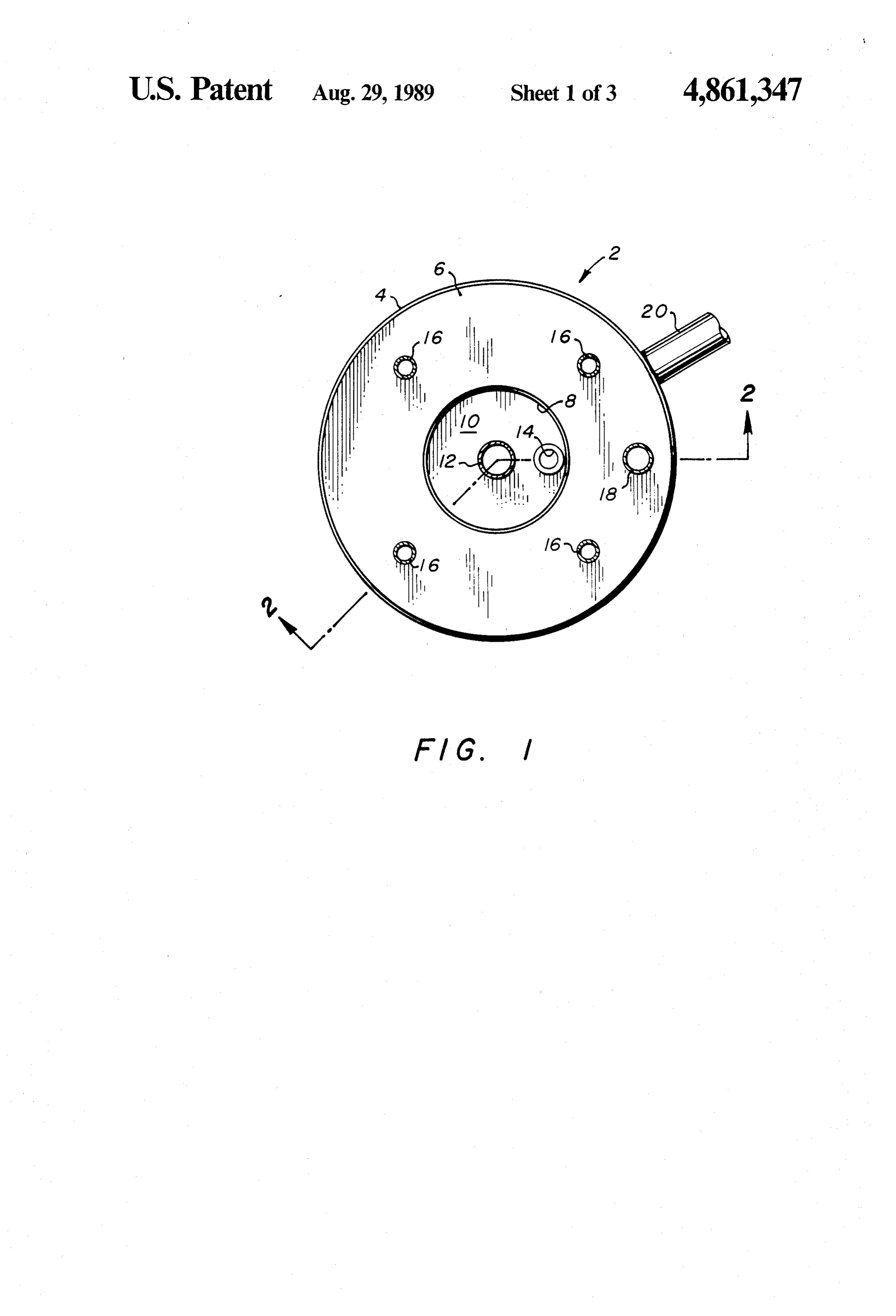
tion in today's world. Such power plants can be made FIG. 2 is a sectional view of the device taken along portable so as to be able to supply electrical power for 15 lines 2-2 of FIG. 1;
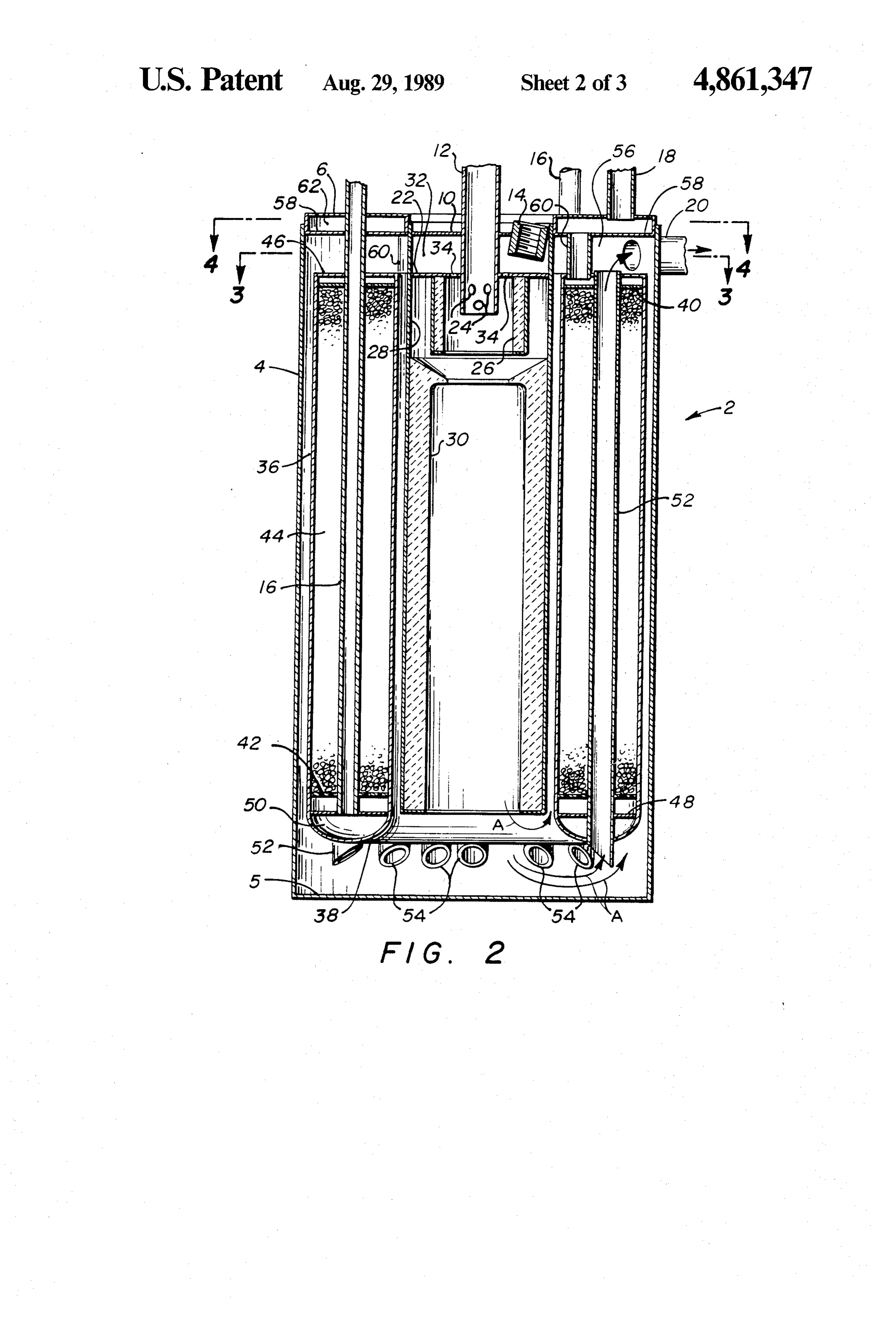
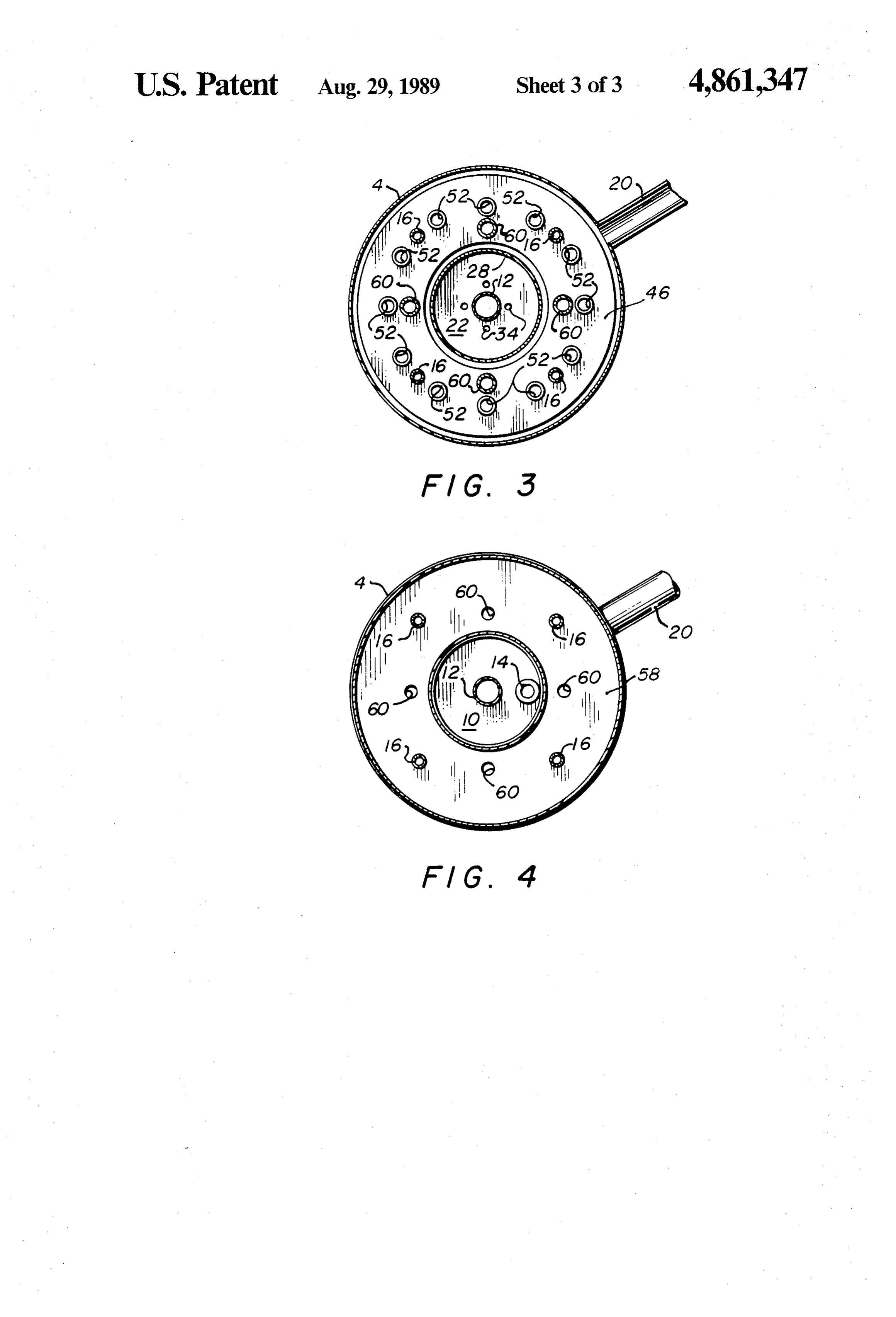
vehicles, such as vans, trailers, boats or the like. Such FIG. 3 is a sectional view taken along lines 3-3 of compact power plants could also be used as emergency FIG. 2; and generators at such times when conventional electrical FIG. 4 is a sectional view taken along lines 4-4 of power sources are inoperative. Further fields of use for FIG. 2.
such compact fuel cell power plants include military 20 BEST MODE FOR CARRYING OUT THE and remote site installations. INVENTION
It will be appreciated that small fuel cell power plants of the aforesaid nature will best use a raw fuel which is Referring now to the drawings, there is shown in not exotic, can be easily stored and transported and is FIG. 1 a preferred embodiment of a reformer vessel, relatively inexpensive. One such fuel which can be denoted generally by the numeral 2, formed in accor converted to a hydrogen-enriched fuel gas for use in 25 dance with this invention. The vessel 2 has a cylindrical fuel cells is methanol. Raw methanol can be catalyti housing 4 with a top end wall 6 having a central well 8 cally converted, with application of heat, to a hydro closed by a wall 10. A burner tube 12 is disposed coaxi gen-enriched fuel gas for a fuel cell of the character ally of the housing 4 and extends through the wall 10. A 30 sparkplug fitting 14 is mounted in the wall 10 adjacent described.
DISCLOSURE OF INVENTION to the burner tube 12. Raw fuel inlet pipes 16 extend through the wall 6, as does a processed fuel outlet pipe
This invention relates to a compact reformer which 18. A burner exhaust pipe 20 extends through the hous can be used as a component of a portable fuel cell power ing 4.
plant to reform methanol or other like liquid raw fuel 35 Referring now to FIG. 2, the internal construction of into a hydrogen-enriched gaseous fuel for consumption the vessel 2 is shown. The burner tube 12 extends by the fuel cell. The reformer of this invention is cylin drical in shape and geometry, including an insulated through22. The the wall 10 and also through a subsequent wall tube 12 has flame ports 24 which open into an housing, and can be made as small as about 1 foot in height and about 7 inches in diameter. The housing will annular refractory ring 26 mounted on the wall 22. Outwardly spaced from the ring 26 is a sleeve 28 which be well insulated for heat retention and includes an axial burner opening through one end wall of the housing. containsbeyond extends another the wall 22 to the wall 10, and which elongated refractory ring 30. The
An annular catalyst bed surrounds the burner. The spark plug holder 14 extends into a ring-shaped flash or catalyst bed is contained in an annular retainer. An annular refractory shield is interposed between the ignition chamber 32 bounded by the walls 10 and 22, and by the burner tube 12 and sleeve 28. There are burner and the catalyst retainer and the outside surface 45 openings 34 in the wall 22 for flash back of the gaseous of the refractory shield along with the inside surface of burner fuel whereby a spark from a spark plug in the the reformer housing combine to form a heating zone in which the catalyst retainer is positioned. A plurality of chamber 32 will ignite fuel issuing from the flame ports heat tubes extend axially of the reformer housing 24. The burner flame will thus project into the refrac tory rings 26 and 30. It will be noted that the sleeve 28 through the catalyst bed at circumferentially spaced 50 and the refractory ring 30 terminate short of the lower locations. The catalyst is heated quickly and evenly by end wall the heating zone and by the heat tubes which open into outwardly5 of the housing 4 whereby hot gases will flow the heating zone. Raw fuel is fed through tubes into a the housingpast the end of the ring toward the sides of chamber heated by the heating zone and positioned 28 is an annular per 4 as arrows A. Surrounding the sleeve catalyst retainer 36 having a closed below the catalyst bed. The raw fuel vaporizes with the 55 bottom 38. Inside of the retainer 36 there are upper and chamber and rises through the catalyst bed to be con verted into a hydrogen-rich gaseous fuel. The con lower bed rings 40 and 42 respectively which define the verted or reformed fuel is collected above the catalyst upper and lower bounds of a catalyst bed 44 contained bed and withdrawn from the reformer. within the retainer 36. The bed rings 40 and 42 are both It is therefore an object of this invention to provide a perforated to allow passage of fuel gas therethrough. compact fuel reformer for use in a fuel cell power plant The top of the retainer 36 is closed by an imperforate top ring 46. Spaced from the bottom 38 of the retainer of relatively small size.
It is a further object of this invention to provide a 36 is a spacer ring 48 which is also perforated to allow passage of gas therethrough. Below the ring 48 in the reformer of the character described wherein the cata lyst and fuel are quickly and evenly heated up to operat 65 bottom of the retainer 36 there are disposed a plurality ing temperature. of small refractory pellets 50 which are heated by the It is another object of this invention to provide a burner flame as will be set forth in greater detail herein reformer of the character described wherein the re after,
Page 6
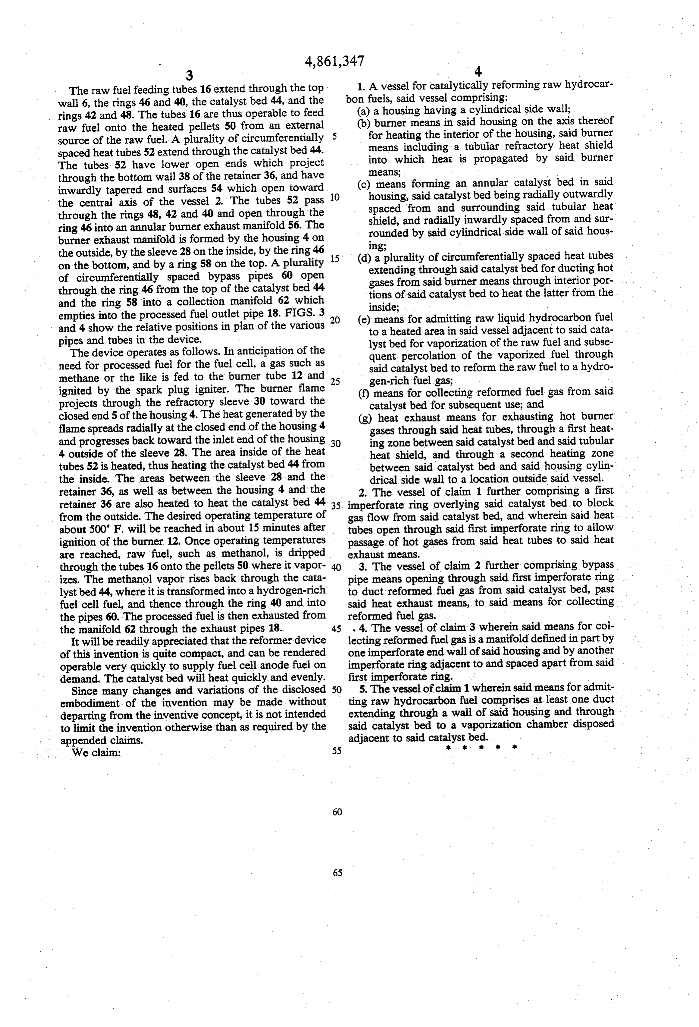
The raw fuel feeding tubes 16 extend through the top 1. A vessel for catalytically reforming raw hydrocar wall 6, the rings 46 and 40, the catalyst bed 44, and the bon fuels, said vessel comprising: rings 42 and 48. The tubes 16 are thus operable to feed (a) a housing having a cylindrical side wall; raw fuel onto the heated pellets 50 from an external (b) burner means in said housing on the axis thereof source of the raw fuel. A plurality of circumferentially 5 for heating the interior of the housing, said burner spaced heat tubes 52 extend through the catalyst bed 44. means including a tubular refractory heat shield The tubes 52 have lower open ends which project into which heat is propagated by said burner through the bottom wall 38 of the retainer 36, and have means;
inwardly tapered end surfaces 54 which open toward (c) means forming an annular catalyst bed in said the central axis of the vessel 2. The tubes 52 pass 10 housing, said catalyst bed being radially outwardly through the rings 48, 42 and 40 and open through the spaced from and surrounding said tubular heat shield, and radially inwardly spaced from and sur ring 46 into an annular burner exhaust manifold 56. The rounded by said cylindrical side wall of said hous burner, exhaust manifold is formed by the housing 4 on ling;
the outside, by the sleeve 28 on the inside, by the ring 46 on the bottom, and by a ring 58 on the top. A plurality 15 (d)extending a plurality of circumferentially spaced heat tubes through said catalyst bed for ducting hot of circumferentially spaced bypass pipes 60 open gases from said burner means through interiorpor through the ring 46 from the top of the catalyst bed 44 tions of said catalyst bed to heat the latter from the and the ring 58 into a collection manifold 62 which empties into the processed fuel outlet pipe 18. FIGS. 3 20 (e)inside; means for admitting raw liquid hydrocarbon fuel and 4 show the relative positions in plan of the various to a heated area in said vessel adjacent to said cata pipes and tubes in the device. lyst bed for vaporization of the raw fuel and subse The device operates as follows. In anticipation of the quent percolation of the vaporized fuel through need for processed fuel for the fuel cell, a gas such as said catalyst bed to reform the raw fuel to a hydro methane or the like is fed to the burner tube 12 and 25 gen-rich fuel gas;
ignited by the spark plug igniter. The burner flame (f) means for collecting reformed fuel gas from said projects through the refractory sleeve 30 toward the catalyst bed for subsequent use; and closed end 5 of the housing 4. The heat generated by the (g) heat exhaust means for exhausting hot burner flame spreads radially at the closed end of the housing 4 gases through said heat tubes, through a first heat and progresses back toward the inlet end of the housing 30 ing zone between said catalyst bed and said tubular 4 outside of the sleeve 28. The area inside of the heat heat shield, and through a second heating zone tubes 52 is heated, thus heating the catalyst bed 44 from between said catalyst bed and said housing cylin the inside. The areas between the sleeve 28 and the drical side wall to a location outside said vessel. retainer 36, as well as between the housing 4 and the 2. The vessel of claim 1 further comprising a first retainer 36 are also heated to heat the catalyst bed 44.35 imperforate ring overlying said catalyst bed to block from the outside. The desired operating temperature of gas flow from said catalyst bed, and wherein said heat about 500' F. will be reached in about 15 minutes after tubes open through said first imperforate ring to allow ignition of the burner 12. Once operating temperatures passage of hot gases from said heat tubes to said heat are reached, raw fuel, such as methanol, is dripped exhaust means.
through the tubes 16 onto the pellets 50 where it vapor- 40 3. The vessel of claim 2 further comprising bypass izes. The methanol vapor rises back through the cata pipe means opening through said first imperforate ring lyst bed 44, where it is transformed into a hydrogen-rich to duct reformed fuel gas from said catalyst bed, past fuel cell fuel, and thence through the ring 40 and into said heat exhaust means, to said means for collecting the pipes 60. The processed fuel is then exhausted from reformed fuel gas.
the manifold 62 through the exhaust pipes 18. 45 . 4. The vessel of claim 3 wherein said means for col It will be readily appreciated that the reformer device lecting reformed fuel gas is a manifold defined in part by of this invention is quite compact, and can be rendered one imperforate end wall of said housing and by another operable very quickly to supply fuel cell anode fuel on imperforate ring adjacent to and spaced apart from said demand. The catalystbed will heat quickly and evenly. first imperforate ring.
Since many changes and variations of the disclosed 50 5. The vessel of claim 1 wherein said means for admit embodiment of the invention may be made without ting raw hydrocarbon fuel comprises at least one duct departing from the inventive concept, it is not intended extending through a wall of said housing and through to limit the invention otherwise than as required by the said catalyst bed to a vaporization chamber disposed appended claims. adjacent to said catalyst. . bed.
Provenance
- Collection
- Cited prior art
- Original PDF
- patentimages.storage.googleapis.com →
- Filed
- 1986-12-29
- Pages
- 6
- Method
- pdftotext (the PDF's own text layer) + pdftoppm 300dpi page scans
- Source
- Google Patents bibliographic record
- Granted
- 1989-08-29
- Inventors
- Donald F. Szydlowski; George T. Suljak; International Fuel Cells Corp
- Transcribed from
- patentimages.storage.googleapis.com →