patent · US5372497
Process and apparatus for igniting a burner in an inert atmosphere
13 December 1994
Page 1 — bibliographic record
United States Patent (19) 11) Patent Number: 5,372,497 Coolidge et al. (45) Date of Patent: Dec. 13, 1994
54 APROCESS AND APPARATUS FORIGNITING
BURNER IN AN INERTATMOSPHERE OTHER PUBLICATIONS Forging Coal's New Future, SGI International, 6 pages, no date.
(75 Inventors: Dennis W. Coolidge, Katy, Tex.;
Franklin G. Rinker, Perrysburg, Strational 1991 Annual Report, Mar. 17, 1992, Ohio A Good Planet is Hard to Find, SGI International, 8 pages, no date.
(73) Assignee: SGI International, La Jolla, Calif. Primary Examiner-Carroll B. Dority Attorney, Agent, or Firm-Willian Brinks Hofer Gilson 21 Appl. No.: 66,345 & Lione
(22 Filed: May 24, 1993 According to this invention there is provided a process and apparatus for the ignition of a pilot burner in an (51) Int, Cl. .............................................. F23NS/20 inert atmosphere without substantially contaminating (52) U.S. C. .......................................... 431/6; 431/31; the inert atmosphere. The process includes the steps of 431/48; 431/60,431/283 providing a controlled amount of combustion air for a 58) Field of Search ................... 431/6, 30, 31, 49, 48, predetermined interval of time to the combustor then 431/46, 60, 175, 283 substantially simultaneously providing a controlled mixture of fuel and air to the pilot burner and to a flame 56) References Cited generator. The controlled mixture of fuel and air to the
flame generator is then periodically energized to pro duce a secondary flame. With the secondary flame the 2,755,852 7/1956 Andrews et al. ..................... 431/46 controlled mixture of fuel and air to the pilot burner and 2,986,207 5/1961 Scogin ............. ... 431/283 the combustion air is ignited to produce a pilot burner 3,086,583 4/1963 Reichow ............................... 431/46 flame. The pilot burner flame is then used to ignited a 3,677,533 7/1972 Oliver et al. .......................... 263/52 mixture of main fuel and combustion air to produce a 3,759,795 9/1973 Oliver et al........................... 201/25 main burner flame. The main burner flame then is used 4,089,628 5/1978 Blackburn ............................... 431/6 to ignite a mixture of process derived fuel and combus 4,395,309 7/1983 Esztergar .............................. 201/22 4,521,278 6/1985 Kelley et al. ......................... 201/17 tion air to produce products of combustion for use as an 4,548,577 10/1985 McGill ................ ..., 431/202 inert gas in a heat treatment process. 4,634,369 1/1987 McGill et al. .......................... 431/3 4,924,785 5/1990 Schultz et al. ...................... 110/346 28 Claims, 7 Drawing Sheets
COMBUSTION AIR
POT
Page 2
Drawing sheet — no readable text.
Page 3
Drawing sheet — no readable text.
Page 4
Drawing sheet — no readable text.
Page 5
Drawing sheet — no readable text.
Page 6
Drawing sheet — no readable text.
Page 7
NITIA E
CLOSE WALVES
CHECK IGNITERO OFF
NER SYSTEM
TIMER
NITIATE
PLOT
BURNER
OPEN
VALVES CLOSE WALVES
OPEN VALVES OPEN VALVES ,9 76 & 78 START
(37%O OPEN) TIMER(I5 SEC)
START PILOT START GNITER O
TIMER(3OSEC) AFTER 5 SEC.
DELAY
Page 8
Drawing sheet — no readable text.
Page 9
from air, carbon dioxide from combustion and water
PROCESS AND APPARATUS FORIGNITING A vapor from combustion or from the drying process are BURNER IN AN INERTATMOSPHERE recycled within the system except for controlled vent
FIELD OF THE INVENTION
ing. Similarly, as used herein, renewal of both the inert gas components and the sensible energy means that a
This invention relates to a process and apparatus for portion of the recirculated gas stream is mixed with air igniting a burner in an inert atmosphere. More particu in a combustion chamber to release heat and to oxidize larly, this invention relates to a process and apparatus a portion of combustible vapors and gases which result for igniting a burner in an inert atmosphere for produc O from the thermal process, and as may be picked up in ing an oxygen deficient gas stream used in the heat the recycle process. The recycling and renewal of the treatment of gas permeable, solid carbonaceous materi inert gas and utilization of process derived low calorific als. inert gas facilitates the possibility of an economically BACKGROUND OF THE INVENTION feasible advanced heat treatment process for combusti ble materials such as gas permeable, solid carbonaceous
This invention is concerned with the ignition of fuel 15 materials.
and air mixtures within an inert atmosphere. As used It will be appreciated that it is difficult to ignite a pilot herein the term "inert atmosphere” refers to an atmo and/or a burner in an inert atmosphere so as not to sphere unsuitable to support combustion, e.g. contain contaminate the inert composition of the recirculated ing no more than 10% oxygen. It will be appreciated, gases in either the coal drying process or mild coal for safety reasons, it is preferred that the inert atmo 20 gasification process. Furthermore, the presence of vola sphere in accordance with the present invention contain tile combustible materials necessitates that the inert no more than 5% oxygen and such other components as desired, e.g., N2, CO2, water vapor and hydrocarbons. atmosphere during within the system be maintained, especially ignition or reignition to prevent the inadvertent
It is known that various closed gaseous systems oper combustion of the combustible materials. ate with significant concentrations of unburned hydro 25 carbons in an inert high temperature gaseous atmo provide a method ofaspect
Accordingly, one of the present invention is to igniting a flame in an inert atmo sphere used for the processing of combustible materials. sphere without substantially changing the inert nature During start-up and perhaps, more significantly, during of the gaseous atmosphere within the system or permit restart of a burner it is necessary to provide a means to ting significant entry of oxygen for unintentional igni effect the ignition of the burner without substantially 30 altering the inert nature of the atmosphere during this tion of the hydrocarbons contained in the system. The present invention is particularly applicable for igniting transitory condition. As used herein the term "closed” both a pilot flame and a main burner flame useful in the refers to a system that is isolated from ambient condi production of large continuously flowing volumes of tionS.
For example, one closed system is disclosed in U.S. 35 inert gas as may be required for bulk drying and mild patent application Ser, No. 08/029556, filed Mar. 11, gasification of substantially continuously flowing 1993 and contains unburned hydrocarbons and is useful streams of coal or other carbonaceous free flowing bulk for increasing the thermal energy released during dry solids. The on-gas streams are recycled meaning that ing and gasification of coal by utilizing large volumes of the inerts, (i.e., nitrogen from air, carbon dioxide from continuously flowing streams of inert gas for convec 40 the combustion reaction and water vapor from either tive heat transfer. Inert gas as used herein refers to a gas the combustion reaction or from drying) remain except having generally less than 5% oxygen by weight. for venting, and are utilized repetitively. Heretofore, inert gas streams have typically been SUMMARY OF THE INVENTION produced using well known air separation technologies such as cryogenic distillation, membrane separation and 45 Briefly, according to this invention there is provided pressure swing absorption. Although the known meth a process for igniting a burner of a combustor to pro ods of producing inert gas streams for coal drying and duce a burner flame within a closed system containing mild gasification processes have been proven to per an inert atmosphere without substantially contaminat form satisfactorily in certain applications, these technol ing the inert atmosphere. The process includes the steps ogies are cost ineffective when considered for large 50 of purging the combustor to establish an inert atmo processing needs like mild coal gasification, coke pre sphere within the combustor and supplying a controlled heating and the like. Large mild coal gasification sys amount of combustion air for a predetermined interval tems may range up to 8,000 square feet and may use of time to the combustor. A controlled mixture of fuel 5,000 to 10,000 standard cubic feet of inert gas per hour and air is then substantially simultaneously supplied to a per square foot of cross section for thermal treatment of 55 pilot burner and to a flame generator. The controlled coal and/or oil shale whether the coal and/or oil shale mixture of fuel and air to the flame generator is periodi is to be dried or fractioned into solid and gaseous phase cally energized to produce a secondary flame. The components. Secondary flame then ignites the controlled mixture of A preferred method for recycling of an oxygen defi fuel and air to the pilot burner and the combustion air to cient gas stream used in the heat treatment of combusti produce a pilot burner flame. After ignition of the pilot ble materials includes a coal drying process and a mild burner flame a controlled amount of fuel and air is sup coal gasification process employing, in combination, plied to the main burner within the combustor which is recycling of inert gas and renewal of both the inert gas then ignited with the pilot burner flame to produce a components and the sensible energy. The preferred main burner flame. After the main burner flame is ig method requires precise control of inert gas chemistry, 65 nited a controlled amount of process derived fuel and gas supply temperature and advanced flammable gas air is supplied to the primary burner within the combus and vapor handling technology. As used herein, recy tor and ignited with the main burner flame to produce a cled inert gas means that the inert gas, i.e., nitrogen primary burner flame.
Page 10
The process of the present invention is achieved by a being conventional and well within the skill of the art pilot burner apparatus including a second valve means once the invention is disclosed and explained. Refer for selectively introducing a controlled amount of com ence is made to COMBUSTION TECHNOLOGY bustion air to the combustor, a third valve means for MANUAL, 4th Edition, Industrial Heating Equipment selectively unblocking pilot fuel and pilot air to a pilot Association, Virginia, 1988, Perry and Chilton, CHEM burner and a fourth valve means for selectively un ICAL ENGINEERS HANDBOOK, 5th Edition, blocking flame generator fuel and flame generator air to McGraw Hill, New York, 1973, and to the chemical a secondary flame generator including an energizer and processing industry literature generally for detailed a firing tube. The energizer, positioned external of the descriptions on the various apparatus and processing combustor, intermittently energizes the flame generator 10 structures and conditions. For example, a combustor 22 fuel and flame generator air to produce a secondary and 24, pyrolyzer 16, a dryer 18, piping 19, blowers 21 flame internal of the combustor within the firing tube to and valves may be any such known commercially avail ignite the controlled mixture of pilot fuel, pilot air and able components with the exception that such compo combustion air to produce a primary pilot flame internal nents may be modified as necessary by one skilled in the of the combustor. Subsequently, the primary pilot flame 15 art to be employed in the overall system 10 of the pres may ignite a mix of main fuel from a first valve means ent invention as discussed herein. In addition, many and combustion air to produce a main burner flame for control devices which are conventional and standard in combustion of a process derived fuel and primary air chemical processing have been omitted for clarity of within the combustor and generation of products of illustrating and describing the invention. For example, combustion for use as an inert gas. 20 control valves, thermocouples, thermistors, coupled Unless otherwise indicated, as used herein the term with suitable servo circuits are readily available and “fuel” refers to any material that is burnt to release conventionally used for measuring and controlling tem thermal energy whether the "fuel” is a process derived perature and process flow.
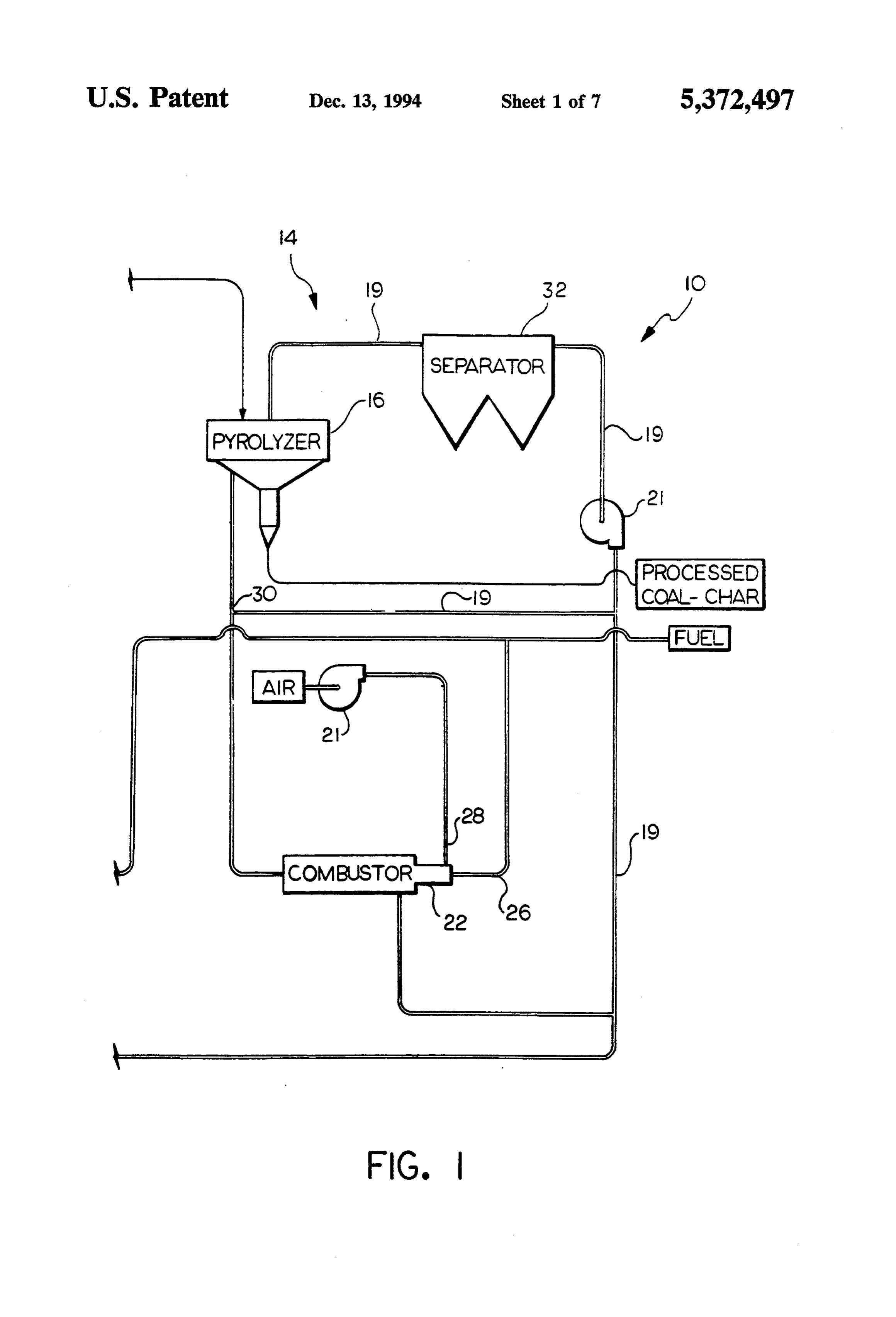
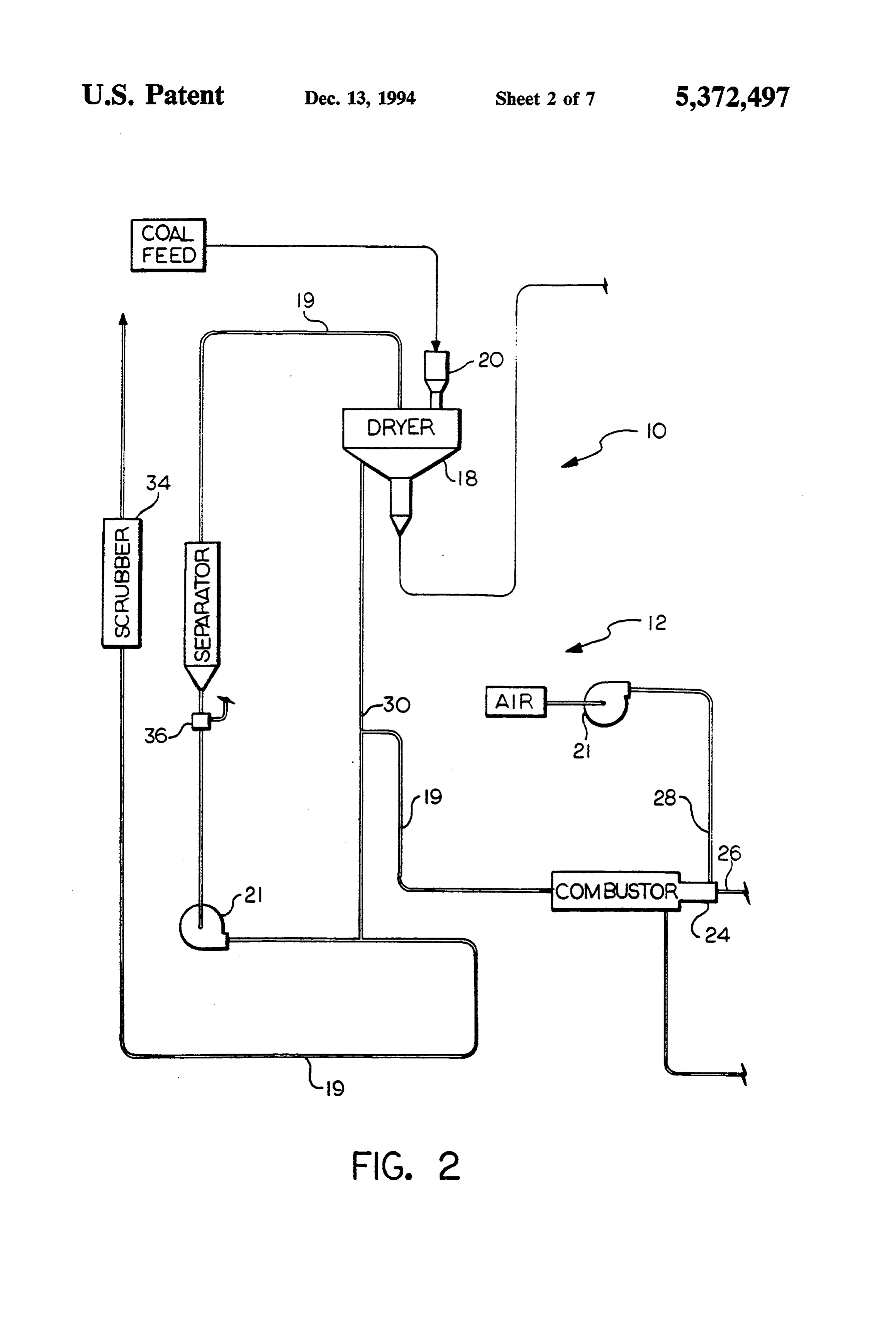
fuel, or an externally supplied fuel, (e.g., methane), or a Referring to FIGS. 1 and 2, the system 10 is particu combination of the two. Furthermore, as used herein, 25 larly suited for combustible materials such as gas perme the term "combustibles' refers to hydrocarbon mole able solid carbonaceous materials containing a high cules and other materials which can combust in the moisture content such as Western lignite coal. The coal presence of oxygen and heat. material may be conveyed through the system 10 along BRIEF DESCRIPTION OF THE DRAWINGS a conventional continuous conveyor belt (not shown), by a vibratory conveyor, pneumatically or in any other
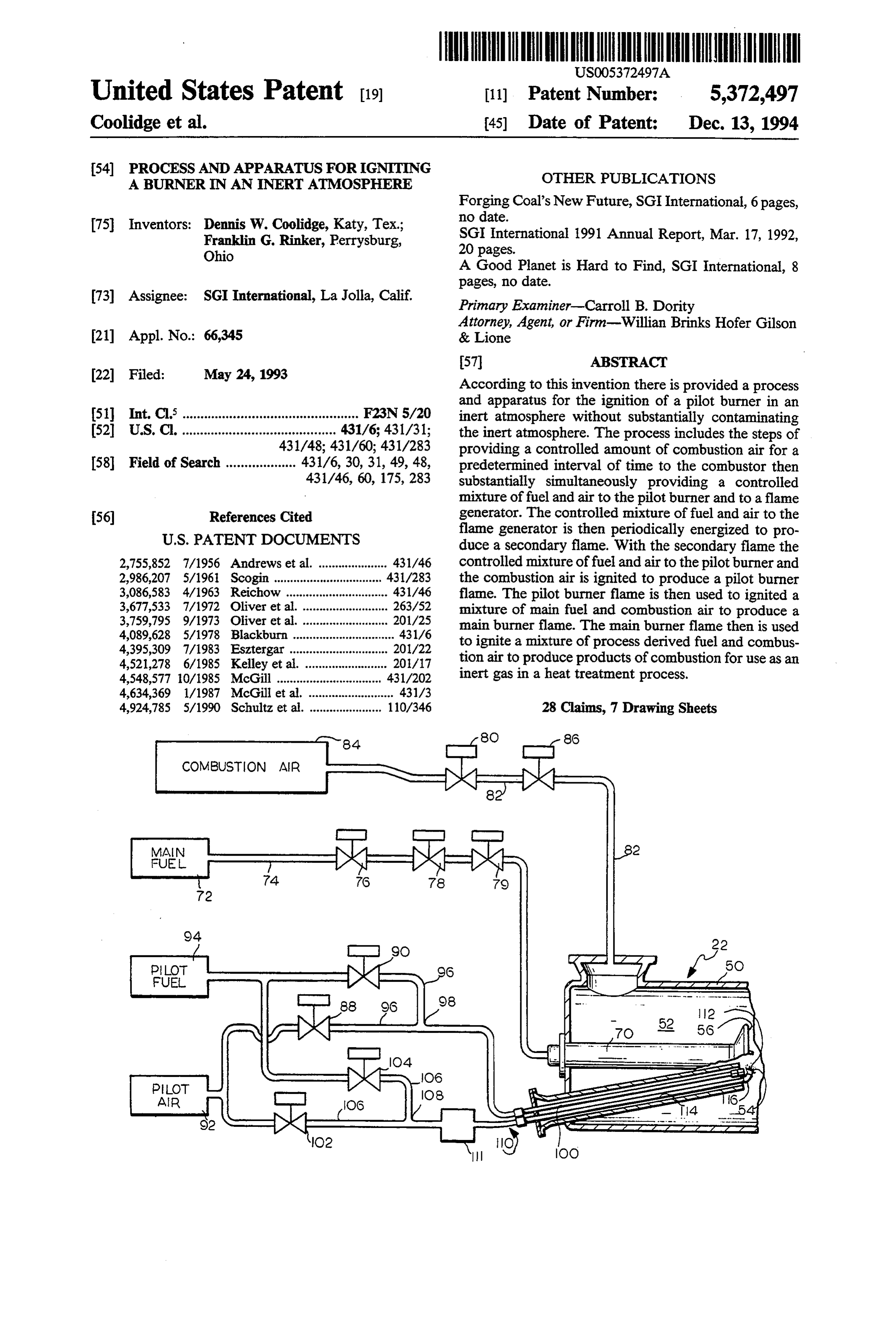
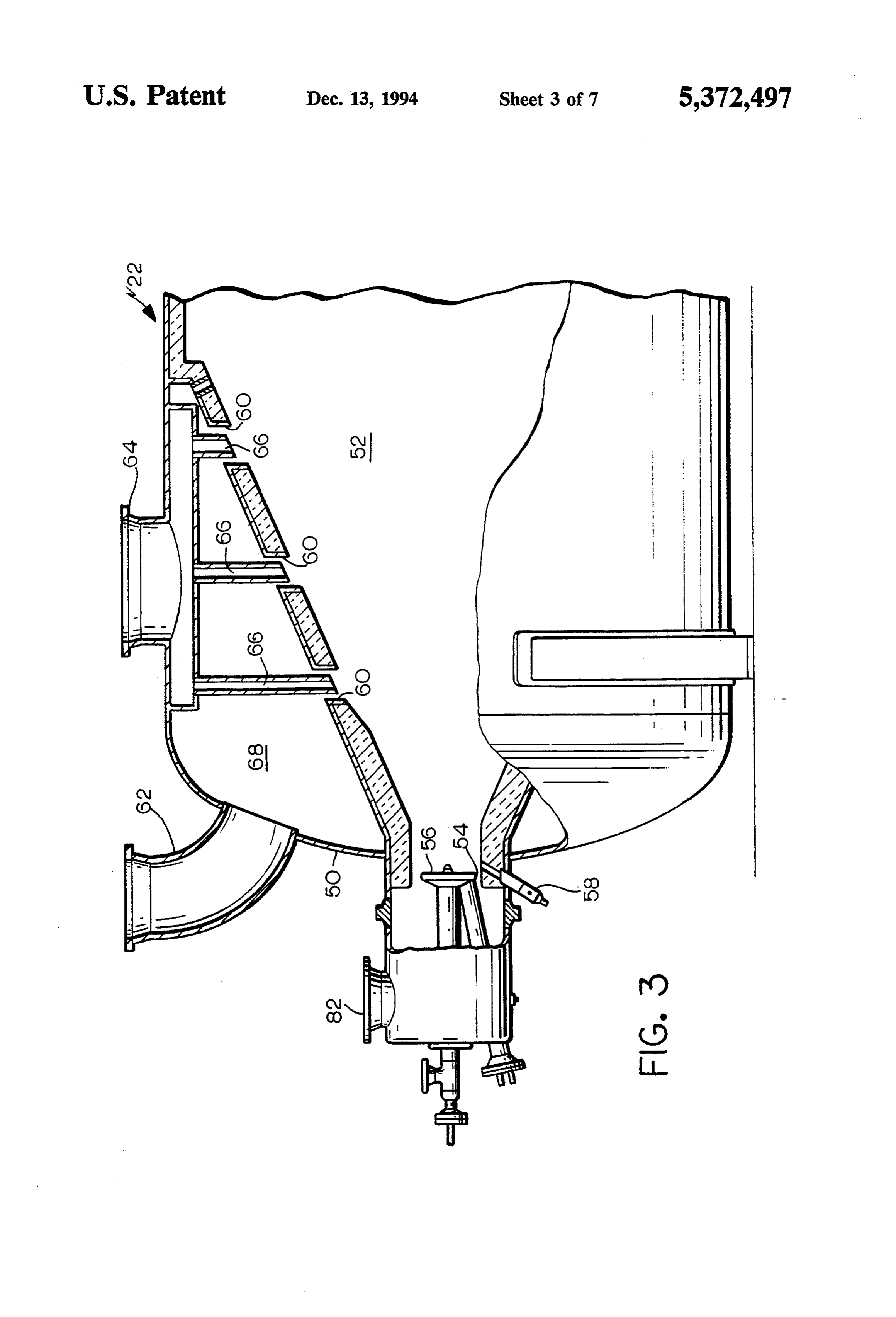
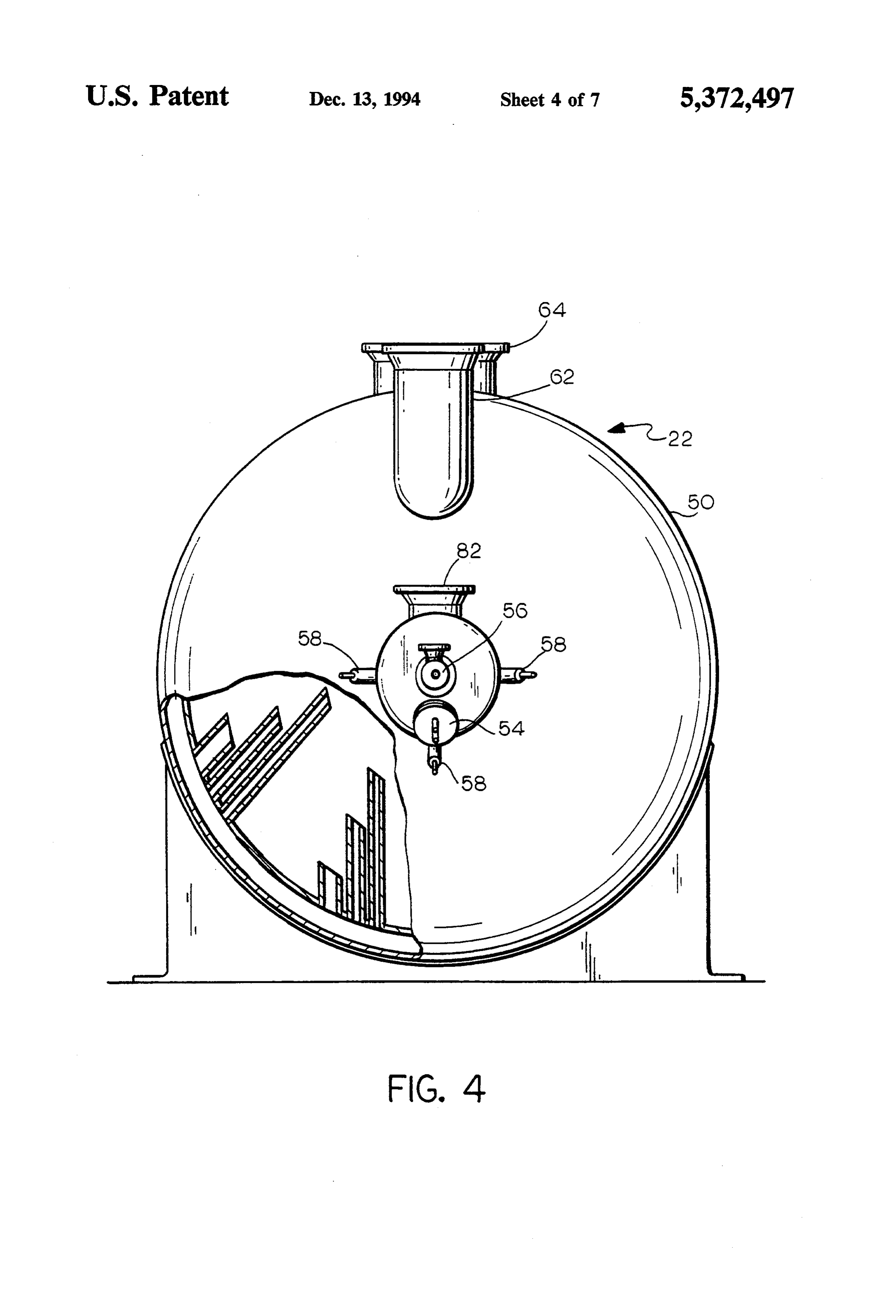
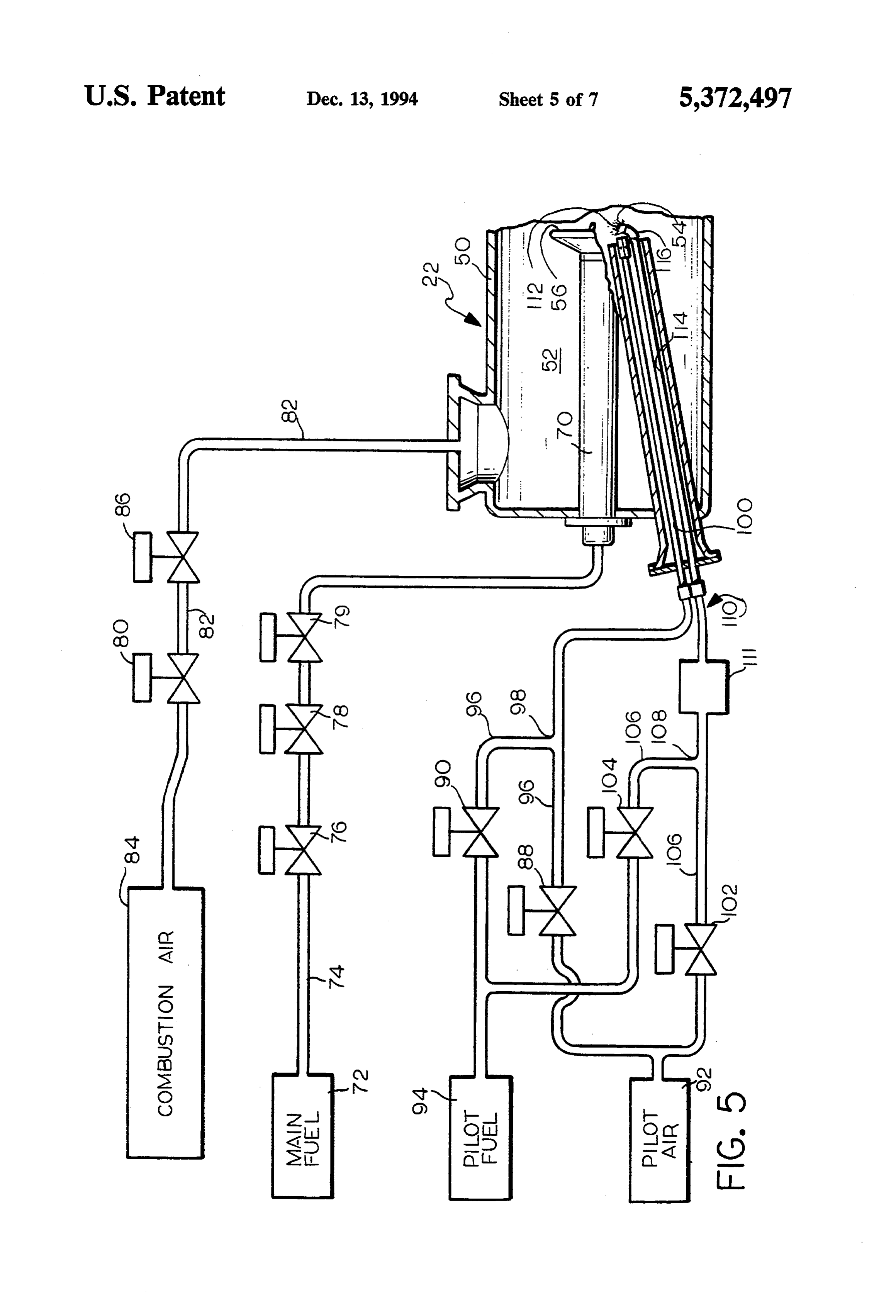
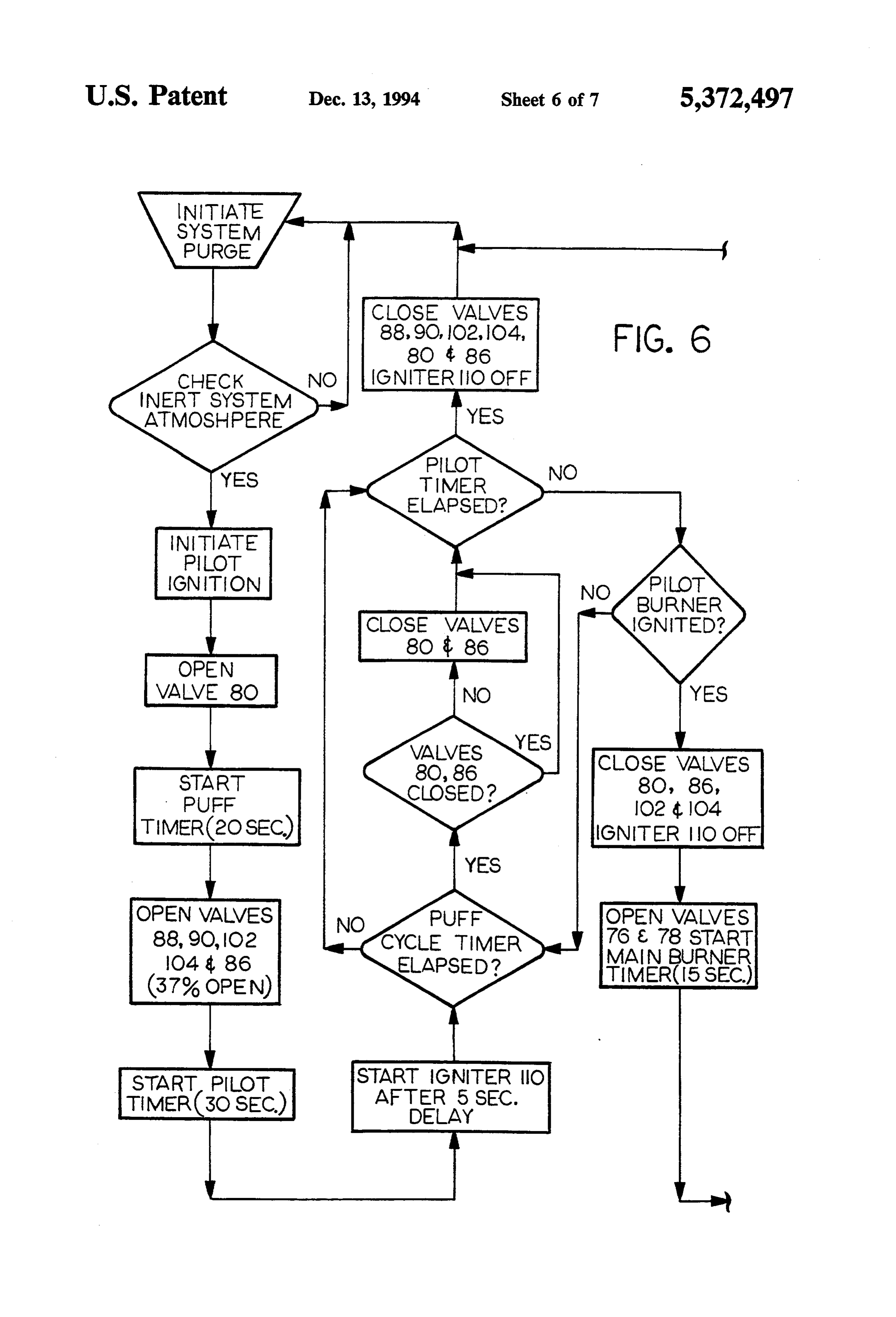
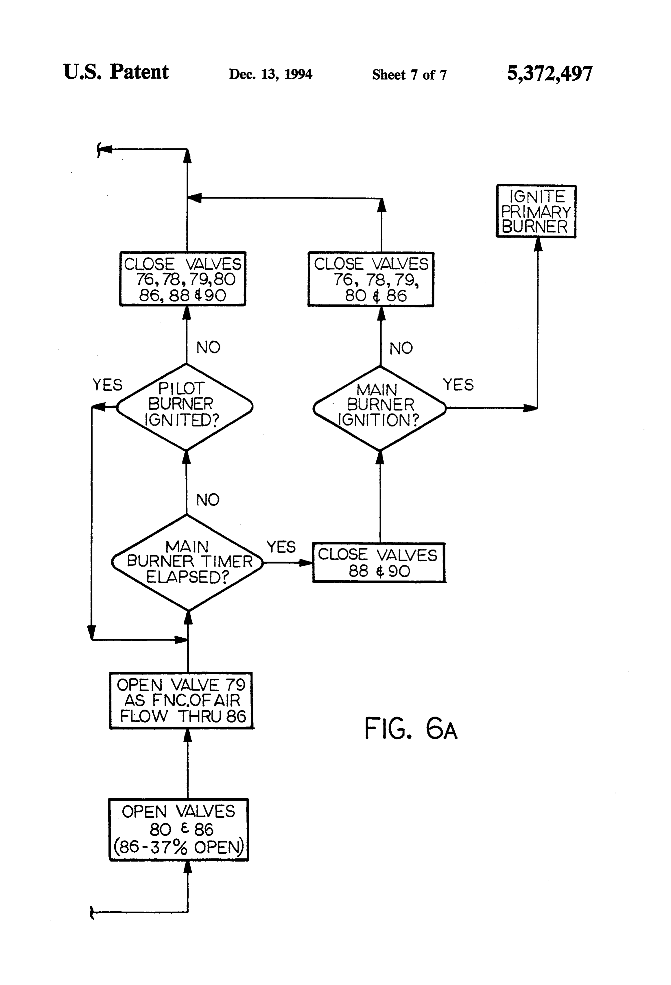
Further features and other aspects and advantages of suitable manner. For efficiency, the coal may be pre this invention will become clear from the following pared by washing, crushing and classifying to provide detailed description made with reference to the draw coal of suitable quality, quantity and particle size. ings in which: The process of the system 10 generally includes con FIG. 1 is a diagrammatic presentation of a pyrolysis 35 veying the coal to a coal dryer feed hopper 20 and dryer circuit for heat treating combustible materials; 18. The dryer 18 heats the coal to reduce the moisture FIG. 2 is a diagrammatic presentation of a dryer content of the coal. The temperature of the coal is con circuit for heat treating combustible materials; trolled below approximately 600 degrees fahrenheit so FIG. 3 is a partial cross-sectional side view of a com that no significant amounts of methane and/or carbon bustor shown in FIGS. 1 and 2 including a pilot system monoxide are released from the coal. The dry coal is in accordance with the present invention; then conveyed to a pyrolyzer 16 where the rate of heat FIG. 4 is an end view of the combustor of FIG. 3; ing of the solids and residence time are controlled to FIG. 5 is a diagrammatic representation of a burner achieve certain desired properties of the coal, e.g., system for the combustors of FIGS. 4 and 5; and lower relative sulphur content and higher relative car FIG. 6 is a flow chart of the pilot burner and main 45 bon content. During processing of the coal in the pyro burner ignition sequence. lyzer 16, all remaining free moisture is removed and a DESCRIPTION OF THE PREFERRED chemical reaction occurs resulting in the release of
EMBODIMENTS
volatile gaseous material and the formation of char. The processed coal or char is then removed from the pyro
Referring to the drawings, wherein like reference 50 lyzer, quenched, cooled and transferred for storage characters represent like elements, FIGS. 1 and 2 depict and/or conveyed for combustion in combustors as re a system 10 for recycling of an oxygen deficient gas quired as a process derived fuel.
stream used in the heat treatment of combustible materi As previously described, the pyrolyzer 16 and dryer als such as gas permeable, solid carbonaceous materials. 18 may be any suitable bulk solid heat transfer device The system 10 comprises, in combination, a drying 55 including either a rotary grate, horizontal grate, sliding process 12 and a mild gasification process 14 for heat grate or fluidized bed for convective heat transfer. The treatment of combustible materials utilizing a recycled pyrolyzer 16 may be of any type known in the art such oxygen deficient gas stream. Although the present in as a batch type pyrolyzing furnace or a continuous type vention will be described in connection with the igni pyrolyzing furnace. Batch type pyrolyzing furnaces are tion of a burner used for generating an oxygen deficient essentially Box type furnaces and are distinguished by gas stream used in the heat treatment of combustible the types of drive mechanisms used to transfer the coal materials it will be appreciated that the present inven to be pyrolyzed into and out of the furnace. In so far as tion may find application in the ignition of most any continuous type pyrolyzing furnaces are concerned, burner in an inert atmosphere where the inert nature of there are essentially three types of furnaces. One of the the atmosphere is to be maintained. 65 most common is a rotary kiln pyrolyzer which includes In considering FIGS. 1-6, it will be appreciated that a horizontal rotating cylinder with the coal material to for purposes of clarity some of the details of construc be heated tumbled on the inside. A helical auger is typi tion have not been provided in view of such details cally installed on the kiln's inside diameter thereby pro
Page 11
viding a means for transporting the coal material the pilot burner assembly 54 is defined as the "puff through the furnace. Another type of continuous pyro cycle'. In addition to regulating the amount of combus lyzer includes a vertical shaft and sliding bed furnace tion air introduced into the combustor 22 or 24, the where coal is fed at the top of a cylindrical shaft and the second valve means precisely sequences the introduc coal is discharged at the bottom. Various bustle and tion of "puff' air in a predetermined pattern to coincide tuyere arrangements are employed to treat the descend with the flow of pilot fuel and pilot air to the pilot ing load through the furnace as a continuous fluidized burner assembly 54 and igniter 111, as will be explained bed. A third type of continuous pyrolyzer is a rotary in more detail herein.
hearth. A rotary hearth has an annular shaped hearth In a preferred embodiment, the second combustion rotating in a stationary furnace chamber and coal is 10 air control valve 86 is a 12 inch diameter butterfly type continually fed into a cold zone. A stationary spreader control valve approximately 37% open for introducing distributes the coal uniformly in a radial direction as the combustion air into a combustor 22 or 24 of approxi hearth rotates under the spreader. For a more detailed mately 3,000 ft3 in size. However, it will be appreciated discussion of furnaces useful in pyrolysis, reference is that the second combustion air control valve 86 opening made to U.S. Pat. No. 4,924,785, incorporated herein by 15 may be adjusted as required to supply a controlled reference. amount of air ("puff air”) in the immediate vicinity of The inert gas utilized for drying and pyrolysis of the the end of the pilot burner assembly 54 just sufficient for coal material is produced by a first combustor 22 and a ignition of the pilot burner assembly yet maintain the second combustor 24. The combustors 22 and 24 are of inert atmosphere within the combustor 22 or 24 as de similar construction and therefore only one combustor 20 termined by the flow rates of the fuel, air, valve size, will be described in detail. and combustor size.
As shown in FIGS. 3 and 4, the combustor 22 or 24 Referring to FIGS. 5 and 6, as is well known in the is generally of a cylindrical shape having outer walls 50 art, for safety reasons, during start-up of the combustor made of most any suitable material to withstand high 22 or 24, nitrogen is supplied to purge the system 10 and temperature and the forces of combustion. The combus 25 create an inert atmosphere within the combustor. Once tor 22 or 24 includes an inner chamber 52 having a an inert atmosphere is established throughout the sys frustoconical shape formed of a suitable refractory ma tem 10, the pilot burner assembly 54 of each of the terial and a forward end housing containing a pilot combustors is ignited (FIGS. 3-6).
burner assembly 54 and main burner assembly 56. Flame Ignition of the pilot burner assembly 54 is initiated by sensor ports containing flame sensors 58 are positioned 30 introduction of the "puff cycle'. The first combustion about the periphery of the housing to detect combus air blocking valve 80 is energized to the open position to tion. The flame sensors 58 are of a design well known in allow air to flow to the second combustion air control the art such as ultraviolet (UV) radiation sensors and valve 86. Once the first combustion air blocking valve the like. 80 is open the second combustion air control valve 86 is Formed about the periphery of the inner chamber 52 35 energized in a partially open position. In a preferred are a plurality of spaced openings 60. Primary air and embodiment, the second combustion air control valve primary fuel, as further described herein, are introduced 86 is energized to an approximately 37% open position. to the combustor 22 or 24 through primary air inlet 62 The first combustion air blocking valve 80 and second and primary fuel inlet 64. The primary fuel passes combustion air control valve 86 permit the controlled through the primary fuel inlet 64 and through a bank of 40 introduction of "puff' air into the combustor 22 or 24 tubes 66 (for example, 3 rows of 8 tubes) spaced about for a predetermined period of time or until ignition of the periphery of the combustor. The tubes 66 are of the pilot burner assembly 54 is established, whichever is varying diameter and length for dispersing the primary the first to occur.
fuel within the inner chamber 52. The primary air is As the "puff air is introduced to the combustor 22 or introduced through primary air inlet 62 into a chamber 45 24, air and fuel from the pilot fuel source 94 and pilot air 68 formed between the frustoconical inner chamber 52 source 92 are simultaneously introduced to the pilot and walls 50 of the combustor. The primary air flows burner assembly 54 and a pilot timer interval sequence is through openings 60 and intermixes with the primary initiated. As shown in FIG. 5, air and fuel from the pilot fuel within the inner chamber 52. Combustors suitable air source 92 and pilot fuel source 94 are simultaneously for use in the present invention may be obtained from 50 selectively introduced at ignitable proportions through John Zink, Tulsa, Okla. and Peabody Engineering, a third valve means having a first pilot air blocking Stamford, Conn. valve 88 and a second pilot fuel blocking valve 90 con The pilot burner assembly 54 is of the direct burner nected by conduit 96 to a mixing tee 98 for introduction type wherein the fuel and oxidizer are mixed at the of a mixture of pilot fuel and pilot air to pilot tube 100 point of ignition. As shown in FIGS. 3-5, the pilot 55 of the pilot burner assembly 54. Similarly, air and fuel burner assembly 54 in accordance with the present from the pilot air source 92 and pilot fuel source 94 are invention includes a second valve means for selectively simultaneously selectively introduced at ignitable pro introducing a controlled amount of combustion air to portions through a fourth valve means including flame the combustor 22 or 24. As shown in FIG. 5, the second air generator blocking valve 102 and flame fuel genera valve means includes a first combustion air blocking tor blocking valve 104 and conduit 106 to a mixing tee valve 80 connected by conduit 82 to a source of com 108. From the mixing tee 108 the mixture of air and fuel bustion air 84 and a second combustion air control valve flows to a flame generator 110 where the mixture is 86 downstream of the first combustion air blocking ignited or energized at predetermined intervals to pro valve for introduction of a controlled amount of com duce a secondary flame within the combustor 22 or 24 bustion air within the combustor 22 or 24 in the immedi 65 adjacent the end of the pilot tube 100. ate vicinity of the end of the pilot burner assembly 54. As shown in FIG. 5, the flame generator 110 includes The selective introduction of a controlled amount of an igniter 111 positioned external of the combustor 22 combustion air in the immediate vicinity of the end of or 24 for ease of access and to isolate the igniter from
Page 12
the high temperature formed within the combustor and within the combustor 22 or 24. The combustion of the a firing tube 114 internal of the combustor. The igniter mixture of combustion air and main fuel of the main 110 may be, for example, of an electric spark type, hot burner 56 initially produces the high sensible heat for surface type, flame type or shock wave type. The ig use in the system 10. The first pilot air blocking valve 88 niter 110 raises the mixture of fuel and air to the ignition and the second pilot fuel blocking valve 90 remain open temperature to produce a secondary flame 112. In a for a period of approximately 15 seconds as determined preferred embodiment, an electric spark igniter 110 of a from the period of time that the first main fuel blocking type known in the art provides 12,000 volts to ignite the valve 76 and second main fuel blocking valve 78 are mixture of pilot fuel, pilot air and combustion air ap opened. After the 15 second period the flame sensors 58 proximately 5 seconds after opening of the pilot fuel 10 scan to determine if the mixture of main fuel and com blocking valve 90, air blocking valves 88, 80 and air bustion air within the main burner tube 70 is ignited. If control valve 86 for about a 0.1 second pulse and at 5 the main burner assembly 56 is not ignited then the first second intervals thereafter for a total elapsed time of 25 main fuel blocking valve 76, second main fuel blocking seconds. Once the secondary flame 112 ignites the mix valve 78, third main fuel control valve 79, first combus ture of pilot fuel, pilot air and combustion air as deter 15 tion air blocking valve 80 and second combustion air mined by the flame sensors, the flame generator air control valve 86 are closed and the burner ignition blocking valve 102, flame generator fuel blocking valve sequence is reinitiated. During the above described 15 104 and fourth valve means are closed and the igniter second period, the flame sensors 58 also continue to 111 is de-energized. However, if after 25 seconds the scan for a flame within the pilot burner assembly 54. If pilot flame is not ignited by the secondary flame, the 20 at any time no flame is detected within the combustor flame generator air valve 102 and flame generator fuel 22 or 24, the first main fuel blocking valve 76, second valve 104 and the first pilot air valve 88 and second pilot main fuel blocking valve 78, third main fuel control fuel valve 104 are de-energized and closed. The process valve 79, first combustion air blocking valve 80, second of igniting the pilot flame may be reinitiated manually combustion air control valve 86, first pilot air blocking after inspection of the combustors 22 and 24. 25 valve 88 and the second pilot fuel blocking valve 90 are As shown in FIG. 5, the firing tube 114 in communi closed and the ignition sequence must be repeated. cation with the igniter 111 extends within the combus The pilot burner system in accordance with the pres tor 22 or 24 parallel to the pilot tube 100 for introduc ent invention must mix the fuel (e.g., methane), and tion of the secondary flame 112 adjacent the end of the oxidizing agent (e.g., combustion air), in proportions pilot tube. To improve the draft of the secondary flame 30 that are within the limits of flammability for ignition 112 a cowl 116 is provided on the tip of the firing tube and steady combustion without substantially changing 114. The cowl 116 directs the secondary flame 112 the inert nature of the gas atmosphere within the system toward the end of the pilot tube 100, thereby concen 10. Furthermore, the fuel and combustion air must be trating the effects of the secondary flame on the mixture supplied at rates that allow complete combustion with exiting from the pilot tube. 35 out any burning back into the fuel supply system or Upon ignition of the mixture exiting from the pilot carrying of the flame into a low temperature region tube 100 to form the pilot flame, the first main air block where the flame may be quenched. Ignition of the fuel ing valve 80, second main air control valve 86, flame and combustion air mixture is a function of temperature, generator air blocking valve 102, flame generator fuel pressure and the like as is well known in the art. blocking valve 104 are de-energized and closed and the The valves of the burner assemblies 54 and 56 are ignitor 111 is de-energized. The pilot burner assembly controlled by solenoids, in response to a control signal 54 produces a pilot flame for ignition of a combustible from a programmable logic controller of conventional mixture of combustion air and main fuel of a main design such as an Allen Bradley programmable logic burner assembly 56 to initially produce the high sensible controller, not shown, as determined by the operation heat for use in the system 10. 45 of the valve sequence previously described and burner The main burner assembly 56 includes a burner tube ignition condition as determined by the flame sensors 70 projecting within the combustor 22 or 24 to approxi 58.
mately the forward end of the inner chamber 52 for The pilot burner assembly 54 in accordance with the introduction of main fuel into the combustor. The main present invention prevents the contamination of the fuel passes from a main fuel source 72 through a first 50 inert atmosphere within the system 10 by intermittently valve means including a conduit 74, first main fuel providing controlled bursts or "puffs' of air above that blocking valve 76, second main fuel blocking valve 78, required for the theoretical combustion of the pilot fuel and third main fuel control valve 79 and main burner to enable the pilot burner to ignite. The pilot burners tube 70 to inner chamber 52 of the combustor 22 or 24. produce products of combustion, low in oxygen, from After the first main air blocking valve 80, second main 55 any one of the combustors 22 or 24 from the very onset air control valve 86, flame generator air blocking valve of the combustor ignition thereby avoiding the condi 102, flame generator fuel blocking valve 104 are de tion of excess unburned fuel or excess oxygen flowing energized and closed and the ignitor 111 is de-energized from the combustors during periods of ignition. the first main fuel blocking valve 76 and second main For example, a pilot burner assembly 54 in accor fuel blocking valve 78 are opened. Next, the first main dance with the present invention provides products of air blocking valve 80 and second main air control valve combustion within the combustor containing no more 86 are opened (second main air control valve 86 opened than approximately 0.5% oxygen as measured at the exit 37%) and then the third main fuel control valve 79 is of the combustor for the pyrolyzer circuit and no more opened proportionally with the rate of combustion air than approximately 1.0% oxygen as measured at the exit flow through conduit 82. The fuel introduced from the 65 of the combustor for the dryer circuit. main fuel source 72 through the first valve means and During operation, combustion of the main fuel and combustion air from the second valve means form a combustion air and, as required recycled inert gas, pro combustible mixture for ignition of the main burner 56 ceeds within the combustion chamber of the combus
Page 13
tors 22 and 24 at a temperature between approximately The drying process 12 includes a second combustor 1550-2050 degrees fahrenheit, and preferably 24, a dryer 18 and, if desired, a scrubber 34. The second 1600-1950 degrees fahrenheit at near stoichiometric combustor 24 is substantially similar to the first combus conditions, thereby producing high sensible heat prod tor 22 in design and operation as described above to ucts of combustion containing carbon dioxide, carbon produce high sensible heat inert gas for drying the coal monoxide, water vapor, nitrous oxides and Sulphur material within the dryer. The products of combustion oxides. It will be appreciated that a combustion temper from the second combustor 24 are conveyed to the ature above 1550 degrees fahrenheit oxidizes potential dryer 18 to remove moisture from the coal, thereby air pollutants and below 1959 degrees fahrenheit avoids O producing a dry high heating value coal material. For the formation of excessive amounts of nitrogen oxides. drying of the coal, the ratio of inert gas to coal is 3.0-6.0 Further enhancement of the combustion process may by mass, and preferably 3.5 by mass. be achieved by mixing recycled inert gas exiting from It will be appreciated that the first and second com the pyrolyzer 16 with the fuel and air entering the first bustors 22 and 24 also act as internal flares for environ combustor 22. It will be appreciated that by recycling mental emission control following an unplanned shut low sensible heat inert gas and mixing the gas with the down with hydrocarbon vapors present in the dryer 18 fuel and air, hydrocarbon vapors, carbon monoxide and or pyrolyzer 16. The thermal inertia or stored energy in hydrogen sulfide are removed from the inert gas and the combustor refractories will serve as an auto-ignition fuel value is obtained from the recycled inert gas. In Source for the hydrocarbon vapors remaining in the addition, because inert gas is recycled, large volumes of 20 system. Auxiliary fuel and combustion air may also be economical high sensible heat inert gas may be pro provided on a contingency basis to thermally oxidize duced for both drying and pyrolysis than would other otherwise undesirable vapors within the inert gas prior wise be possible. to their release from the system 10. Recycled inert gas exiting from the pyrolyzer 16 is From the dryer 18 the vapor is treated to separate then mixed with the main fuel and combustion air and 25 solid particles from the low sensible heat vapor product acts to attemperate the combustion process to achieve exiting from the dryer within a separator 36 device of a the desired outlet temperature, products of combustion type well known in the art. The low sensible heat vapor chemistry and mass flow rate for subsequent introduc exiting from the separator 36 may then be either vented tion into a mixing tee 30 for mixing with additional low or recycled and mixed with the products of combustion sensible heat inert gas which bypasses the first combus 30 exiting from the second combustor 24. tor 22. The controlled products of combustion from the The second combustor 24 is continually monitored first combustor 22 are then conveyed to the mixing tee for the purpose of increasing or decreasing the inert gas 30 and mixed with low sensible heat recycled inert gas content of the products of combustion from the second from the pyrolyzer 16 to form high sensible heat inert combustor. More particularly, the mass flow and the gas having a desired on-gas temperature. The first com 35 temperature of inert gas and air streams entering and bustor 22 is continually monitored for the purpose of products of combustion exiting the second combustor increasing or decreasing the amount of recycled inert are monitored to maintain minimum and maximum gas to be mixed with the products of combustion. More combustor temperature requirements as previously de particularly, the mass flow and the temperature of recy scribed.
cled inert gas, fuel and air streams entering and the It is to be understood that although the present inven products of combustion exiting the first combustor 22 tion has been described with reference to the ignition of are monitored to maintain minimum and maximum a pilot burner for the heat treatment of combustible combustor temperature requirements as previously de materials such as a solid carbonaceous material (e.g., scribed. The resulting products of combustion exiting coal), it will be appreciated by those skilled in the art the first combustor 22, high in sensible heat and low in 45 that the present invention may find application as a combustible and/or oxygen are subsequently utilized means for igniting a flame in most any inert atmosphere for thermal processing of reactive coal particles within to maintain the inert nature of the atmosphere. the pyrolyzer 16. The publications, documents, patents and patent ap In the pyrolyzer 16, sensible heat is transferred from plications referred to herein are hereby incorporated by the high sensible heat inert gas to the coal material 50 reference.
thereby separating from the coal material volatile mat Having described presently preferred embodiments ter. The volatile matter is the portion of the coal mate of the invention, it is to be understood that it may be rial which when heated in the absence of air is liberated otherwise embodied within the scope of the appended as gases and vapors. It will be appreciated that volatile claims.
matter does not exist by itself in coal, except for a small 55 What is claimed is:
amount of methane, but results from thermal decompo 1. A process for igniting a main burner of a combus sition of the coal material. For pyrolysis of the coal, the tor to produce a main burner flame within a closed ratio inert gas to coal is 1.5-2.5 by mass and preferably system containing an inert atmosphere without substan 2.0 by mass. tially contaminating the inert atmosphere, the process From the pyrolyzer 16 the admixed low sensible heat comprising the steps of:
inert gas, volatile matter and solid particles are sepa a) purging the combustor to establish an inert atmo rated in a separator collection device 32 of a type well sphere within the combustor; known in the art. The solid particles and volatile matter b) supplying a controlled amount of combustion air may then be transferred for storage and the low sensible for a predetermined interval of time to said com heat inert gas recycled to either the first combustor for 65 bustor;
renewal and/or the drying process 12 and/or mixing c) substantially simultaneously supplying a controlled with the products of combustion from the first combus mixture of fuel and air to a pilot burner and to a tOt. flame generator;
Page 14
d) intermittently igniting the controlled mixture of 13. The process of claim 8 wherein no more than fuel and air to the flame generator to produce a approximately 1.0% oxygen is present at the combustor secondary flame; exit.
e) igniting the controlled mixture of fuel and air to the 14. A process for igniting a primary burner of a com pilot burner and the combustion air with the sec bustor to produce a primary burner flame within a ondary flame to produce a pilot burner flame; closed system containing an inert atmosphere without substantially contaminating the inert atmosphere, the f) supplying a controlled amount of fuel and air to the process comprising the steps of:
main burner within the combustor; and g) igniting the controlled amount of fuel and air to the 10 a) sphere purging the combustor to establish an inert atmo within the combustor;
main burner with the pilot burner flame to produce a main burner flame. b) supplying a controlled amount of combustion air 2. The process of claim 1 further comprising the step for a predetermined interval of time to said com of terminating the supply of fuel and air to the flame bustor;
generator after ignition of the pilot burner. c) substantially simultaneously supplying a controlled 3. The process of claim 2 further comprising the step 15 mixture of fuel and air to a pilot burner and to a of terminating the supply of fuel and air to the pilot flame generator;
burner after ignition of the main burner. d) periodically igniting the controlled mixture of fuel 4. The process of claim 3 wherein the controlled and air to the flame generator to produce a second mixture of fuel and air to the flame generator is supplied 20 e) ary flame;
igniting the controlled mixture of fuel and air to the periodically for a selected period of time after supplying pilot burner and the combustion air with the sec a controlled mixture of fuel and air to a pilot burner ondary flame to produce a pilot burner flame; until ignition of the pilot flame or lapse of the selected f) supplying a controlled amount of fuel and air to the period of time. main burner within the combustor; 5. The process of claim 4 wherein the flame generator 25 g) igniting the controlled amount of fuel and air to the is activated approximately 5 seconds after supplying a main burner with the pilot burner flame to produce controlled mixture of fuel and air to a pilot burner and a main burner flame;
at 5 second intervals thereafter, h) supplying a controlled amount of fuel and air to the 6. The process of claim 5 wherein the selected period primary burner within the combustor; of time is approximately 25 seconds. 30 i) igniting the controlled amount of fuel and air to the 7. The process of claim 1 wherein the controlled primary burner with the main burner flame to pro amount of combustion air is supplied for a predeter duce a primary burner flame. mined interval of time to said combustor in the immedi 15. The process of claim 14 further comprising the ate vicinity of the pilot burner. step of terminating the supply of fuel and air to the 8. A process for igniting a pilot burner assembly of a 35 flame generator after ignition of the pilot burner. combustor to produce a pilot burner flame within a 16. The process of claim 15 further comprising the closed system containing an inert atmosphere without step of terminating the supply of fuel and air to the pilot substantially contaminating the inert atmosphere, the burner after ignition of the main burner. process comprising the steps of: 17. The process of claim 16 wherein the controlled a) purging the combustor to establish an inert atmo mixture of fuel and air to the flame generator is acti sphere within the combustor; vated periodically for a selected period of time after b) supplying a controlled amount of combustion air supplying a controlled mixture of fuel and air to a pilot for a predetermined interval of time to said com burner until ignition of the pilot flame or lapse of the bustor; selected period of time.
c) substantially simultaneously supplying a controlled 45 18. The process of claim 17 wherein the flame genera mixture of fuel and air to the pilot burner and to a tor is energized approximately 5 seconds after supplying flame generator; a controlled mixture of fuel and air to a pilot burner and d) periodically igniting the controlled mixture of fuel at 5 second intervals thereafter.
and air to the flame generator to produce a second 19. The process of claim 18 wherein the selected ary flame; and 50 period of time is approximately 25 seconds. e) igniting the controlled mixture of fuel and air to the 20. The process of claim 19 wherein the controlled pilot burner and the combustion with the second amount of combustion air is supplied for a predeter ary flame to produce a pilot burner flame. mined interval of time to said combustor in the immedi 9. The process of claim 8 further comprising the step ate vicinity of the pilot burner.
of terminating the supply of fuel and air to the flame 55 21. An apparatus for igniting a pilot burner flame of a generator after ignition of the pilot burner. pilot burner assembly of a combustor within a closed 10. The process of claim 9 wherein the controlled system containing an inert atmosphere, the apparatus mixture of fuel and air to the flame generator is acti comprising:
vated periodically for a selected period of time after a) a second valve means for selectively introducing a supplying a controlled mixture of fuel and air to a pilot controlled amount of combustion air for a first burner until ignition of the pilot flame or lapse of the predetermined period of time to said combustor; selected period of time. b) a third valve means for selectively introducing fuel 11. The process of claim 10 wherein the flame genera and air for a second predetermined period of time tor is activated approximately 5 seconds after supplying to a pilot burner including a pilot tube extending a controlled mixture of fuel and air to a pilot burner and within said combustor;
at 5 second intervals thereafter. c) a fourth valve means for selectively introducing 12. The process of claim 11 wherein the selected fuel and air to a flame generator substantially si period of time is approximately 25 seconds. multaneously with the introduction of fuel and air
Page 15
to said pilot burner, said flame generator having an and air is supplied to a pilot burner and at 5 second igniter positioned external of said combustor and a intervals thereafter.
firing tube extending within said combustor paral 24. The apparatus of claim 23 wherein said selected lel to said pilot burner, said igniter including means period of time is approximately 25 seconds. for intermittently igniting said fuel and air to pro 5 25. The apparatus of claim 21 including means for duce a secondary flame within said firing tube supplying said controlled amount of combustion air for internal of said combustor thereby igniting said a predetermined interval of time to said combustor in controlled mixture of fuel, air and combustion air the immediate vicinity of said pilot burner. within said combustor to produce a pilot flame 26. The apparatus of claim 25 wherein said firing tube
includes a cowl for directing said secondary flame d) a means for controlling the operation of said sec toward an end of said pilot tube. ond valve means, said third valve means and said 27. The apparatus of claim 21 wherein said second fourth valve means to provide a combustible mix ture of fuel, air and combustion air within said valve second means includes a first combustion air valve and a combustion air valve for introducing a con combustor in the vicinity of said igniter and said 15 trolled amount of combustion air within said combustor pilot tube. in the immediate vicinity of said pilot burner assembly. 22. The apparatus of claim 21 including means wherein said flame generator ignites said controlled 28. The apparatus of claim 27 further comprising a mixture of fuel and air periodically for a selected period first valve means for supplying a controlled amount of of time until ignition of said pilot flame or lapse of said 20 fuel and air to a main burner within said combustor, selected period of time. whereby said controlled amount of fuel and air to said 23. The apparatus of claim 22 including means main burner is ignited by said pilot burner flame to wherein said flame generator is activated approximately produce a main burner flane. r k 5 seconds after a supply of controlled mixture of fuel
Provenance
- Collection
- Cited prior art
- Original PDF
- patentimages.storage.googleapis.com →
- Filed
- 1993-05-24
- Pages
- 15
- Method
- pdftotext (the PDF's own text layer) + pdftoppm 300dpi page scans
- Source
- Google Patents bibliographic record
- Granted
- 1994-12-13
- Inventors
- Dennis W. Coolidge; Franklin G. Rinker; SGI International Inc
- Transcribed from
- patentimages.storage.googleapis.com →