patent · US4234257
Flame photometric detector adapted for use in hydrocarbon streams
18 November 1980
Page 1 — bibliographic record
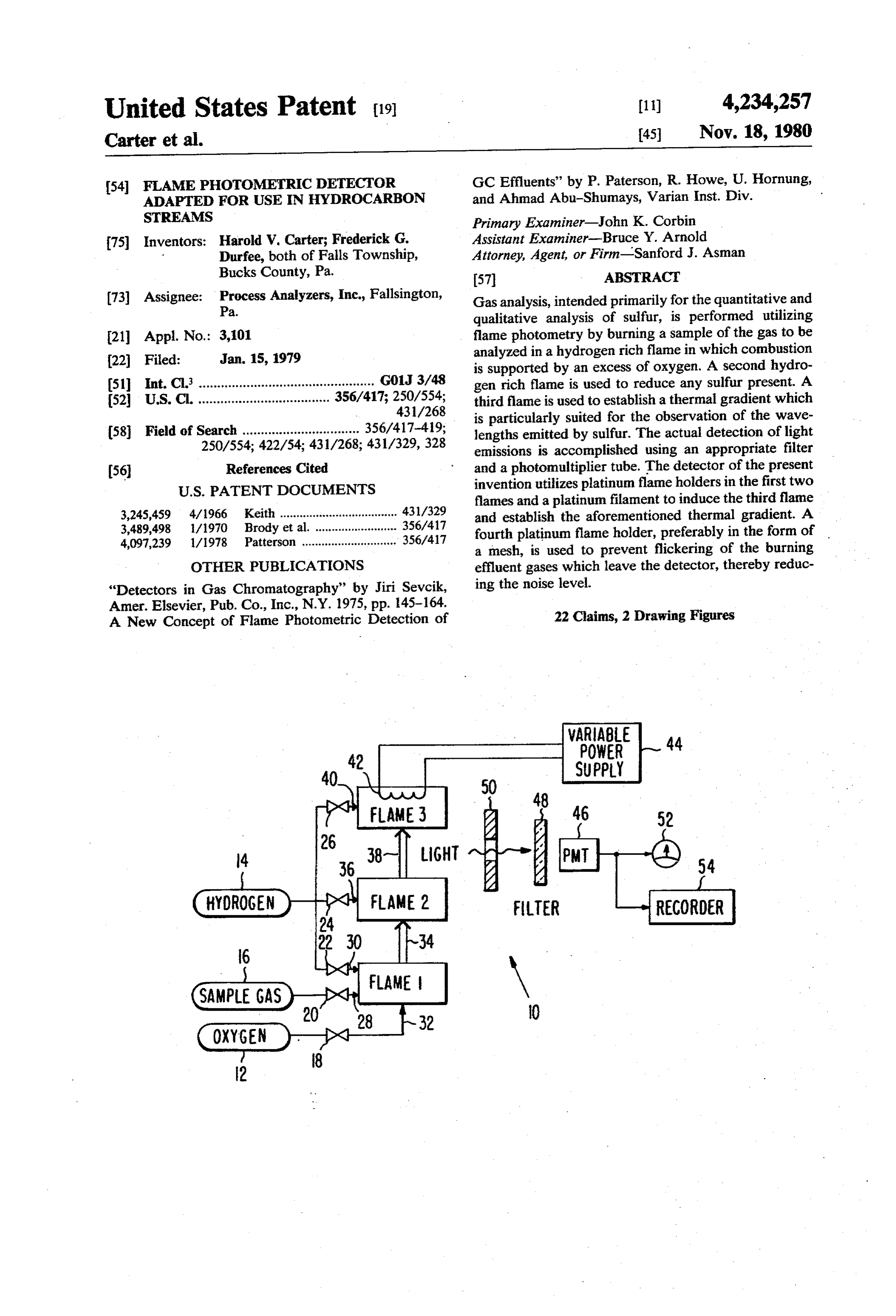
United States Patent (19) 11) 4,234,257 Carter et al. 45 Nov. 18, 1980
54 FLAME PHOTOMETRIC DETECTOR GC Effluents” by P. Paterson, R. Howe, U. Hornung, ADAPTED FOR USE IN HYDROCARBON and Ahmad Abu-Shumays, Varian Inst. Div. STREAMS Primary Examiner-John K. Corbin 75 Inventors: Harold V. Carter; Frederick G. Assistant Examiner-Bruce Y. Arnold Durfee, both of Falls Township, Attorney, Agent, or Firm-Sanford J. Asman
Bucks County, Pa. 57 ABSTRACT 73) Assignee: Process Analyzers, Inc., Fallsington, Gas analysis, intended primarily for the quantitative and Pa. qualitative analysis of sulfur, is performed utilizing 21 Appl. No.: 3,101 flame photometry by burning a sample of the gas to be 22 Filed: Jan. 15, 1979 analyzed in a hydrogen rich flame in which combustion is supported by an excess of oxygen. A second hydro 51 int. Cl. ................................................ GOJ 3/48 gen rich flame is used to reduce any sulfur present. A 52 U.S. C. .................................... 356/417; 250/554; third flame is used to establish a thermal gradient which 431/268 is particularly suited for the observation of the wave 58) Field of Search ................................ 356/417-419; lengths emitted by sulfur. The actual detection of light 250/554; 422/54; 431/268; 431/329,328 emissions is accomplished using an appropriate filter (56) References Cited and a photomultiplier tube. The detector of the present
flames and a platinum filament to induce the third flame 3,245,459 4/1966 Keith .................................... 431/329 and establish the aforementioned thermal gradient. A 3,489,498 1/1970 Brody et al. ......................... 356/417 fourth platinum flame holder, preferably in the form of 4,097,239 1/1978 Patterson ............................. 356/417 a mesh, is used to prevent flickering of the burning OTHER PUBLICATIONS effluent gases which leave the detector, thereby reduc "Detectors in Gas Chromatography” by Jiri Sevcik, ing the noise level.
Amer. Elsevier, Pub.Co., Inc., N.Y. 1975, pp. 145-164. 22 Claims, 2 Drawing Figures A New Concept of Flame Photometric Detection of
POWER
SUPPLY
Page 2
Drawing sheet — no readable text.
Page 3
The emission from the excited molecules decreases
FLAME PHOTOMETRIC DETECTOR ADAPTED exponentially with increases in the concentration of the FOR USE IN HYDROCARBON STREAMS organic substance. Hydrocarbons substantially decrease the emission of sulfur,
The present invention relates to a flame photometric 5 Many of the problems discussed herein regarding the detector and is particularly related to a flame photomet difficulty of detecting sulfur in hydrocarbon streams are ric detector adapted to detect sulfur in a hydrocarbon more fully discussed in "Detectors in Gas Chromatog Steam. raphy' by Jiri Sevcik, American Elsevier Publishing Heretofore, flame photometric detectors have been Company, Inc., New York (1975), pages 145-164, used for the detection of sulfur and phosphorus com O which book is incorporated herein by reference. pounds in gas streams. Such detectors have not been The present invention provides an improved flame successfully used for the detection of sulfur orphospho photometric detector for detecting the presence of sul rus when those elements are present in a hydrocarbon fur in a sample gas, which may be a hydrocarbon. In sample gas. In view of the fact that the presence of order to accomplish that result the flame photometric sulfur is extremely detrimental to many processes which 15 detector of the present invention employs three flames. employ hydrocarbon streams, such as processes which The first flame is used to oxidize the sample gas in a utilize a nickel catalyst, the ability to detect and mea hydrogen rich environment. The first flame is intended sure the sulfur content of a hydrocarbon stream is ex to fully burn any hydrocarbon present and to oxidize tremely important. Accordingly, hereafter all reference any sulfur which is present in the sample gas. A lean, i.e. will be limited to sulfur. However, such reference to 20 an oxygen rich, mixture is preferably used to accom sulfur should be construed to include other elements, plish that result.
such as phosphorus, or compounds thereof.
Flame photometric detectors used for the detection. in The second flame is used to reduce any sulfur present order that the sulfur goes. into the S2 state wherein it of sulfur operate by measuring the intensity of light will emitted at a particular wavelength in response to energy 25 ingly,emit light having a wavelength of 394 nm. Accord the second flame is rich in hydrogen, which gas added to excite the sulfur molecules. The excited mole cules return to their ground state via either emission of serves as a reducing agent. Devices. having two flames of the type described radiative energy or by non-radiative de-excitation with above have heretofore been known, and one such de another substance, such as by the so-called "quenching' reaction. 30 vice is shown in U.S. Pat. No. 3,489,498 issued to S. S. By monitoring appropriate wavelengths, representa Brody et al. on Jan. 13, 1970. The present invention tive of the emission characteristics of the element being differs from such prior devices in that it includes means investigated, the presence of that element can be deter for containing the first two flames. In the preferred mined qualitatively. Through the use of known calibra embodiment of the present invention, the means for tion references, the flame photometric detector can be 35 containing the flames comprises platinum (Pt) wires calibrated to provide accurate quantitative analysis. which act as flame holders. In addition, platinum acts as Sulfur in the S2 molecule exhibits a strong emission at a catalyst in a substantially stoichiometric mixture of 384 nm (3840 A) and at 394 nm (3940 A). Problems hydrogen and oxygen, to self-ignite the mixture thereby which have heretofore inhibited accurate detection of eliminating the need to provide additional means for sulfur include the light output from interfering groups, 40 igniting the mixture. Thus, the platinum flame holders i.e. light output having a strong emission at a wave simultaneously act as ignitors and flame holders for length close to that of sulfur, and the “quenching' reac accurately locating the flames and preventing them tion previously mentioned. In particular, the CN group from flickering. Accordingly, the flame photometric has an emission peak at 385 nm. Accordingly, the detec detector of the present invention does not experience tion of sulfur is particularly difficult when the combus 45 any flameout problems of the type heretofore experi tion products of the sample gas include members of the enced in the detectors of the prior art. CN group. Such gases as cyanogen (C2N2) are pro In addition to the platinum flame holders, the present duced when hydrocarbons are burned in air, which is invention employs a helical platinum filament located rich in nitrogen (N2). While the CN groups can be elimi over the second flame. The platinum filament, which nated by using oxygen rather than air to support com 50 bustion, thereby eliminating nitrogen from the stream, has not heretofore been employed in flame photometric detectors is heated by passing an electrical current the presence of the C-H groups in hydrocarbon therethrough streams have also hampered efforts to use flame pho third flame is incomprised order to produce the third flame. The of the remaining combustible tometry for the detection of sulfur in hydrocarbon materials which are present in the gas flow. The inven streams, because the C-H groups have strong emission 55 tors believe that a temperature gradient exists between peaks at 388.3 nm and at 390 nm.
In view of the spectral interference of hydrocarbons correctly setting the gas flow ratescanand the second and third flames which be adjusted by the current in the immediate vicinity of the sulfur emission, flame photometry could not heretofore be accurately em through the helical platinum filament. They believe that ployed with hydrocarbon streams unless the hydrocar 60 the thermal gradient provides optimal conditions for observing the sulfur emission.
bon was first separated by a gas chromatograph.
In addition, the "quenching' reaction, which is a Each of the three flames described is located within a non-radiative de-excitation process, significantly affects glass chimney which in turn is located within a light the detection mechanism in the flame photometric de tight box. As a result of the combined elements de tector. The "quenching' phenomenon reportedly re 65 scribed herein, the present invention provides a flame sults from molecules of organic substances absorbing photometric detector which is much more sensitive to the energy of excited molecules, resulting in a simulta sulfur in hydrocarbon streams than any detectors here neous change in their vibrational and rotational states. tofore known.
Page 4
IN THE DRAWINGS In the preferred embodiment of the invention, the filter 48 has a peak transmission centered at about 394
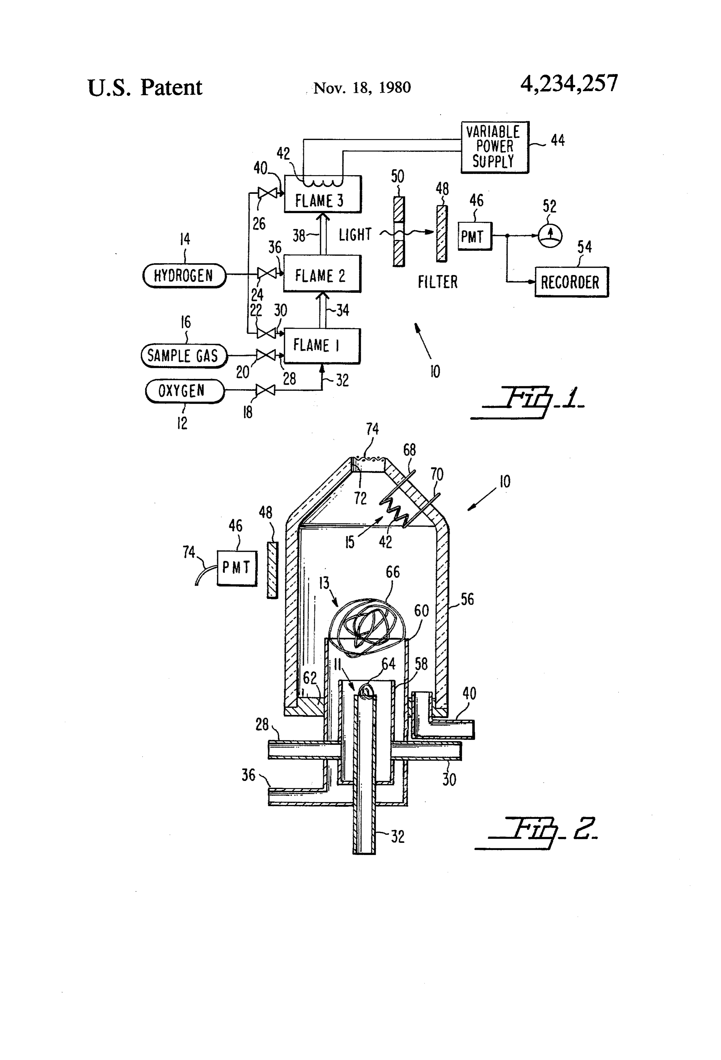
FIG. 1 is a diagrammatic illustration of the flame nm (3940 A). The pass band of the filter 48 lies between photometric detector of the present invention; and about 389 nm and 399 mm. Thus, the filter 48 is intended FIG. 2 is a cross-sectional view of the flame photo to prevent the photomultiplier tube 46 from receiving metric detector. light other than light which is emitted by sulfur. It is Referring now to FIG. 1, the flame photometric de preferable to include shields 50 in the detector 10 to tector 10 of the present invention is shown diagrammat shield the photomultiplier tube 46 from light given off ically. The detector 10 comprises supplies of oxygen gas directly by either Flame 2 or by Flame 3. The output of 12, hydrogen gas 14, and a sample gas 16, which sample 10 the photomultiplier tube 46 is preferably fed to a meter gas may comprise a hydrocarbon containing an un 52 and a permanent record is made on a suitable chart known amount of sulfur. A valve 18 controls the flow recorder 54.
rate of oxygen, and a valve 20 controls the flow rate of Referring now to FIG. 2, a cross-sectional view of the sample gas. In the preferred embodiment in the the flame photometric detector 10 of the present inven invention three valves 22, 24, 26 are used to control the 15 tion is shown. The detector 10 comprises a silica glass flow rate of hydrogen. envelope or chimney 56 which is open at the top and In the operation of the detector 10, the sample gas closed by a base 62 at the bottom. In the preferred flows from its supply 16 through a line 28, with its flow embodiment of the invention the base 62 is made of rate controlled by valve 20. Similarly, hydrogen flows 20 stainless steel. The burners 11, 13, 15 which contain from its supply 14 through a line 30, with its flow rate Flame 1, Flame 2, and Flame 3, respectively, are housed controlled by valve 22, and oxygen flows from its sup within the glass chimney 56. Entering the chimney 56 ply 12 through a line 32, with its flow rate controlled by through the base 62 is an oxygen line 32 which is com a valve 18. The hydrogen flowing through line 30 com prised of a stainless steel tube having a 1/16 inch outside bines with the sample gas flowing through line 28 and 25 diameter in the preferred embodiment of the invention. oxygen flowing through line 32 to produce Flame 1. In A second stainless steel tube 58 having an outside diam the preferred embodiment of the invention, the valves tion eter of inch in the preferred embodiment of the inven surrounds the oxygen line 32 and is concentric 18, 20, 22 are adjusted to provide a sample gas flow rate therewith.
through line 28 on the order of 1 ml/min., a hydrogen 30 open intoThe the sample gas line 28 and the hydrogen line inch diameter tube 58. Those lines 28, gas flow rate through line 30 of between about 2 and 5 30 30 enter the second tube 58 after passing through the ml/min. and an oxygen flow rate through line 32 suit walls of a third concentric stainless steel tube 60. In the able to provide an oxygen rich but substantially stoi preferred embodiment of the invention, the third stain chiometric mix at Flame 1. Flame 1 is intended to fully less steel tube 60 has an outside burn the sample gas and to oxidize any sulfur present in mately inch. While appropriate diameter of approxi seals and fittings are the sample gas. 35 required where the various tubes pass through one an The combustion products of Flame 1 (represented by other and where the base 62 joins the chimney 56, such the double arrow 34) flow upward through the detector seals and fittings would be obvious to those skilled in 10 and are combined with additional hydrogen pro the art. Accordingly, they are not shown in the draw vided through a line 36, whose flow rate is controlled 1ng.
by valve 24, to produce Flame 2. The flow rate of the 40 The hydrogen line 36 enters and opens into the third hydrogen through line 36 is adjusted so that Flame 2 is hydrogen rich. Flame 2 thus provides a reducing atmo tube ney 60. Finally, the hydrogen line 40 enters the chim 56 through its base 62, and that line 40 opens into sphere capable of producing sulfur gas (S2) in the com the chimney 56.
bustion products of Flame 2 (represented by the double A platinum wire 64 is formed across the top of the arrow 38) if sulfur was present in the sample gas. 45 oxygen line 32 and acts as a flame holder for Flame 1 as The combustion products 38 of Flame 2 flow upward has been heretofore described. The flame holder 64 through the detector 10 and are combined with addi contains Flame 1 which is formed when oxygen enter tional hydrogen provided through line 40, whose flow ing the second tube 58 through line 32 combines at the rate is controlled by valve 26, to produce Flame 3. first burner 11 with sample gas flowing through line 28 Flame 3 is produced at an electrically heated platinum 50 and hydrogen flowing through line 30. The presence of filament 42 which acts both as a heater and as a catalyst the platinum flame holder 64 insures that Flame 1 will to self-ignite Flame 3. The Platinum filament 42 is heli self-ignite at the burner 11 when the proper gas ratios cal in form and has a voltage imposed across it by means are present. The flame holder 64 also insures that Flame of a variable power supply 44 which can be adjusted to 1 will not flicker and that it will be accurately located. alter the amount of heat produced electrically at the 55 Similarly, a ball of platinum wire acts as a flame filament 42. In the preferred embodiment of the inven holder 66 at the second burner 13 located at the mouth tion, a variable transformer is used to supply about 6 of the third stainless steel tube 60. As previously dis volts a.c. to the filament 42. A variable d.c. supply can cussed, the platinum flame holder 66 acts to contain also be used, and a d.c. supply may provide the detector Flame 2 and as a self-igniter of Flame 2. Flame 2 is 10 with greater noise immunity. 60 formed by the combination of hydrogen gas entering In the operation of the detector 10, a photomultiplier the third tube 60 through the hydrogen line 36 and tube 46 is used to examine the light emissions in the combining with the combustion products 34 (shown in combustion products 38 of Flame 2 as they rise upward FIG. 1) leaving the first burner 11. As previously dis in the detector toward Flame 3. The photomultiplier cussed, the flow rates of the gases entering the second tube 46 views the combustion products 38 of Flame 2 65 burner 13 are adjusted so that Flame 2 is hydrogen rich. through a band pass filter 48 which is selected to sub The hydrogen rich combustion of Flame 2 reduces stantially eliminate light outside the particular region of sulfur from the compounds (predominately SO2) pres sulfur emission. ent in the combustion products 34 of Flame 1.
Page 5
Additional hydrogen enters the chimney 56 through across the platinum coil 42 is tuned by making appropri line 40 which extends through the base 62 and opens ate adjustments to the variable transformer 44 (shown in into the chimney. Such additional hydrogen flows up FIG. 1).
ward through the chimney 56 where it is burned at When the various gas flow rates and the electrical Flame 3 which is formed around the platinum filament voltage have been properly tuned, the detector 10 is 42 located at the top of the chimney 56. Electrical wires extremely sensitive to the presence of sulfur products. . 68, 70 extend from the filament 42 through the side wall Its sensitivity is approximately 100 times greater than of the chimney 56 through appropriate seals (not any similar detectors heretofore known. The inventors shown). The wires 68, 70 are electrically connected to believe that the great sensitivity of the detector 10 of the an appropriate power supply such as the variable trans 10 present invention is attributable to the accurate location former 44 used in the preferred embodiment of the of Flame 1 and Flame 2 and avoidance of flicker of invention. those flames, together with the thermal gradient pro Finally, any remaining gases which are not burned in duced between Flame 2, located at flame holder 66, and Flame 3 at the third burner 15 are burned in air as they Flame 3 located at the platinum coil 42. The accurate exit the mouth 72 of the chimney 56. A platinum flame 15 location of Flame 1 and the avoidance of flicker of holder 74 is used at the mouth 72 of the chimney 56. Flame 1 are attributed to the platinum flame holder 64. Preferably, the flame holder 74 is in the form of a mesh Similarly, the accurate location of Flame 2 and the at the mouth 72 of the chimney 56, so that it acts as a avoidance offlicker of Flame 2 is attributed to the plati self-ignitor. num flame holder 66.
The filter 48 and the photomultiplier tube 46 previ 20 The inventors believe that the thermal gradient pro ously discussed (with reference to FIG. 1) are shown duced between Flame 2 and Flame 3 provides an opti adjacent the side wall of the chimney 56. They are mal viewing region for observing the spectral emission located between the second and third burners 13, 15. . of sulfur (S2) at the 394 nm wavelength. The thermal The shields 50, shown in FIG. 1, may be included if gradient is attributable to the use of the third burner desired in order to block light eminating from either 25 comprised of the platinum filament 42. Finally, the Flame 2 or Flame 3 from the view of the photomulti noise level is kept low by using the flame holder 74 at plier tube 46 through the filter 48. A bundle of leads 74 the mouth 72 of the chimney 56 to prevent flickering of extends from the photomultiplier tube 46. The leads are the flame resulting from the combustion in air of the used to connect the photomultiplier tube 46 to an appro effluent gases. The burning of the effluent gases is priate power supply (not shown) and to the meter 52 30 thought to prevent nitrogen from entering the chimney and chart recorder 54 shown in FIG. 1. 56 while also keeping the temperature substantially In the preferred embodiment of the invention, the constant at the mouth 72 of the chimney 56. Accord detector 10 also includes the valves 18, 20, 22, 24, 26. ingly, the particular structure of the flame photometric heretofore discussed with reference to FIG. 1 together detector 10 represents a number of improved features with appropriate flow meters for determining the flow 35 which act together to provide an extremely sensitive rates of the various gases. These valves and flow meters detector for sulfur, even when the sample gas is a hy are standard items which are not shown in FIG. 2. The detector 10 is preferably housed in a light tight box (not drocarbon.
shown) designed to prevent ambient light from reach notAslimited has been previously discussed, the detector 10 is to use with hydrocarbon samples. Nor is it
In order to operate the detector 10, hydrogen gas is ate filter and bydetection limited to the making of sulfur. By using an appropri adjustments to the valves and to first flowed from the hydrogen supply 14 through line the power supply, other elements may be detected. 40 at about 20-40 ml/min. in order to purge gases from While the description of the present invention has the chimney 56. Next, the hydrogen flow through the referred to “Flame 3” it should be understood line 30 is started and increased until the hydrogen flow 45 “flame' adjacent the platinum filament 42 is notthat of the the rate through line 30 is between about 2 and 5 ml/min.
Thereafter, the flow of oxygen from the oxygen supply type normally thought of. In particular "Flame 3' is the 12 through line 32 is started and the oxygen flow rate is term used to refer to the area adjacent the platinum filament 42 where oxidation of gases is catalytically increased by adjusting the valve 18 until there is com bustion at both the first and second burners 11, 13. 50 supported
It should by the heated filament 42.
also be recognized that while a photomulti
Flame 1, located at flame holder 64, and Flame 2, lo cated at flame holder 66, will both self-ignite due to the plier tube 46 has been used in the preferred embodiment of the invention, any suitable photodetector means can catalytic action of the platinum wire 64 and the plati be employed in place of a photomultiplier tube. Ac num flame holder 66. Excess hydrogen flowing through cordingly, the term "photomultiplier tube' as used
the chimney 56 will begin to burn in air at the mouth 72 herein should of the chimney 56. be construed to mean any photodetector responsive to light of a selected wavelength, which
Next, the flow of the sample gas into the first burner wavelength is characteristic 11 through line 28, is started. The sample gas flow rate of the presence of the par is adjusted to about 1 ml/min. by using valve 20. Fi ticular element which is being detected. nally, additional hydrogen gas is admitted through line 60 As has heretofore been discussed, it is expected that 36 by opening valve 24. the primary use of the present invention will be for the The flow rates of hydrogen through the various hy detection of sulfur. However, the detector 10 may also drogen lines 30, 36, 40 and the flow rate of oxygen be used for the detection of phosphorus. In order to use through line 32 are tuned by adjusting the valves 22, 24, the detector 10 for the detection of phosphorus, the 26, 18, respectively, to obtain a substantially stoichio 65 photomultiplier tube 46 will have to be one which is metric mix at the platinum filament 42 in order to have sensitive to a wavelength emitted by phosphorus and both catalytic combustion and electric heat induced the filter 48 will have to have a pass band appropriate combustion at the filament 42. In addition, the voltage for the detection of light emitted by phosphorus. A
Page 6
particular wavelength which would be appropriate for around 526 nm and the element being detected is phos detecting phosphorus is 526 nm. phorus.
Finally, the filter 48 can be any suitable type of pass 7. The flame photometric detector of claim 4 wherein band filter. However, in the preferred embodiment of said band pass filter is comprised of an interference the invention an interference filter is used. 5 filter.
We claim: 8. The flame photometric detector of claim 1 wherein 1. An improved flame photometric detector of the each of said flame holders is made of platinum. type comprising: 9. The flame photometric detector of claim 1 wherein (a) a first burner; said filament is formed of platinum. (b) means for supplying to said first burner a sample 10 10. The flame photometric detector of claim 9 further gas, hydrogen, and oxygen; comprising means for regulating the flow rates of the (c) a first flame holder extending into said first burner, gases entering said first, second, and third burners. said first flame holder being adapted to act as an 11. The flame photometric detector of claim 10 ignition means for said first burner and for locating 15 wherein said photodetector is adapted to respond to the a first flame therein; light emissions in the combustion products lying be (d) a second burner surrounding said first burner, said tween said second flame and said filament. second burner including means for combining addi 12. The flame photometric detector of claim 11 fur tional hydrogen gas with the combustion products ther comprising means for shielding from said photode of said first flame; tector that portion of said second flame which is held by (e) a second flame holder extending into said second 20 said second flame holder.
burner, said second flame holder being adapted to ther 13. The flame photometric detector of claim 11 fur act as an ignition means for said second burner and from comprising means for shielding the photodetector said filament.
for locating a second flame therein; and 14. The flame photometric detector of claim 1 (f) photodetector means for examining the light emis 25 wherein said means for supplying current comprises a sions in the combustion products of said second variable power supply.
flame, said photodetector means being responsive 15. The flame photometric detector of claim 1 further to a given wavelength of light emitted by said comprising a glass chimney surrounding said first, sec second flame, said given wavelength of light being ond, and third characteristic of the presence of the element being 30 photodetector, burners said and separating them from said glass chimney being substantially detected;
wherein the improvement comprises a third burner a base which closes off its bottom, at cylindrical and having an opening its top and having said first and second located in the stream of combustion products from burners and the means for supplying gases thereto ex said second flame, said third burner comprising: tending through said base.
(a) means for combining additional hydrogen gas 35 16. The flame photometric detector of claim 15 with the combustion products of said second flame; wherein said glass chimney is comprised of a silica glass. (b) an electrically heated filament which also acts as 17. The flame photometric detector of claim 15 a catalyst for oxidizing gases adjacent said filament; wherein said base is comprised of stainless steel. and 18. The flame photometric detector of claim 15 fur (c) means for supplying a current through said fila- 40 ther comprising a fourth flame holder at the opening in ment. the top of said chimney, said flame holder adapted to 2. The flame photometric detector of claim 1 wherein prevent the flickering of effluent gases which oxidize in at least one of said flame holders is made of platinum. air upon leaving said chimney. 3. The flame photometric detector of claim 2 wherein 19. The flame photometric detector of claim 18 said photodetector comprises a photomultiplier tube. 45 wherein said fourth flame holder is comprised of a wire 4. The flame photometric detector of claim 2 further mesh which covers said opening in said chimney. comprising an optical band pass filter in the optical path 20. The flame photometric detector of claim 19 between said photodetector and the combustion prod wherein said wire mesh is comprised of platinum. ucts of said second flame, the pass band of said filter 21. The flame photometric detector of claim 1 further being substantially limited to a wavelength of light 50 comprising a light tight box which encloses the other characteristic of the element being detected. elements of said detector. 5. The flame photometric detector of claim 4 wherein 22. The flame photometric detector of claim 1 the pass band of said filter is substantially centered wherein said first burner, said second burner, and said around 394 nm, and the element being detected is sulfur. means for supplying gases thereto are constructed of 6. The flame photometric detector of claim 4 wherein 55 stainless steel.
the pass band of said filter is substantially centered sk sk 2k sk sk
Provenance
- Collection
- Cited prior art
- Original PDF
- patentimages.storage.googleapis.com →
- Filed
- 1979-01-15
- Pages
- 6
- Method
- pdftotext (the PDF's own text layer) + pdftoppm 300dpi page scans
- Source
- Google Patents bibliographic record
- Granted
- 1980-11-18
- Inventors
- Harold V. Carter; Frederick G. Durfee; Process Analyzers Inc
- Transcribed from
- patentimages.storage.googleapis.com →