patent · US5823124
Method and system to reduced NOx and fuel emissions from a furnace
20 October 1998
Page 1 — bibliographic record
United States Patent (19) 11 Patent Number: 5,823,124 KOppang (45) Date of Patent: Oct. 20, 1998 54 METHOD AND SYSTEM TO REDUCED NO Thermal Performance of Cruciform Regenerator Packings, AND FUEL EMISSIONS FROM A FURNACE Reprinted from Glass, Mar., 1990, A. Zanoli, E.R. Begley, R. Videl and D. Lagarenne.
75 Inventor: Richard R. Koppang, Monarch Beach, The Influence of the Thermal Properties of Refractories and Calif. Their Mode of Utilisation on the Heat Balance in Regen erators, Glass Technology, vol. 21, No. 4, Aug., 1980, J.
73 Assignee: Gas Research Institute, Chicago, Ill. Delrieux.
“Oxygen Enriched Air/Natural Gas Burner System Devel 21 Appl. No.: 552,993 opment,” Final Report (Jul. 1984-Sep. 1989), Gas Research Institute, Chicago, IL.
22 Filed: Nov. 3, 1995 Phillips et al., “Use of Air/Oxy/Fuel Burners for Aluminum (51) Int. Cl." ....................................................... F23J 11/00 Dross Processing.” Industrial Heating, Mar. 1993, pp.
52 U.S. Cl. ............................ 110/345; 432/72; 432/180;
431/5; 110/214; 110/212 Primary Examiner-Henry A. Bennett 58 Field of Search ..................................... 110/210, 212, ASSistant Examiner Susanne C. Tinker 110/214, 345; 432/72, 179-181; 431/5, Attorney, Agent, or Firm Thomas, Kayden, Horstemeyer
56) References Cited 57 ABSTRACT
A system of this invention reduces the emission of NO, and 4.328,020 5/1982 Hughes ............................... 432/180 X fuel pollutants from a furnace. The System includes a 4,347,072 8/1982 Nagaoka et al. ............................ 65/27 furnace with a chamber for combusting air, OXygen and fuel 4,372,770 2/1983 Krumwiede et al. . ... 65/27 flows in an approximately Stoichiometric proportion. A 4,599,100 7/1986 Demarest, Jr. ... ... 65/134 reburn unit, that can be a port, is coupled to communicate 4,909,727 3/1990 Khinkis ..... ... 431/10 with and receive the combustion exhaust from the chamber. 5,203,859 4/1993 Khinkis et al. ........................... 432/30 The reburn unit is also coupled to receive a second fuel flow 5,238.396 8/1993 Yap ........................................... 431/10 that is added to the exhaust flow at a Stoichiometric ratio and 5,573,568 11/1996 Ouirk et al. ........................... 65/134.6 temperature at which a reaction occurs to lower the amount
FOREIGN PATENT DOCUMENTS of NO in the exhaust flow. The reburn unit is coupled to a
burnout unit that can be a regenerator or a recuperator, that 2226122 6/1990 United Kingdom ................... 110/214 is coupled to receive an oxidant flow with air and/or oxygen. The oxidant flow combusts fuel in the exhaust flow to
OTHER PUBLICATIONS prevent emission of this fuel into the atmosphere. To cool the exhaust from the regenerator or recuperator So that it is not
Pulse Combustion:Impinging Jet Heat Transfer Enhance reactive, a conduit in which the exhaust flows from the ment Combust. Sci. and Tech., 1993, pp. 147-165. burnout unit can be coupled to receive a coolant flow of air Measurement of the Optical Properties of Coal-Derived and and/or oxygen. A Stack or flue is coupled to receive the Propane-Derived Soot in a Flat Flame Reactor; J. Rigby and exhaust flow from the burnout unit. Conduits through which B. Webb, Mech. Eng. Dept., Brigham Young Univ. and T. the air and oxygen flow to the furnace combustion chamber Fletcher, Chem. Eng. Dept., Brigham Y. U. can extend through the Stack or flue to be heated by the Heat Transfer Optimization in TV Glass Furnaces,pp. exhaust flow before introduction to the furnace chamber. 141-151; W. J. Horan, Techneglas, Inc. and A.G. Slavejkov The invention also includes related methods. and L.L. Chang, Air Products and Chemicals, Inc.
Flue Gas Heat Recover in Glass Furnances, Reprinted From
Glass, Nov. 1983, P. Bony. 10 Claims, 7 Drawing Sheets
COOLAN OXIDANT FUEL FUEL
FLOW FLOW FLOW FLOW
BURNER FLOW
OXYGEN
Page 2
Drawing sheet — no readable text.
Page 3
Drawing sheet — no readable text.
Page 4
Drawing sheet — no readable text.
Page 5
Drawing sheet — no readable text.
Page 6
Drawing sheet — no readable text.
Page 7
ADD FUEL, OXYGEN AND AIR FLOWS IN A FURNACE
CHAMBER IN AN APPROXIMATELY STOICHOMETRIC S2
PROPORTION
COMBUST THE FUEL, OXYGEN AND AIR FLOWS IN THE
FURNACE CHAMBER TO PRODUCE HEAT AND AN S3
EXHAUST FLOW
RECEIVE THE EXHAUST FLOW IN A REBURN UNIT S4
COMMUNICATING WITH THE FURNACE CHAMBER
ADD FUEL FLOW TO EXGAUST FLOW IN THE REBURN
UNIT AT A TEMPERATURE ABOVE 2200 DEGREES FARHENHEIT S5
N A PROPORTION THAT IS FUEL-RICH
Page 8
ADD OXIDANT FLOW INCLUDING OXYGEN AND/OR AIR
TO THE EXHAUST FLOW IN A PROPORTION THAT IS
OXDIZER-RICH AT A TEMPERATURE ABOVE 15OO S6
DEGREES FARHENHEIT, TO COMBUST FUEL IN THE
EXHAUST FLOW
ADD COOLANT FLOW TO EXHAUST FLOW TO COOL EXHAUST S7
HEAT OXYGEN AND/OR AIR FLOWS TO BE ADDED IN
THE FURNACE CHAMBER IN STEP 52 USING THE S8
EXHAUST FLOW
EMT EXHAUST FLOW TO ATMOSPHERE S9
Page 9
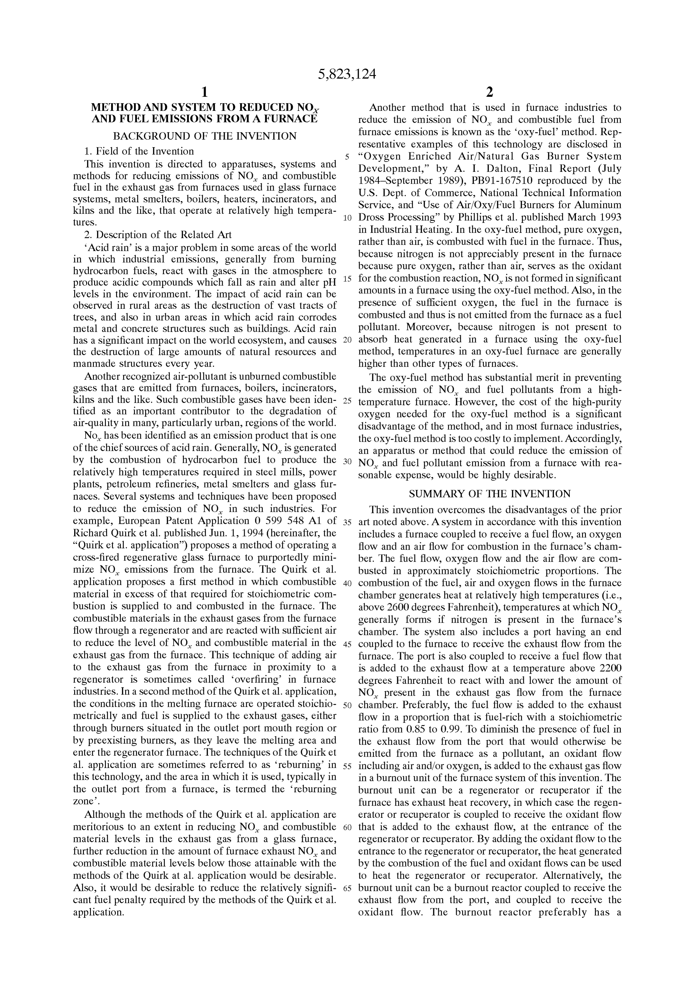
METHOD AND SYSTEM TO REDUCED NO Another method that is used in furnace industries to AND FUEL EMISSIONS FROM A FURNACE reduce the emission of NO, and combustible fuel from BACKGROUND OF THE INVENTION furnace emissions is known as the oxy-fuel method. Rep 1. Field of the Invention resentative examples of this technology are disclosed in “Oxygen Enriched Air/Natural Gas Burner System
This invention is directed to apparatuses, Systems and Development,” by A. I. Dalton, Final Report (July methods for reducing emissions of NO, and combustible 1984-September 1989), PB91-167510 reproduced by the fuel in the exhaust gas from furnaces used in glass furnace U.S. Dept. of Commerce, National Technical Information Systems, metal Smelters, boilers, heaters, incinerators, and Service, and “Use of Air/Oxy/Fuel Burners for Aluminum kilns and the like, that operate at relatively high tempera 1O Dross Processing” by Phillips et al. published March 1993 tureS.
2. Description of the Related Art in Industrial Heating. In the Oxy-fuel method, pure oxygen, rather than air, is combusted with fuel in the furnace. Thus,
Acid rain is a major problem in Some areas of the World because nitrogen is not appreciably in which industrial emissions, generally from burning because pure oxygen, rather than air,present Serves in the furnace as the oxidant hydrocarbon fuels, react with gases in the atmosphere to 15 produce acidic compounds which fall as rain and alter pH for the combustion reaction, NO is not formed in Significant levels in the environment. The impact of acid rain can be amounts in a furnace using the Oxy-fuel method. Also, in the observed in rural areas as the destruction of vast tracts of presence of Sufficient oxygen, the fuel in the furnace is trees, and also in urban areas in which acid rain corrodes combusted and thus is not emitted from the furnace as a fuel metal and concrete Structures Such as buildings. Acid rain pollutant. Moreover, because nitrogen is not present to has a significant impact on the World ecosystem, and causes absorb heat generated in a furnace using the Oxy-fuel the destruction of large amounts of natural resources and method, temperatures in an Oxy-fuel furnace are generally manmade Structures every year. higher than other types of furnaces. Another recognized air-pollutant is unburned combustible The Oxy-fuel method has Substantial merit in preventing gases that are emitted from furnaces, boilers, incinerators, the emission of NO, and fuel pollutants from a high kilns and the like. Such combustible gases have been iden 25 temperature furnace. However, the cost of the high-purity tified as an important contributor to the degradation of oxygen needed for the Oxy-fuel method is a significant air-quality in many, particularly urban, regions of the World. disadvantage of the method, and in most furnace industries, No has been identified as an emission product that is one the Oxy-fuel method is too costly to implement. Accordingly, of the chief Sources of acid rain. Generally, NO is generated an apparatus or method that could reduce the emission of by the combustion of hydrocarbon fuel to produce the NO, and fuel pollutant emission from a furnace with rea relatively high temperatures required in Steel mills, power Sonable expense, would be highly desirable. plants, petroleum refineries, metal Smelters and glass fur naces. Several Systems and techniques have been proposed SUMMARY OF THE INVENTION to reduce the emission of NO in such industries. For This invention overcomes the disadvantages of the prior example, European Patent Application 0 599 548 A1 of 35 art noted above. A System in accordance with this invention Richard Quirk et al. published Jun. 1, 1994 (hereinafter, the includes a furnace coupled to receive a fuel flow, an oxygen “Quirk et al. application”) proposes a method of operating a flow and an air flow for combustion in the furnace's cham cross-fired regenerative glass furnace to purportedly mini ber. The fuel flow, oxygen flow and the air flow are com mize NO emissions from the furnace. The Quirk et al. busted in approximately Stoichiometric proportions. The application proposes a first method in which combustible 40 combustion of the fuel, air and oxygen flows in the furnace material in excess of that required for Stoichiometric com chamber generates heat at relatively high temperatures (i.e., bustion is Supplied to and combusted in the furnace. The above 2600 degrees Fahrenheit), temperatures at which NO combustible materials in the exhaust gases from the furnace generally forms if nitrogen is present in the furnace's flow through a regenerator and are reacted with Sufficient air chamber. The System also includes a port having an end to reduce the level of NO, and combustible material in the 45 coupled to the furnace to receive the exhaust flow from the exhaust gas from the furnace. This technique of adding air furnace. The port is also coupled to receive a fuel flow that to the exhaust gas from the furnace in proximity to a is added to the exhaust flow at a temperature above 2200 regenerator is Sometimes called overfiring in furnace degrees Fahrenheit to react with and lower the amount of industries. In a Second method of the Quirk et al. application, NO present in the exhaust gas flow from the furnace the conditions in the melting furnace are operated Stoichio 50 chamber. Preferably, the fuel flow is added to the exhaust metrically and fuel is Supplied to the exhaust gases, either flow in a proportion that is fuel-rich with a Stoichiometric through burners situated in the outlet port mouth region or ratio from 0.85 to 0.99. To diminish the presence of fuel in by preexisting burners, as they leave the melting area and the exhaust flow from the port that would otherwise be enter the regenerator furnace. The techniques of the Quirk et emitted from the furnace as a pollutant, an oxidant flow al. application are Sometimes referred to as reburning in 55 including air and/or oxygen, is added to the exhaust gas flow this technology, and the area in which it is used, typically in in a burnout unit of the furnace system of this invention. The the outlet port from a furnace, is termed the reburning burnout unit can be a regenerator or recuperator if the Zone. furnace has exhaust heat recovery, in which case the regen Although the methods of the Quirk et al. application are erator or recuperator is coupled to receive the oxidant flow meritorious to an extent in reducing NO and combustible 60 that is added to the exhaust flow, at the entrance of the material levels in the exhaust gas from a glass furnace, regenerator or recuperator. By adding the oxidant flow to the further reduction in the amount of furnace exhaust NO, and entrance to the regenerator or recuperator, the heat generated combustible material levels below those attainable with the by the combustion of the fuel and oxidant flows can be used methods of the Quirk at al. application would be desirable. to heat the regenerator or recuperator. Alternatively, the Also, it would be desirable to reduce the relatively signifi 65 burnout unit can be a burnout reactor coupled to receive the cant fuel penalty required by the methods of the Quirk et al. exhaust flow from the port, and coupled to receive the application. oxidant flow. The burnout reactor preferably has a
Page 10
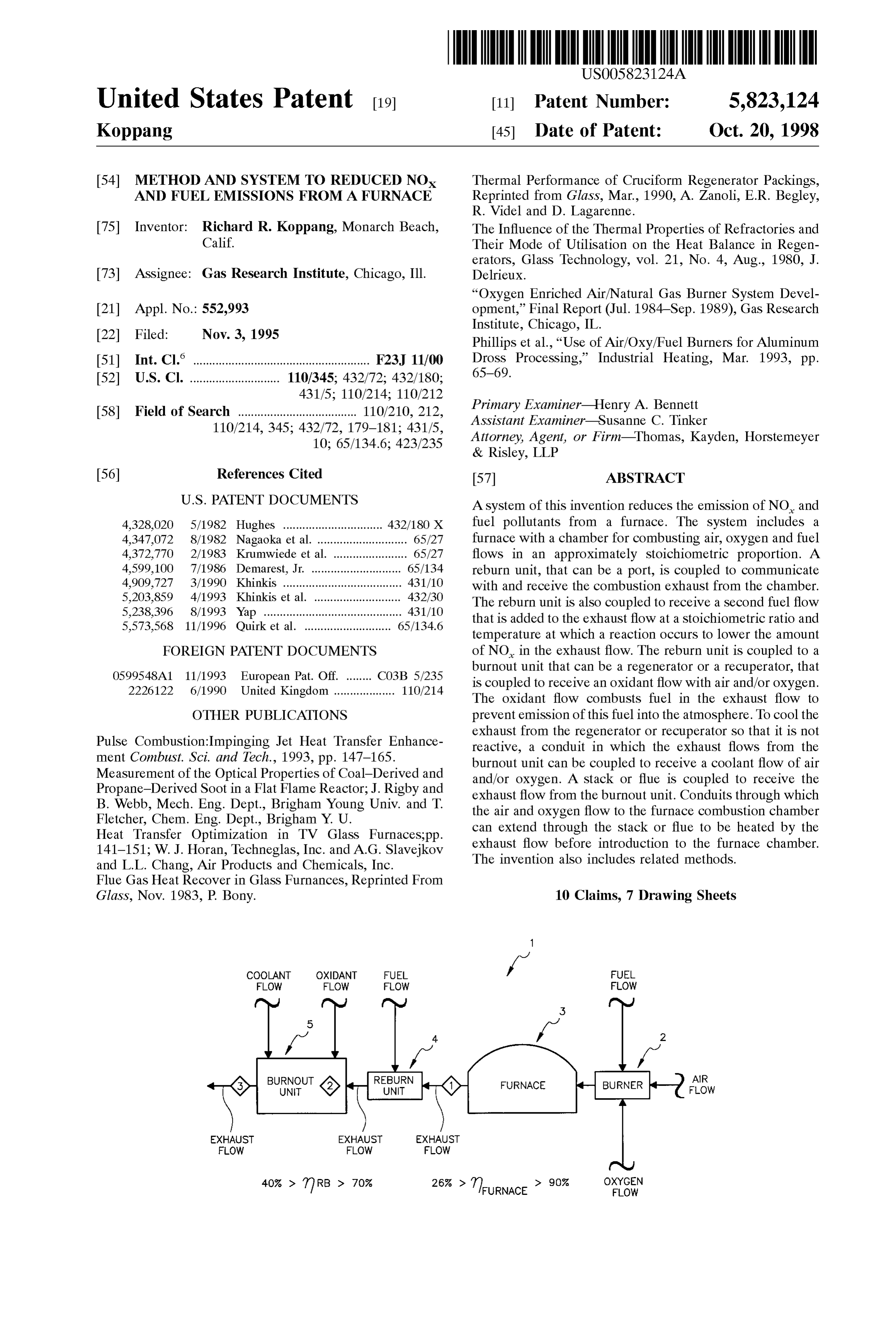
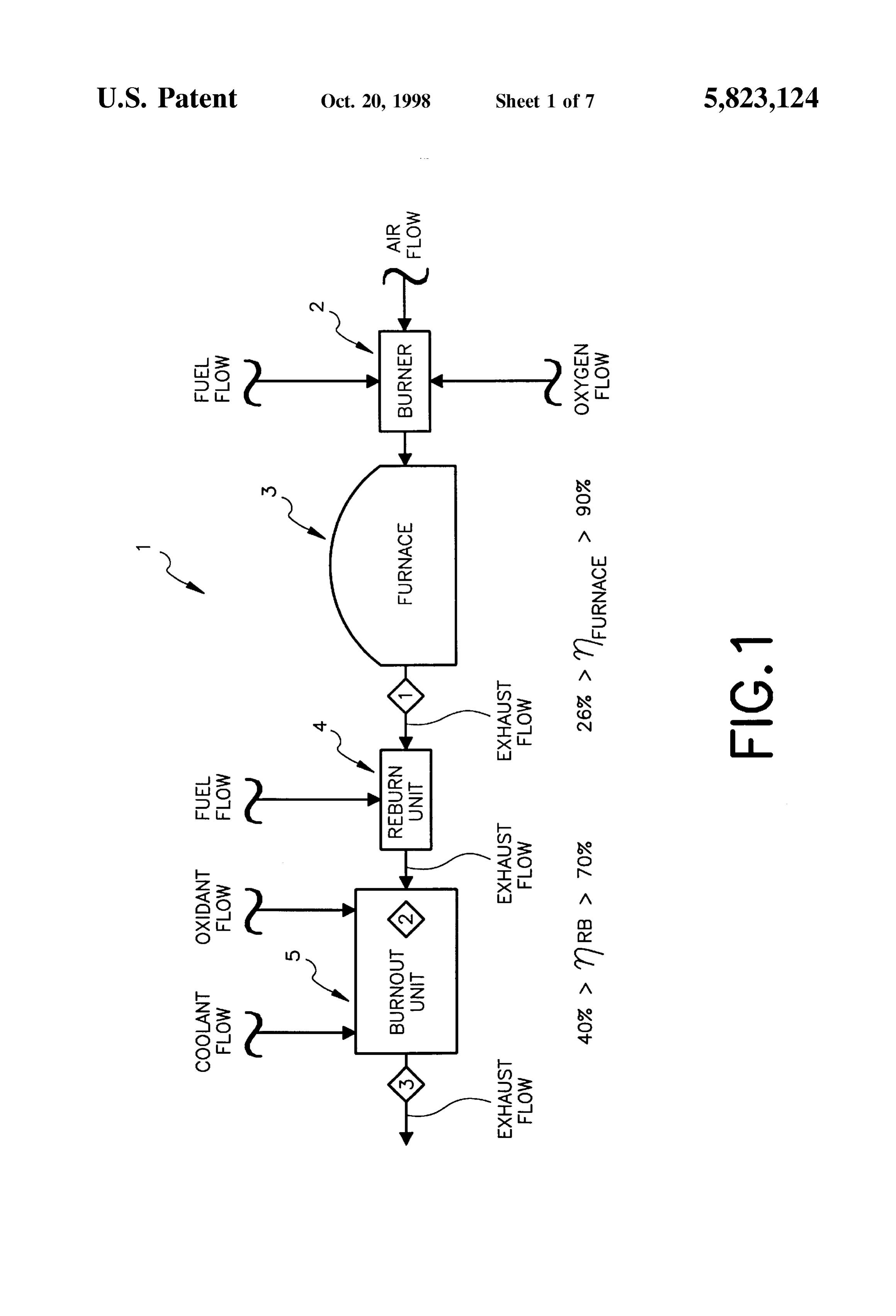
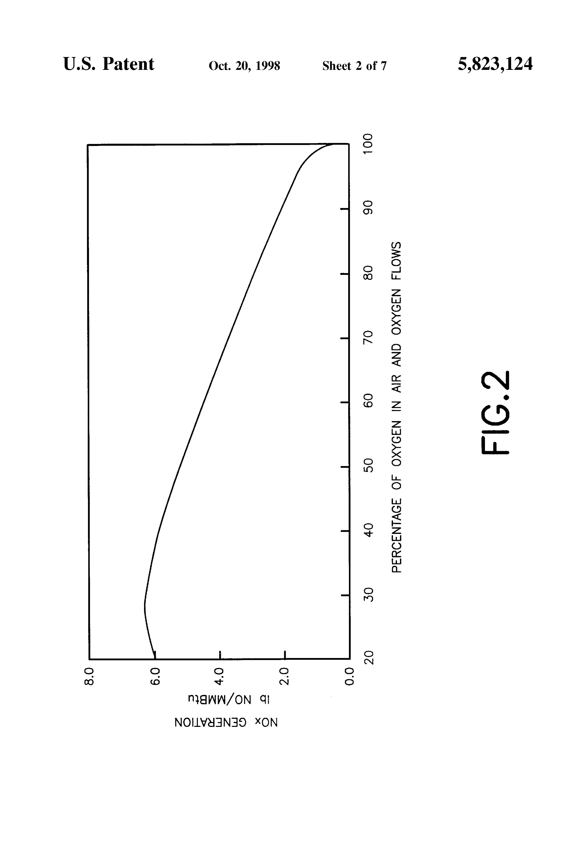
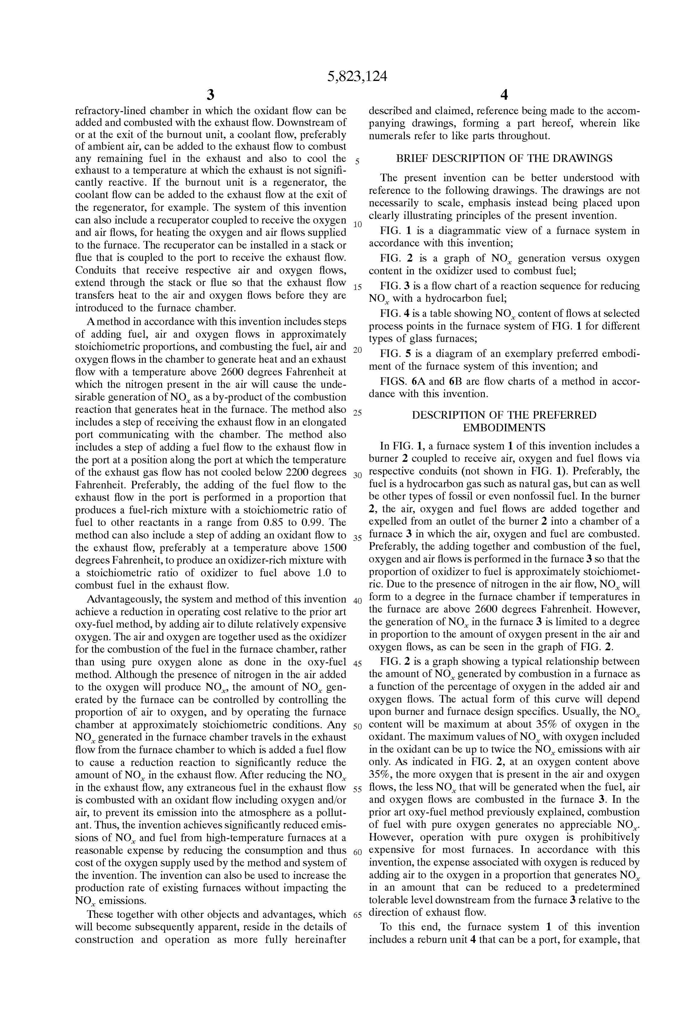
refractory-lined chamber in which the oxidant flow can be described and claimed, reference being made to the accom added and combusted with the exhaust flow. Downstream of panying drawings, forming a part hereof, wherein like or at the exit of the burnout unit, a coolant flow, preferably numerals refer to like parts throughout. of ambient air, can be added to the exhaust flow to combust any remaining fuel in the exhaust and also to cool the BRIEF DESCRIPTION OF THE DRAWINGS exhaust to a temperature at which the exhaust is not signifi cantly reactive. If the burnout unit is a regenerator, the The present invention can be better understood with coolant flow can be added to the exhaust flow at the exit of reference to the following drawings. The drawings are not the regenerator, for example. The System of this invention necessarily to Scale, emphasis instead being placed upon can also include a recuperator coupled to receive the oxygen clearly illustrating principles of the present invention. and air flows, for heating the oxygen and air flows Supplied FIG. 1 is a diagrammatic view of a furnace System in to the furnace. The recuperator can be installed in a Stack or accordance with this invention;
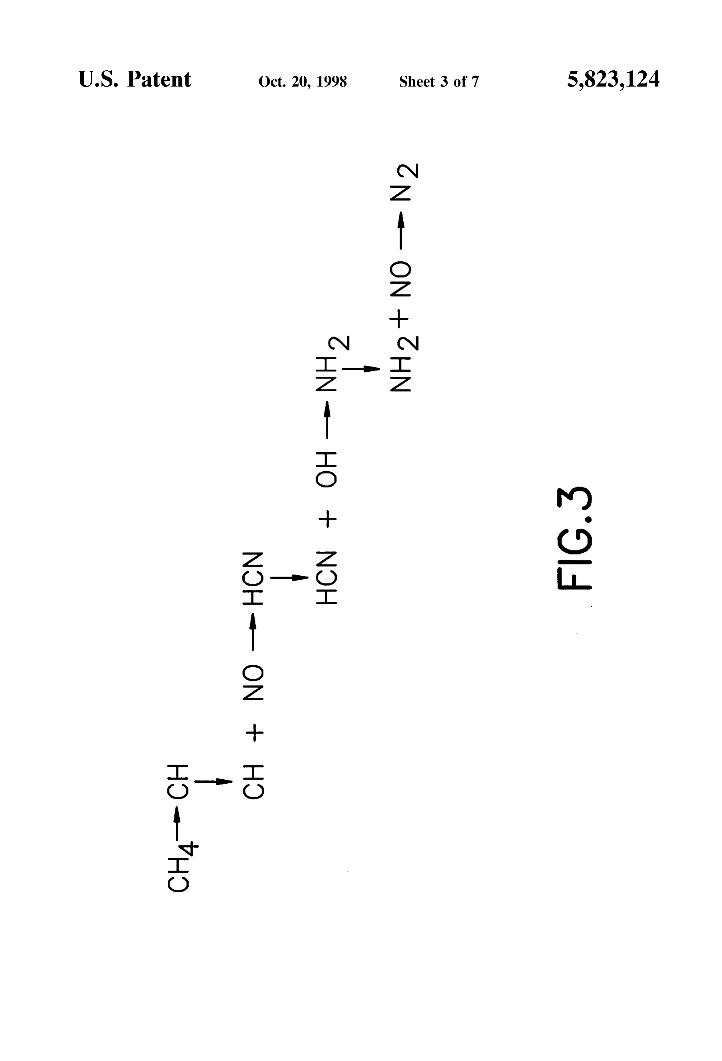
flue that is coupled to the port to receive the exhaust flow. FIG. 2 is a graph of NO generation versus oxygen Conduits that receive respective air and oxygen flows, content in the oxidizer used to combust fuel; extend through the stack or flue so that the exhaust flow 15 FIG. 3 is a flow chart of a reaction Sequence for reducing transferS heat to the air and oxygen flows before they are NO, with a hydrocarbon fuel;
introduced to the furnace chamber.
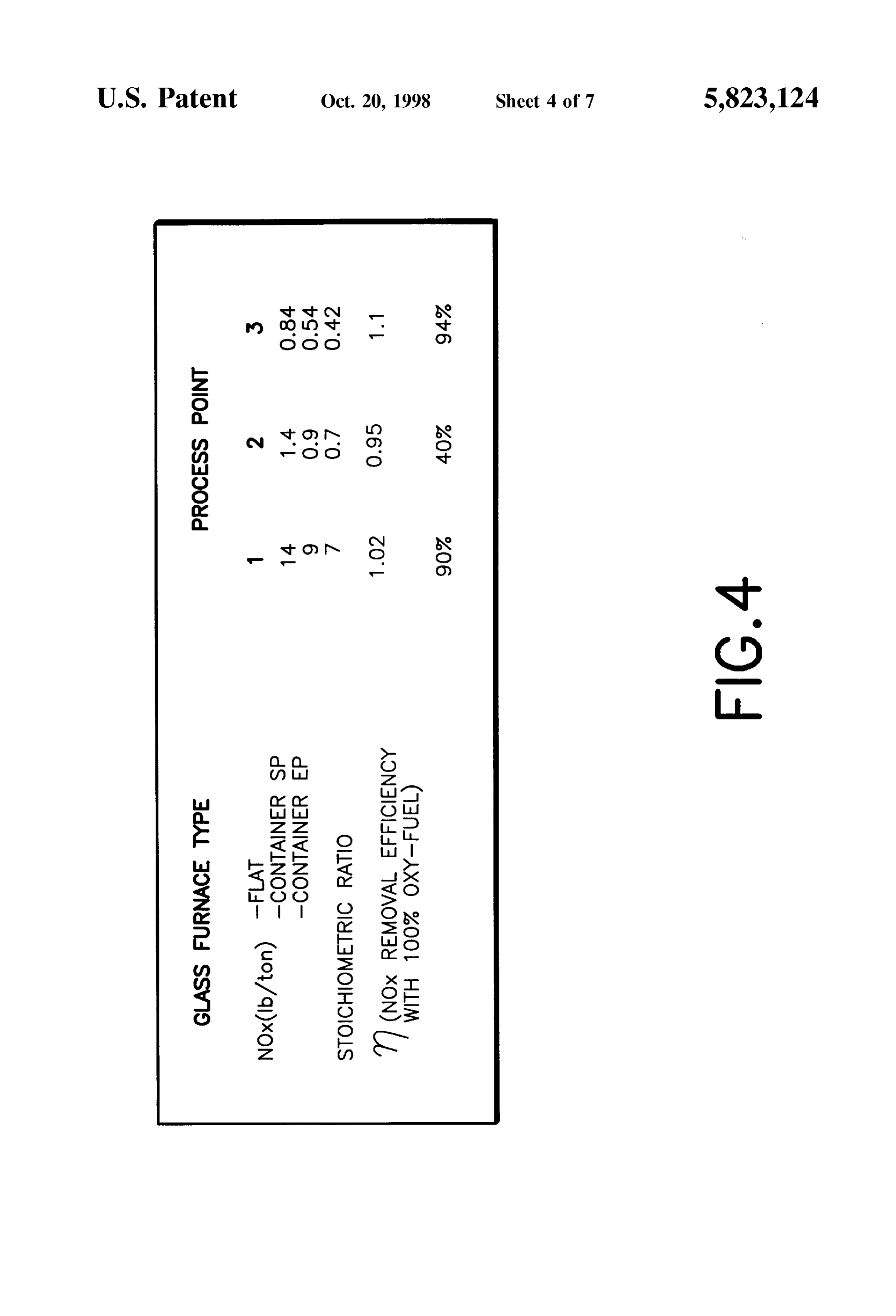
FIG. 4 is a table showing NO content of flows at selected
A method in accordance with this invention includes Steps process points in the furnace system of FIG. 1 for different of adding fuel, air and oxygen flows in approximately types of glass furnaces,
Stoichiometric proportions, and combusting the fuel, air and FIG. 5 is a diagram of an exemplary preferred embodi oxygen flows in the chamber to generate heat and an exhaust ment of the furnace System of this invention; and flow with a temperature above 2600 degrees Fahrenheit at which the nitrogen present in the air will cause the unde dance with6Athis
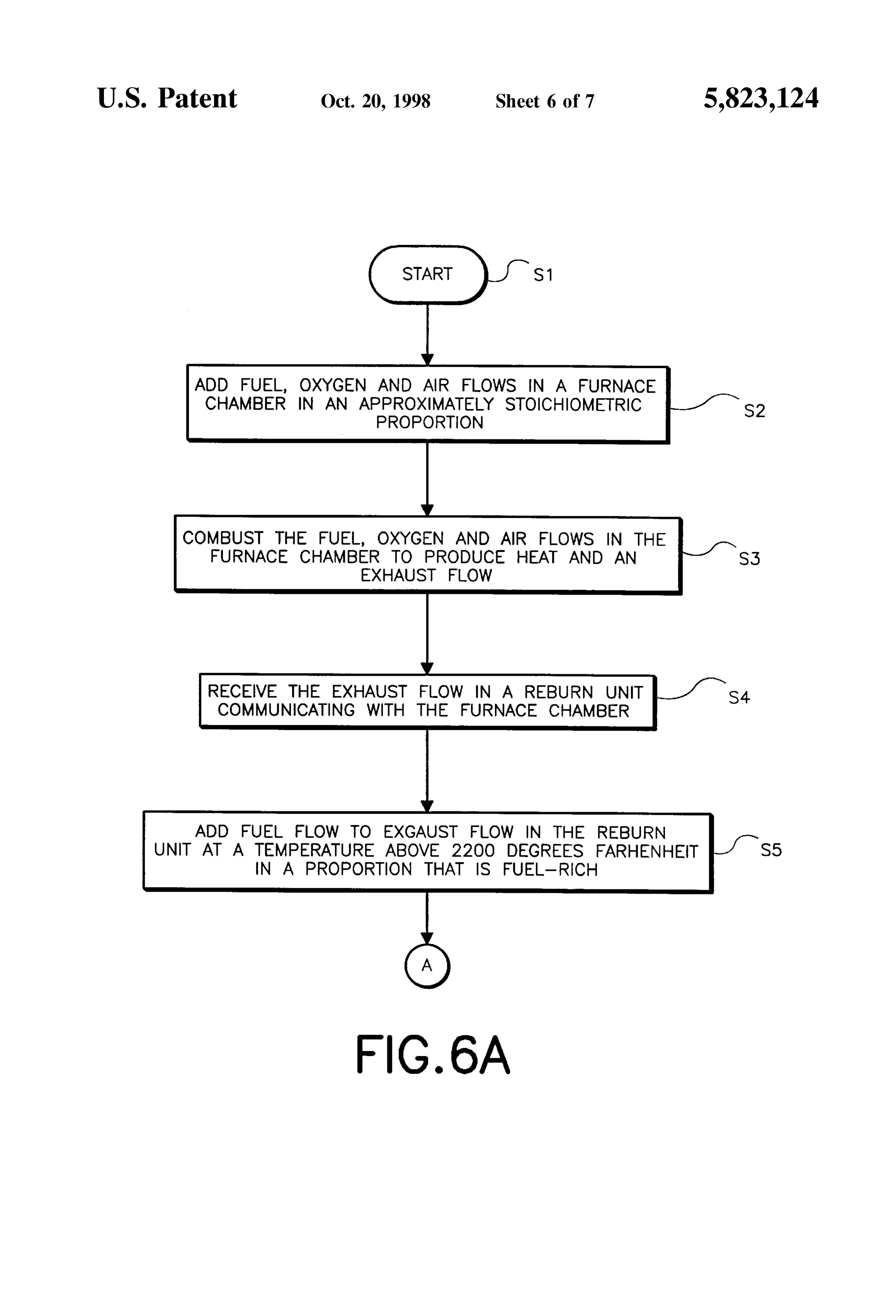
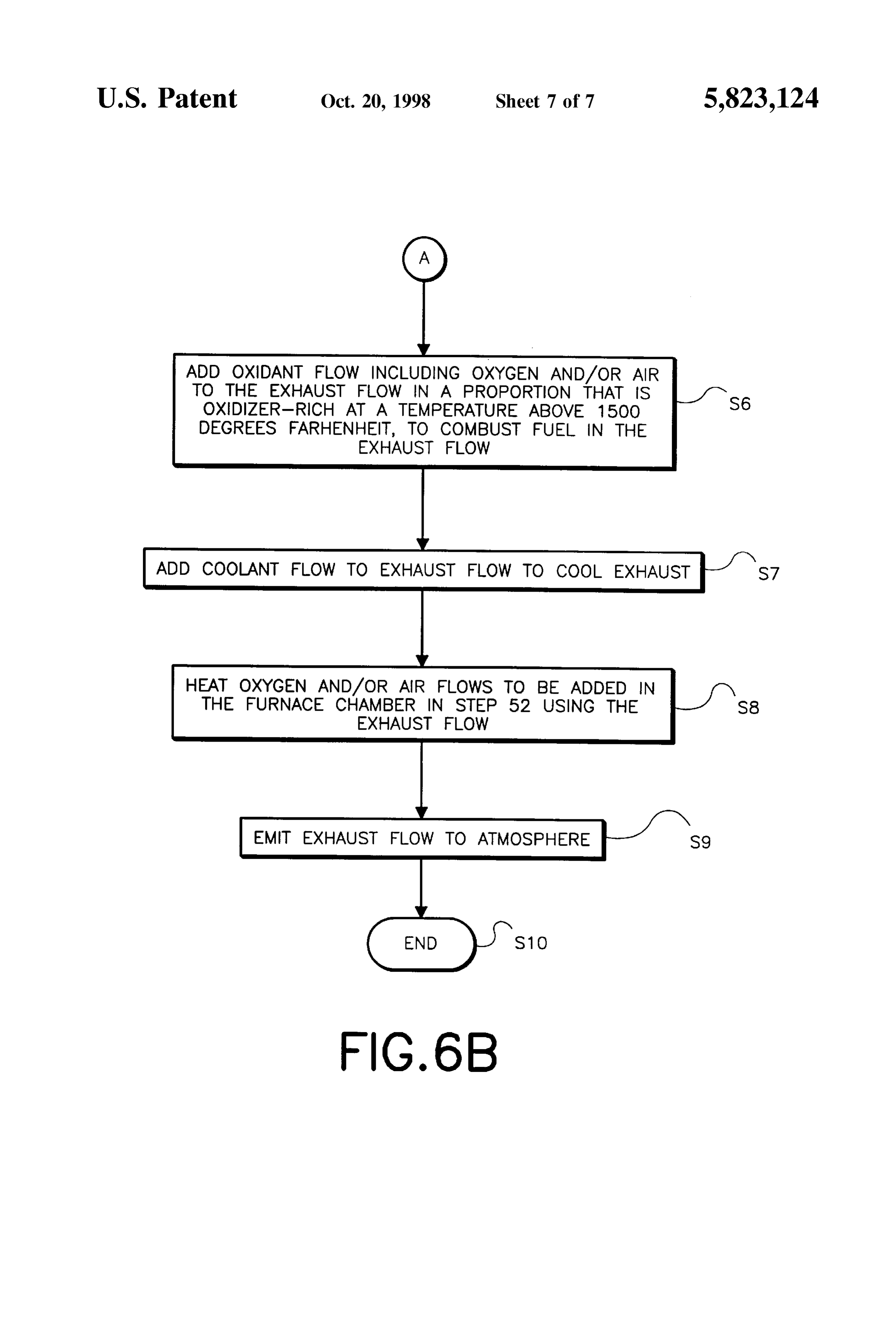
FIGS. and 6B are flow charts of a method in accor invention.
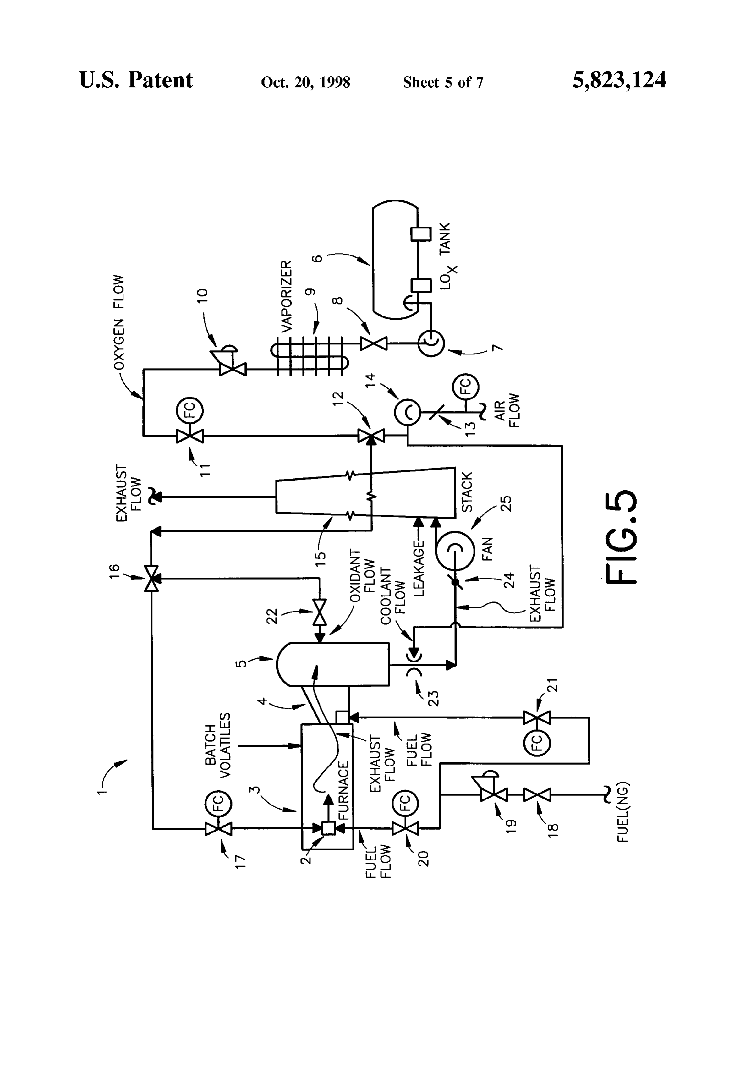
Sirable generation of NO as a by-product of the combustion reaction that generates heat in the furnace. The method also 25 DESCRIPTION OF THE PREFERRED includes a step of receiving the exhaust flow in an elongated EMBODIMENTS port communicating with the chamber. The method also includes a step of adding a fuel flow to the exhaust flow in In FIG. 1, a furnace system 1 of this invention includes a the port at a position along the port at which the temperature burner 2 coupled to receive air, oxygen and fuel flows Via of the exhaust gas flow has not cooled below 2200 degrees respective conduits (not shown in FIG. 1). Preferably, the Fahrenheit. Preferably, the adding of the fuel flow to the fuel is a hydrocarbon gas Such as natural gas, but can as well exhaust flow in the port is performed in a proportion that be other types of fossil or even nonfossil fuel. In the burner produces a fuel-rich mixture with a stoichiometric ratio of 2, the air, OXygen and fuel flows are added together and fuel to other reactants in a range from 0.85 to 0.99. The expelled from an outlet of the burner 2 into a chamber of a method can also include a step of adding an oxidant flow to 35 furnace 3 in which the air, oxygen and fuel are combusted. the exhaust flow, preferably at a temperature above 1500 Preferably, the adding together and combustion of the fuel, degrees Fahrenheit, to produce an oxidizer-rich mixture with oxygen and air flows is performed in the furnace 3 So that the a stoichiometric ratio of oxidizer to fuel above 1.0 to proportion of oxidizer to fuel is approximately Stoichiomet combust fuel in the exhaust flow. ric. Due to the presence of nitrogen in the air flow, NO will Advantageously, the System and method of this invention 40 form to a degree in the furnace chamber if temperatures in achieve a reduction in operating cost relative to the prior art the furnace are above 2600 degrees Fahrenheit. However, Oxy-fuel method, by adding air to dilute relatively expensive the generation of NO in the furnace 3 is limited to a degree oxygen. The air and oxygen are together used as the oxidizer in proportion to the amount of oxygen present in the air and for the combustion of the fuel in the furnace chamber, rather oxygen flows, as can be seen in the graph of FIG. 2. than using pure oxygen alone as done in the Oxy-fuel 45 FIG. 2 is a graph showing a typical relationship between method. Although the presence of nitrogen in the air added the amount of NO generated by combustion in a furnace as to the oxygen will produce NO, the amount of NO gen a function of the percentage of oxygen in the added air and erated by the furnace can be controlled by controlling the oxygen flows. The actual form of this curve will depend proportion of air to oxygen, and by operating the furnace upon burner and furnace design specifics. Usually, the NO chamber at approximately Stoichiometric conditions. Any 50 content will be maximum at about 35% of oxygen in the NO generated in the furnace chamber travels in the exhaust oxidant. The maximum values of NO with oxygen included flow from the furnace chamber to which is added a fuel flow in the oxidant can be up to twice the NO emissions with air to cause a reduction reaction to Significantly reduce the only. AS indicated in FIG. 2, at an oxygen content above amount of NO in the exhaust flow. After reducing the NO 35%, the more oxygen that is present in the air and oxygen in the exhaust flow, any extraneous fuel in the exhaust flow 55 flows, the less NO that will be generated when the fuel, air is combusted with an oxidant flow including oxygen and/or and oxygen flows are combusted in the furnace 3. In the air, to prevent its emission into the atmosphere as a pollut prior art oxy-fuel method previously explained, combustion ant. Thus, the invention achieves Significantly reduced emis of fuel with pure oxygen generates no appreciable NO. Sions of NO and fuel from high-temperature furnaces at a However, operation with pure oxygen is prohibitively reasonable expense by reducing the consumption and thus 60 expensive for most furnaces. In accordance with this cost of the oxygen Supply used by the method and System of invention, the expense associated with oxygen is reduced by the invention. The invention can also be used to increase the adding air to the oxygen in a proportion that generates NO production rate of existing furnaces without impacting the in an amount that can be reduced to a predetermined NO emissions. tolerable level downstream from the furnace 3 relative to the These together with other objects and advantages, which 65 direction of exhaust flow.
will become Subsequently apparent, reside in the details of To this end, the furnace system 1 of this invention construction and operation as more fully hereinafter includes a reburn unit 4 that can be a port, for example, that
Page 11
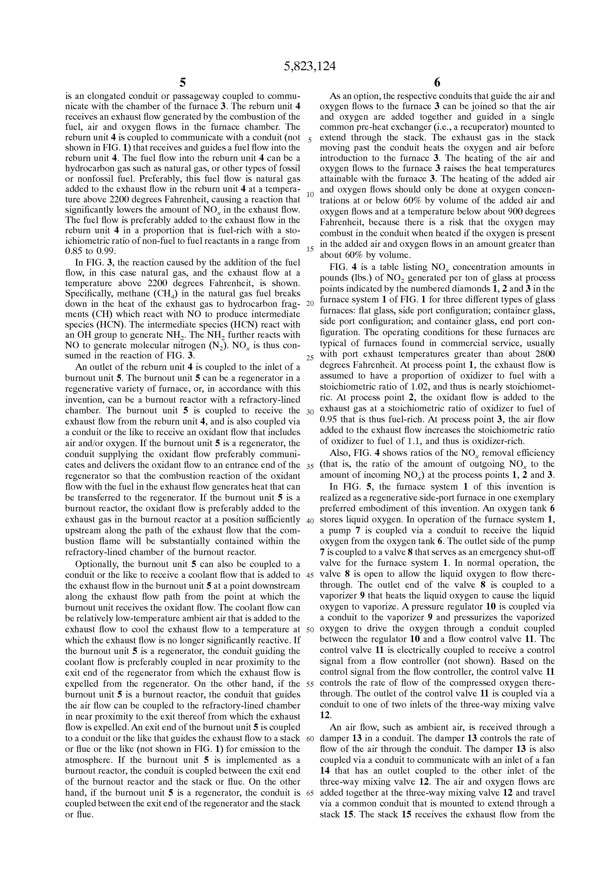
S 6 is an elongated conduit or passageway coupled to commu AS an option, the respective conduits that guide the air and nicate with the chamber of the furnace 3. The reburn unit 4 oxygen flows to the furnace 3 can be joined So that the air receives an exhaust flow generated by the combustion of the and oxygen are added together and guided in a single fuel, air and oxygen flows in the furnace chamber. The common pre-heat exchanger (i.e., a recuperator) mounted to reburn unit 4 is coupled to communicate with a conduit (not extend through the Stack. The exhaust gas in the Stack shown in FIG. 1) that receives and guides a fuel flow into the moving past the conduit heats the oxygen and air before reburn unit 4. The fuel flow into the reburn unit 4 can be a introduction to the furnace 3. The heating of the air and hydrocarbon gas Such as natural gas, or other types of fossil oxygen flows to the furnace 3 raises the heat temperatures or nonfossil fuel. Preferably, this fuel flow is natural gas attainable with the furnace 3. The heating of the added air added to the exhaust flow in the reburn unit 4 at a tempera and oxygen flows should only be done at oxygen concen ture above 2200 degrees Fahrenheit, causing a reaction that trations at or below 60% by volume of the added air and significantly lowers the amount of NO in the exhaust flow. oxygen flows and at a temperature below about 900 degrees The fuel flow is preferably added to the exhaust flow in the Fahrenheit, because there is a risk that the oxygen may reburn unit 4 in a proportion that is fuel-rich with a sto combust in the conduit when heated if the oxygen is present ichiometric ratio of non-fuel to fuel reactants in a range from 15 in the added air and oxygen flows in an amount greater than
about 60% by volume.
In FIG. 3, the reaction caused by the addition of the fuel FIG. 4 is a table listing NO concentration amounts in flow, in this case natural gas, and the exhaust flow at a pounds (lbs.) of NO generated per ton of glass at process temperature above 2200 degrees Fahrenheit, is shown. points indicated
Specifically, methane (CH) in the natural gas fuel breaks furnace system 1byofthe numbered diamonds 1, 2 and 3 in the FIG. 1 for three different types of glass down in the heat of the exhaust gas to hydrocarbon frag furnaces: flat glass, Side port configuration; container glass, ments (CH) which react with NO to produce intermediate species (HCN). The intermediate species (HCN) react with Side port configuration; and container glass, end port con an OH group to generate NH. The NH further reacts with figuration. The operating conditions for these furnaces are NO to generate molecular nitrogen (N). NO is thus con typical of furnaces found in commercial Service, usually Sumed in the reaction of FIG. 3. 25 with port exhaust temperatures greater than about 2800 An outlet of the reburn unit 4 is coupled to the inlet of a degrees Fahrenheit. At proceSS point 1, the exhaust flow is burnout unit 5. The burnout unit 5 can be a regenerator in a assumed to have a proportion of oxidizer to fuel with a regenerative variety of furnace, or, in accordance with this Stoichiometric ratio of 1.02, and thus is nearly Stoichiomet invention, can be a burnout reactor with a refractory-lined ric. At process point 2, the oxidant flow is added to the chamber. The burnout unit 5 is coupled to receive the exhaust gas at a Stoichiometric ratio of oxidizer to fuel of exhaust flow from the reburn unit 4, and is also coupled via 0.95 that is thus fuel-rich. At process point 3, the air flow a conduit or the like to receive an oxidant flow that includes added to the exhaust flow increases the Stoichiometric ratio air and/or oxygen. If the burnout unit 5 is a regenerator, the of oxidizer to fuel of 1.1, and thus is oxidizer-rich. conduit Supplying the oxidant flow preferably communi Also, FIG. 4 shows ratios of the NO removal efficiency cates and delivers the oxidant flow to an entrance end of the 35 (that is, the ratio of the amount of outgoing NO to the regenerator So that the combustion reaction of the oxidant amount of incoming NO) at the process points 1, 2 and 3. flow with the fuel in the exhaust flow generates heat that can In FIG. 5, the furnace system 1 of this invention is be transferred to the regenerator. If the burnout unit 5 is a realized as a regenerative side-port furnace in one exemplary burnout reactor, the oxidant flow is preferably added to the preferred embodiment of this invention. An oxygen tank 6 exhaust gas in the burnout reactor at a position Sufficiently 40 Stores liquid oxygen. In operation of the furnace System 1, upstream along the path of the exhaust flow that the com a pump 7 is coupled via a conduit to receive the liquid bustion flame will be substantially contained within the oxygen from the oxygen tank 6. The outlet Side of the pump refractory-lined chamber of the burnout reactor. 7 is coupled to a valve 8 that Serves as an emergency shut-off Optionally, the burnout unit 5 can also be coupled to a Valve for the furnace System 1. In normal operation, the conduit or the like to receive a coolant flow that is added to 45 valve 8 is open to allow the liquid oxygen to flow there the exhaust flow in the burnout unit 5 at a point downstream through. The outlet end of the valve 8 is coupled to a along the exhaust flow path from the point at which the Vaporizer 9 that heats the liquid oxygen to cause the liquid burnout unit receives the oxidant flow. The coolant flow can oxygen to vaporize. A pressure regulator 10 is coupled via be relatively low-temperature ambient air that is added to the a conduit to the vaporizer 9 and pressurizes the vaporized exhaust flow to cool the exhaust flow to a temperature at 50 oxygen to drive the oxygen through a conduit coupled which the exhaust flow is no longer Significantly reactive. If between the regulator 10 and a flow control valve 11. The the burnout unit 5 is a regenerator, the conduit guiding the control valve 11 is electrically coupled to receive a control coolant flow is preferably coupled in near proximity to the signal from a flow controller (not shown). Based on the exit end of the regenerator from which the exhaust flow is control signal from the flow controller, the control valve 11 expelled from the regenerator. On the other hand, if the 55 controls the rate of flow of the compressed oxygen there burnout unit 5 is a burnout reactor, the conduit that guides through. The outlet of the control valve 11 is coupled via a the air flow can be coupled to the refractory-lined chamber conduit to one of two inlets of the three-way mixing valve in near proximity to the exit thereof from which the exhaust 12.
flow is expelled. An exit end of the burnout unit 5 is coupled An air flow, Such as ambient air, is received through a to a conduit or the like that guides the exhaust flow to a Stack 60 damper 13 in a conduit. The damper 13 controls the rate of or flue or the like (not shown in FIG. 1) for emission to the flow of the air through the conduit. The damper 13 is also atmosphere. If the burnout unit 5 is implemented as a coupled via a conduit to communicate with an inlet of a fan burnout reactor, the conduit is coupled between the exit end 14 that has an outlet coupled to the other inlet of the of the burnout reactor and the stack or flue. On the other three-way mixing valve 12. The air and oxygen flows are hand, if the burnout unit 5 is a regenerator, the conduit is 65 added together at the three-way mixing valve 12 and travel coupled between the exit end of the regenerator and the Stack via a common conduit that is mounted to extend through a or flue. stack 15. The stack 15 receives the exhaust flow from the
Page 12
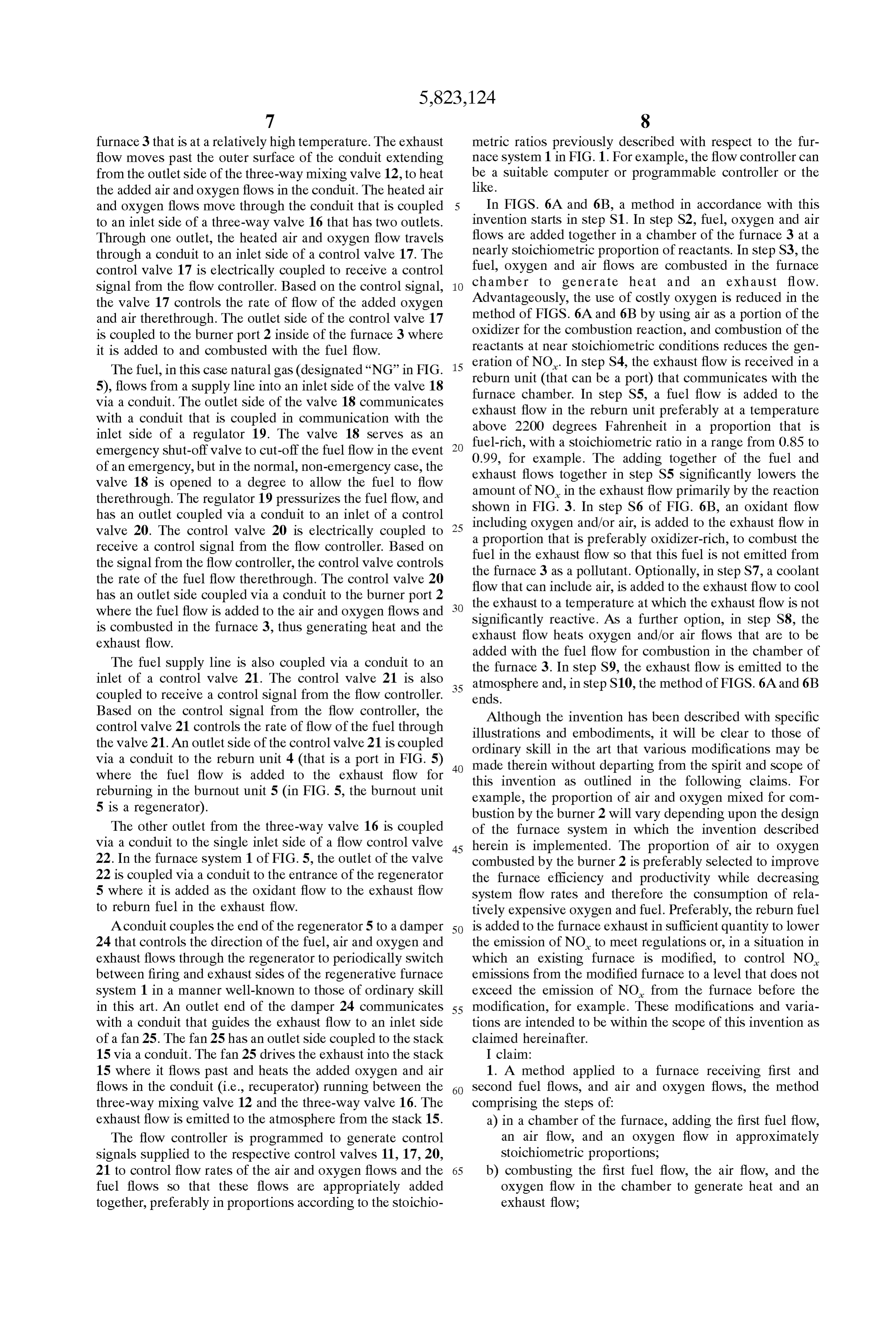
furnace 3 that is at a relatively high temperature. The exhaust metric ratioS previously described with respect to the fur flow moves past the Outer Surface of the conduit extending nace system 1 in FIG.1. For example, the flow controller can from the outlet side of the three-way mixing valve 12, to heat be a Suitable computer or programmable controller or the the added air and oxygen flows in the conduit. The heated air like.
and oxygen flows move through the conduit that is coupled In FIGS. 6A and 6B, a method in accordance with this to an inlet side of a three-way valve 16 that has two outlets. invention Starts in Step S1. In Step S2, fuel, oxygen and air Through one outlet, the heated air and oxygen flow travels flows are added together in a chamber of the furnace 3 at a through a conduit to an inlet side of a control valve 17. The nearly Stoichiometric proportion of reactants. In Step S3, the control valve 17 is electrically coupled to receive a control fuel, oxygen and air flows are combusted in the furnace Signal from the flow controller. Based on the control Signal, chamber to generate heat and an exhaust flow. the valve 17 controls the rate of flow of the added oxygen Advantageously, the use of costly oxygen is reduced in the and air therethrough. The outlet side of the control valve 17 method of FIGS. 6A and 6B by using air as a portion of the is coupled to the burner port 2 inside of the furnace 3 where oxidizer for the combustion reaction, and combustion of the it is added to and combusted with the fuel flow. reactants at near Stoichiometric conditions reduces the gen The fuel, in this case natural gas (designated “NG” in FIG. 15 eration of NO. In step S4, the exhaust flow is received in a 5), flows from a supply line into an inlet side of the valve 18 reburn unit (that can be a port) that communicates with the via a conduit. The outlet side of the valve 18 communicates furnace chamber. In step S5, a fuel flow is added to the with a conduit that is coupled in communication with the exhaust flow in the reburn unit preferably at a temperature inlet side of a regulator 19. The valve 18 serves as an fuel-rich, withdegrees above 2200 Fahrenheit in a proportion that is emergency shut-off valve to cut-off the fuel flow in the event 0.99, for example. The addingratio a stoichiometric in a range from 0.85 to together of the fuel and of an emergency, but in the normal, non-emergency case, the valve 18 is opened to a degree to allow the fuel to flow exhaust flows together in step S5 significantly lowers the amount of NO in the exhaust flow primarily by the reaction therethrough. The regulator 19 pressurizes the fuel flow, and shown in FIG. 3. In step S6 of FIG. 6B, an oxidant flow has an outlet coupled via a conduit to an inlet of a control including oxygen and/or air, is added to the exhaust flow in
valve 20. The control valve 20 is electrically coupled to a proportion receive a control Signal from the flow controller. Based on fuel in the exhaust that is preferably oxidizer-rich, to combust the flow so that this fuel is not emitted from the signal from the flow controller, the control valve controls the furnace 3 as a pollutant. Optionally, in Step S7, a coolant the rate of the fuel flow therethrough. The control valve 20 flow that can include air, is added to the exhaust flow to cool has an outlet Side coupled via a conduit to the burner port 2 where the fuel flow is added to the air and oxygen flows and the exhaust to a temperature at which the exhaust flow is not is combusted in the furnace 3, thus generating heat and the exhaust flow reactive.
Significantly As a further option, in Step S8, the heats oxygen and/or air flows that are to be exhaust flow.
added with the fuel flow for combustion in the chamber of
The fuel Supply line is also coupled via a conduit to an the furnace 3. In step S9, the exhaust flow is emitted to the inlet of a control valve 21. The control valve 21 is also atmosphere and, in step S10, the method of FIGS. 6A and 6B coupled to receive a control Signal from the flow controller. 35 ends.
Based on the control signal from the flow controller, the Although the invention has been described with specific control valve 21 controls the rate of flow of the fuel through illustrations and embodiments, it will be clear to those of the valve 21. An outlet side of the control valve 21 is coupled ordinary skill in the art that various modifications may be via a conduit to the reburn unit 4 (that is a port in FIG. 5) 40 made therein without departing from the Spirit and Scope of where the fuel flow is added to the exhaust flow for reburning in the burnout unit 5 (in FIG. 5, the burnout unit this invention as outlined in the following claims. For example, the proportion of air and oxygen mixed for com 5 is a regenerator). bustion by the burner 2 will vary depending upon the design The other outlet from the three-way valve 16 is coupled of the furnace system in which the invention described via a conduit to the Single inlet Side of a flow control valve 45 herein is implemented. The proportion of air to oxygen 22. In the furnace system 1 of FIG. 5, the outlet of the valve combusted by the burner 2 is preferably selected to improve 22 is coupled via a conduit to the entrance of the regenerator the furnace efficiency and productivity while decreasing 5 where it is added as the oxidant flow to the exhaust flow System flow rates and therefore the consumption of rela to reburn fuel in the exhaust flow. tively expensive oxygen and fuel. Preferably, the reburn fuel A conduit couples the end of the regenerator 5 to a damper 50 is added to the furnace exhaust in Sufficient quantity to lower 24 that controls the direction of the fuel, air and oxygen and the emission of NO to meet regulations or, in a situation in exhaust flows through the regenerator to periodically Switch which an existing furnace is modified, to control NO between firing and exhaust Sides of the regenerative furnace emissions from the modified furnace to a level that does not System 1 in a manner well-known to those of ordinary skill exceed the emission of NO from the furnace before the in this art. An outlet end of the damper 24 communicates 55 modification, for example. These modifications and varia with a conduit that guides the exhaust flow to an inlet Side tions are intended to be within the Scope of this invention as of a fan 25. The fan 25 has an outlet side coupled to the stack claimed hereinafter.
15 via a conduit. The fan 25 drives the exhaust into the stack I claim:
15 where it flows past and heats the added oxygen and air 1. A method applied to a furnace receiving first and flows in the conduit (i.e., recuperator) running between the 60 Second fuel flows, and air and oxygen flows, the method three-way mixing valve 12 and the three-way valve 16. The comprising the Steps of:
exhaust flow is emitted to the atmosphere from the stack 15. a) in a chamber of the furnace, adding the first fuel flow, The flow controller is programmed to generate control an air flow, and an oxygen flow in approximately signals supplied to the respective control valves 11, 17, 20, Stoichiometric proportions, 21 to control flow rates of the air and oxygen flows and the 65 b) combusting the first fuel flow, the air flow, and the fuel flows So that these flows are appropriately added Oxygen flow in the chamber to generate heat and an together, preferably in proportions according to the Stoichio exhaust flow;
Page 13
c) receiving the exhaust flow in a reburn unit in fluid g) heating at least one of the air and oxygen flows communication with the chamber, the exhaust flow Supplied to the furnace chamber for use in performing cooling as the exhaust flow travels through the reburn Said step (a).
unit, 5. The method of claim 1, wherein the oxidant flow is d) adding the second fuel flow to the exhaust flow in the added to the exhaust flow in a burnout unit that is in fluid reburn unit at a position along the reburn unit at which communication with the reburn unit, the exhaust flow trav the temperature of the exhaust gas flow has not cooled eling through the burnout unit from an entrance end to an below 2200 degrees Fahrenheit, the adding of the exit end of the burnout unit.
Second fuel flow to the exhaust flow producing a 6. The method of claim 5, wherein the burnout unit is a fuel-rich mixture; and regenerator and the oxidant flow is added to the exhaust flow (e) downstream relative to the direction of the exhaust adjacent the entrance end of the regenerator. adding an oxidant flow to the exhaust flow in a burnout 7. The method of claim 5, wherein the burnout unit is a unit in fluid communication with the return unit to produce an oxidizer-rich mixture with a Stoichiometric recuperator and the oxidant flow is added to the exhaust flow ratio above 1.0 to combust fuel in the exhaust flow, 15 adjacent the entrance end of the recuperator. wherein the oxidant comprises a mixture of air and the8.furnace
The method of claim 1, wherein the exhaust flow leaves at a temperature above 2600 degrees Fahrenheit.
OXygen gaS.
2. A method as claimed in claim 1, further comprising the 9. The method of claim 8, wherein the fuel-rich mixture Step of, downstream relative to the direction of the exhaust resulting from the addition of the second fuel flow to the flow from a position along the path of the exhaust flow exhaust flow has a Stoichiometric ratio of non-fuel reactants where said step (e) is performed, adding a coolant flow to the to fuel in a range from 0.85 to 0.99. exhaust flow to cool the exhaust flow. 10. The method of claim 9, wherein the oxidant flow is 3. A method as claimed in claim 2, wherein the coolant added to the exhaust flow at a temperature above 1500 flow includes air.
degrees Fahrenheit.
4. A method as claimed in claim 1, further comprising the
Step of
Provenance
- Collection
- Cited prior art
- Original PDF
- patentimages.storage.googleapis.com →
- Filed
- 1995-11-03
- Pages
- 13
- Method
- pdftotext (the PDF's own text layer) + pdftoppm 300dpi page scans
- Source
- Google Patents bibliographic record
- Granted
- 1998-10-20
- Inventors
- Richard R. Koppang; GTI Energy
- Transcribed from
- patentimages.storage.googleapis.com →