patent · US6136279
Reformer furnace with internal recirculation
24 October 2000
Page 1 — bibliographic record
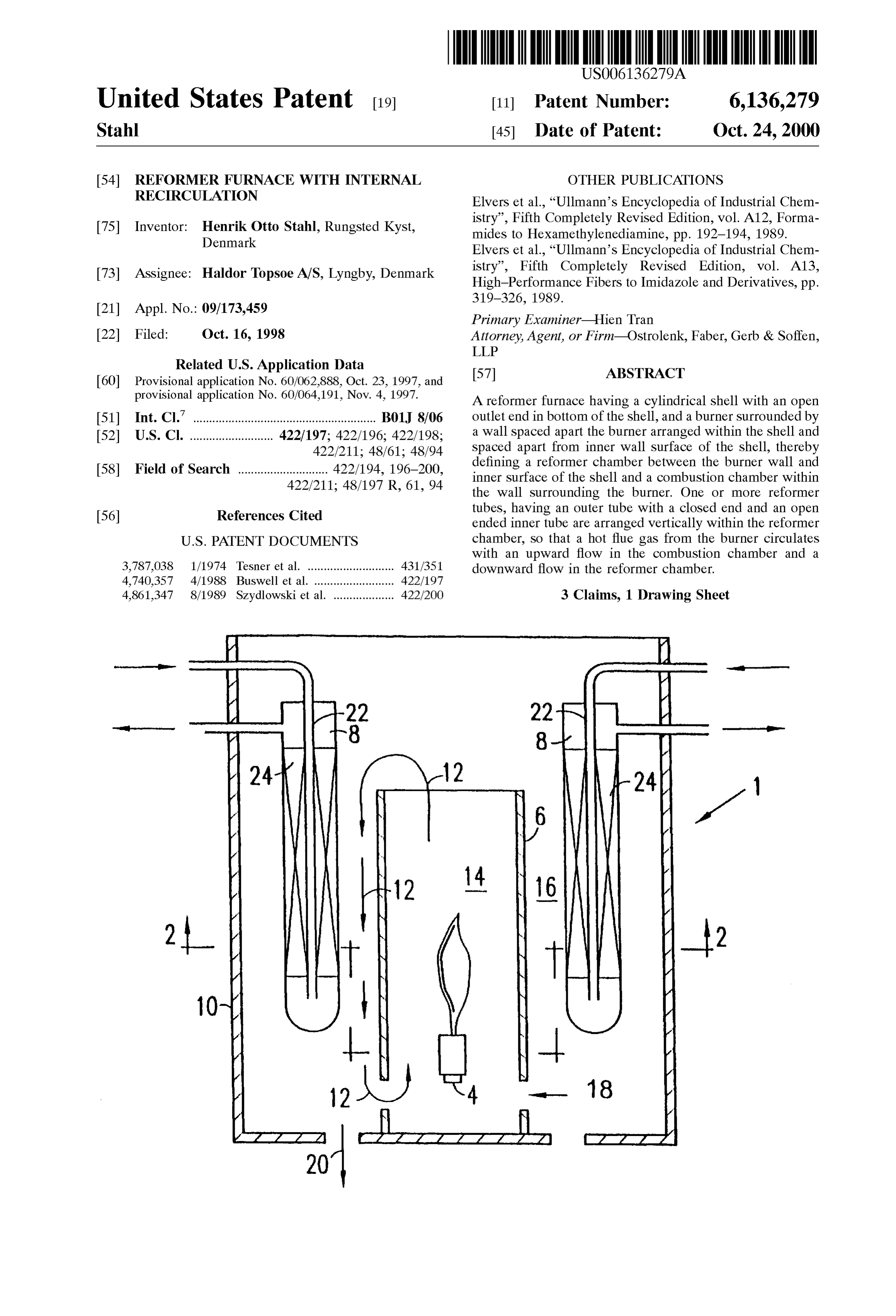
United States Patent (19) 11 Patent Number: 6,136,279 Stahl (45) Date of Patent: Oct. 24, 2000 54 REFORMER FURNACE WITH INTERNAL OTHER PUBLICATIONS RECIRCULATION Elvers et al., “Ullmann's Encyclopedia of Industrial Chem 75 Inventor: Henrik Otto Stahl, Rungsted Kyst, istry”, Fifth Completely Revised Edition, vol. A12, Forma Denmark mides to Hexamethylenediamine, pp. 192-194, 1989. Elvers et al., “Ullmann's Encyclopedia of Industrial Chem 73 Assignee: Haldor Topsoe A/S, Lyngby, Denmark istry”, Fifth Completely Revised Edition, vol. A13, High-Performance Fibers to Imidazole and Derivatives, pp.
Primary Examiner Hien Tran 22 Filed: Oct. 16, 1998 Attorney, Agent, or Firm-Ostrolenk, Faber, Gerb & Soffen, LLP
Related U.S. Application Data 57 ABSTRACT 60 Provisional application No. 60/062.888, Oct. 23, 1997, and provisional application No. 60/064,191, Nov. 4, 1997. A reformer furnace having a cylindrical shell with an open (51) Int. Cl. ................................................... B01J 8/06 outlet end in bottom of the shell, and a burner Surrounded by 52 U.S. Cl. .......................... 422/197; 422/196; 422/198; a wall spaced apart the burner arranged within the shell and 422/211; 48/61; 48/94 Spaced apart from inner wall Surface of the shell, thereby 58) Field of Search 422/194, 196-200 defining a reformer chamber between the burner wall and inner Surface of the shell and a combustion chamber within 422/211; 48/197 R, 61,94 the wall surrounding the burner. One or more reformer tubes, having an Outer tube with a closed end and an open 56) References Cited ended inner tube are arranged vertically within the reformer
with an upward flow in the combustion chamber and a 3,787,038 1/1974 Tesner et al. ........................... 431/351 downward flow in the reformer chamber. 4,740,357 4/1988 Buswell et al....... ... 422/197 4,861,347 8/1989 Szydlowski et al. ................... 422/200 3 Claims, 1 Drawing Sheet
Page 2
Drawing sheet — no readable text.
Page 3
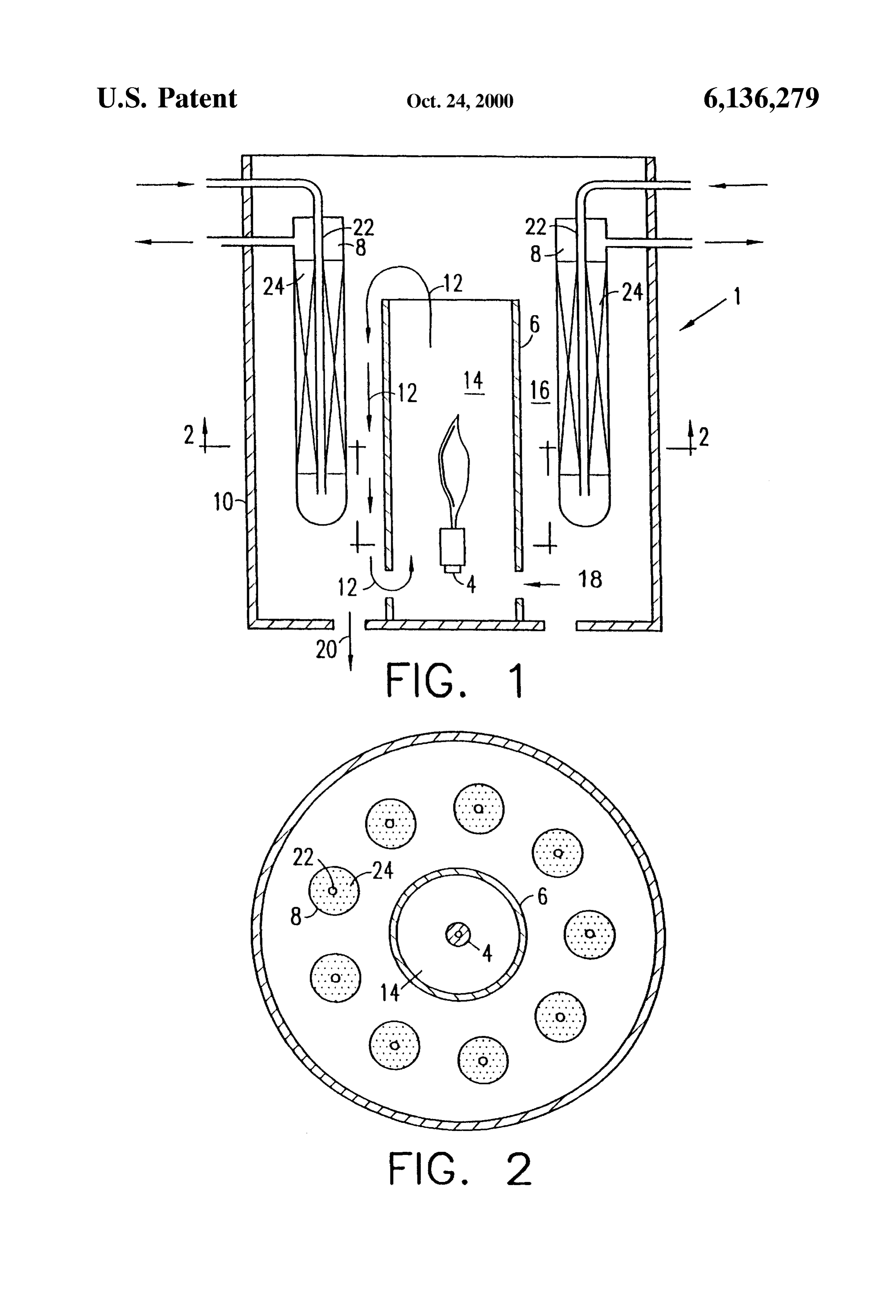
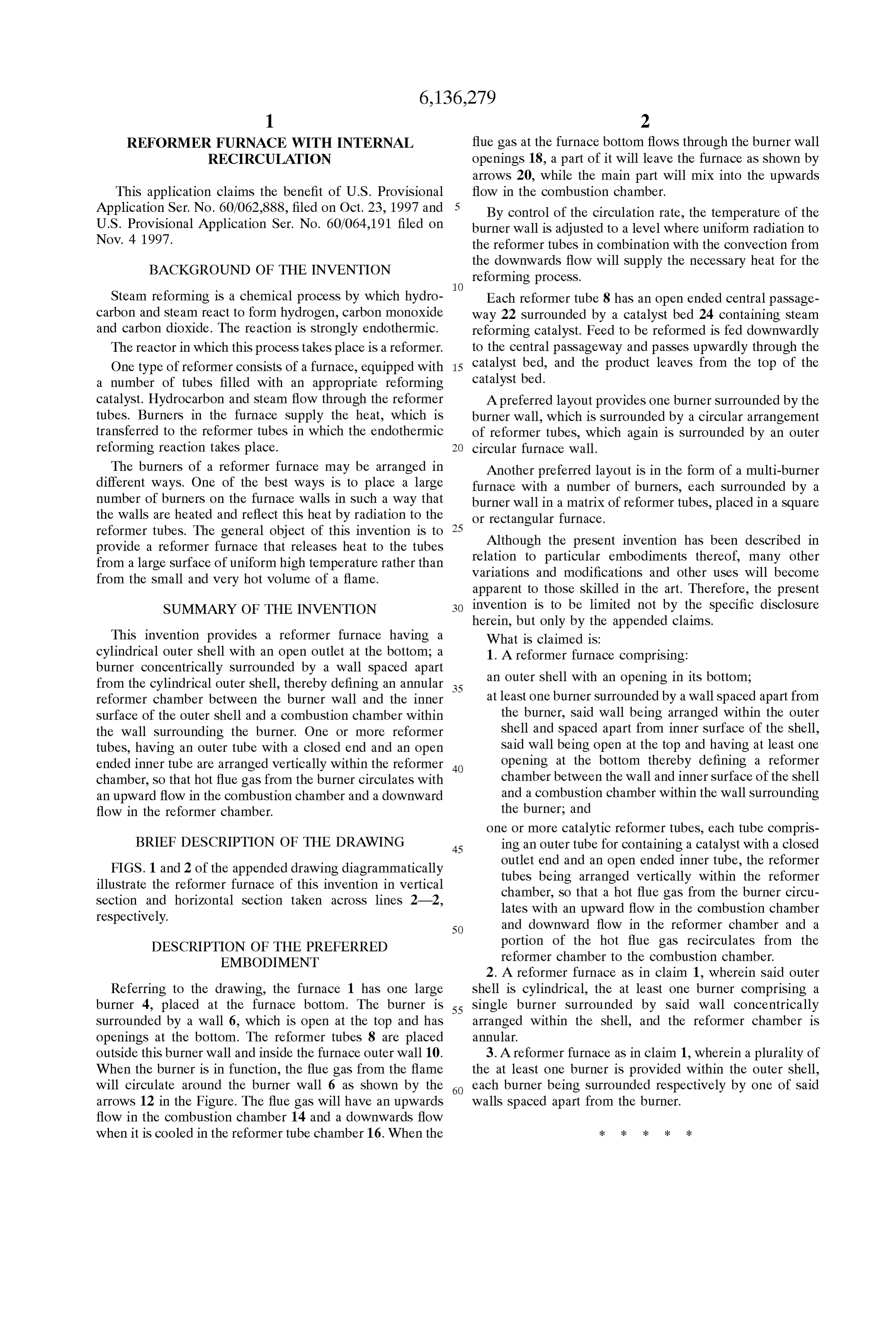
REFORMER FURNACE WITH INTERNAL flue gas at the furnace bottom flows through the burner wall RECIRCULATION openings 18, a part of it will leave the furnace as shown by arrows 20, while the main part will mix into the upwards
This application claims the benefit of U.S. Provisional flow in the combustion chamber. Application Ser. No. 60/062,888, filed on Oct. 23, 1997 and By control of the circulation rate, the temperature of the U.S. Provisional Application Ser. No. 60/064,191 filed on burner wall is adjusted to a level where uniform radiation to Nov. 4 1997. the reformer tubes in combination with the convection from
BACKGROUND OF THE INVENTION
the downwards flow will supply the necessary heat for the reforming process.
Steam reforming is a chemical process by which hydro Each reformer tube 8 has an open ended central passage carbon and Steam react to form hydrogen, carbon monoxide way 22 Surrounded by a catalyst bed 24 containing Steam and carbon dioxide. The reaction is strongly endothermic. reforming catalyst. Feed to be reformed is fed downwardly The reactor in which this process takes place is a reformer. to the central passageway and passes upwardly through the One type of reformer consists of a furnace, equipped with 15 catalyst bed, and the product leaves from the top of the a number of tubes filled with an appropriate reforming catalyst bed.
catalyst. Hydrocarbon and steam flow through the reformer A preferred layout provides one burner surrounded by the tubes. Burners in the furnace Supply the heat, which is burner wall, which is Surrounded by a circular arrangement transferred to the reformer tubes in which the endothermic of reformer tubes, which again is Surrounded by an outer reforming reaction takes place. circular furnace wall.
The burners of a reformer furnace may be arranged in Another preferred layout is in the form of a multi-burner different ways. One of the best ways is to place a large furnace with a number of burners, each Surrounded by a number of burners on the furnace walls in Such a way that burner wall in a matrix of reformer tubes, placed in a Square the walls are heated and reflect this heat by radiation to the or rectangular furnace.
reformer tubes. The general object of this invention is to 25 Although the present invention has been described in provide a reformer furnace that releases heat to the tubes relation to particular embodiments thereof, many other from a large Surface of uniform high temperature rather than variations and modifications and other uses will become from the small and very hot volume of a flame. apparent to those skilled in the art. Therefore, the present SUMMARY OF THE INVENTION invention is to be limited not by the specific disclosure herein, but only by the appended claims.
This invention provides a reformer furnace having a What is claimed is:
cylindrical Outer shell with an open outlet at the bottom; a 1. A reformer furnace comprising: burner concentrically Surrounded by a wall spaced apart from the cylindrical Outer shell, thereby defining an annular 35 an outer shell with an opening in its bottom; reformer chamber between the burner wall and the inner at least one burner Surrounded by a wall spaced apart from Surface of the outer shell and a combustion chamber within the burner, Said wall being arranged within the outer the wall surrounding the burner. One or more reformer shell and Spaced apart from inner Surface of the shell, tubes, having an outer tube with a closed end and an open Said wall being open at the top and having at least one ended inner tube are arranged vertically within the reformer 40 opening at the bottom thereby defining a reformer chamber, So that hot flue gas from the burner circulates with chamber between the wall and inner Surface of the shell an upward flow in the combustion chamber and a downward and a combustion chamber within the wall Surrounding flow in the reformer chamber. the burner; and one or more catalytic reformer tubes, each tube compris
BRIEF DESCRIPTION OF THE DRAWING 45 ing an outer tube for containing a catalyst with a closed FIGS. 1 and 2 of the appended drawing diagrammatically outlet end and an open ended inner tube, the reformer illustrate the reformer furnace of this invention in vertical tubes being arranged vertically within the reformer Section and horizontal Section taken acroSS lines 2-2, chamber, So that a hot flue gas from the burner circu respectively. lates with an upward flow in the combustion chamber 50 and downward flow in the reformer chamber and a
DESCRIPTION OF THE PREFERRED portion of the hot flue gas recirculates from the EMBODIMENT reformer chamber to the combustion chamber. 2. A reformer furnace as in claim 1, wherein Said outer
Referring to the drawing, the furnace 1 has one large shell is cylindrical, the at least one burner comprising a burner 4, placed at the furnace bottom. The burner is 55 Single burner Surrounded by Said wall concentrically Surrounded by a wall 6, which is open at the top and has arranged within the shell, and the reformer chamber is openings at the bottom. The reformer tubes 8 are placed annular.
outside this burner wall and inside the furnace outer wall 10. 3. A reformer furnace as in claim 1, wherein a plurality of When the burner is in function, the flue gas from the flame the at least one burner is provided within the outer shell, will circulate around the burner wall 6 as shown by the 60 each burner being Surrounded respectively by one of Said arrows 12 in the Figure. The flue gas will have an upwards walls Spaced apart from the burner.
flow in the combustion chamber 14 and a downwards flow when it is cooled in the reformer tube chamber 16. When the k k k k k
Provenance
- Collection
- Cited prior art
- Original PDF
- patentimages.storage.googleapis.com →
- Filed
- 1998-10-16
- Pages
- 3
- Method
- pdftotext (the PDF's own text layer) + pdftoppm 300dpi page scans
- Source
- Google Patents bibliographic record
- Granted
- 2000-10-24
- Inventors
- Henrik Otto Stahl; Haldor Topsoe AS
- Transcribed from
- patentimages.storage.googleapis.com →