patent · US5811065
Burner exhaust gas collection assembly for a catalytic reformer
22 September 1998
Page 1 — bibliographic record
United States Patent (19) 11 Patent Number: 5,811,065 Sterenberg (45) Date of Patent: Sep. 22, 1998 54) BURNER EXHAUST GAS COLLECTION 4,661,323 4/1987 Olesen .................................... 422/197 ASSEMBLY FOR A CATALYTIC REFORMER 4,921,680 5/1990 Bonk et al. . 422/197 5,264,008 11/1993 Corrigan ..................................... 48/94 75 Inventor: David J. Sterenberg, Vancouver, 5,470,360 11/1995 Sederquist ................................... 48/94 Canada 5,484,577 1/1996 Buswell et al. ......................... 422/211
FOREIGN PATENT DOCUMENTS
73 Assignee: Ballard Generation Systems Inc.,
Burnaby, Canada WO 97/05947 2/1997 WIPO.
Primary Examiner Hien Tran 21 Appl. No.: 840,027 Attorney, Agent, or Firm McAndrews, Held & Malloy, 22 Filed: Apr. 24, 1997 Ltd.
6 57 ABSTRACT 51) Int. Cl. ......................................................... B01J 8/06 52 U.S. Cl. .......................... 422/198; 422/196; 422/197; A catalytic reformer includes a reformer vessel defining an 422/211; 48/127.9 interior plenum housing at least one reactor tube assembly 58 Field of Search ..................................... 422/197, 211, having a catalyst bed. The reformer also includes a burner 422/204, 205; 48/94, 127.9; 208/134 gas inlet for providing hot burner gas to heat the reactor tubes, and a burner gas outlet. A burner gas guide sleeve is 56) References Cited disposed Substantially coaxially around at least a portion of the reactor tube assembly, defining an annular burner gas
3,926,135 12/1975 De Gregorio ......................... 114/74 R the burner gas guide sleeve to the burner gas outlet. 4,071,330 1/1978 Sederquist ................................... 48/94 4.325,916 4/1982 Worley .................................... 422/197 12 Claims, 4 Drawing Sheets
l, St.
60 S2
Page 2
Drawing sheet — no readable text.
Page 3
Drawing sheet — no readable text.
Page 4
Drawing sheet — no readable text.
Page 5
Drawing sheet — no readable text.
Page 6
BURNER EXHAUST GAS COLLECTION prevent bypass of hot gases around the sleeves. The insu ASSEMBLY FOR A CATALYTIC REFORMER lation thus divides the interior of the vessel into two ple
FIELD OF THE INVENTION In order to improve the heat efficiency of the reformer, the The present invention relates to a burner exhaust gas Seal plate is preferably gas tight So as to prevent any of the collection assembly for catalytic reformers. burner gas from bypassing the sleeves and flowing directly from the primary plenum to the Secondary plenum. Further,
BACKGROUND OF THE INVENTION the Seal plate must be designed So as to accommodate A catalytic reformer converts a fuel Stream, comprising, differential thermal expansions, for example, those arising for example, natural gas, light distillates, methanol, propane, from temperature differences between the reformer wall and naphtha, kerosene, and/or combinations thereof, and water the Seal plate. AS used herein, the term "expansion” refers to Vapor into a hydrogen-rich reformate Stream. In fuel cell dimensional changes caused by heating or cooling a electric power generation Systems employing a catalytic material, and includes a dimensional increases as well as reformer, the hydrogen-rich reformate Stream is generally 15 dimensional decreases (contractions). Failure to adequately purified, for example, by passing through a hydrogen Sepa accommodate differential thermal expansion can in extreme rator or a shift reactor and a carbon monoxide Selective cases cause the Seal plate to buckle and fail. In less extreme oxidizer, prior to being used as the fuel Stream delivered to cases, differential expansion can break the Seal between the the anode of an electrochemical fuel cell. In the reforming Seal or plate and the reformer vessel wall or the reactor tubes sleeves. Differential thermal expansion is often further process, the fuel Stream is typically percolated through one or more catalyst beds contained within a reformer vessel. exacerbated ponents may because the Seal plate and other reformer com be fabricated of different materials and as a
For hydrocarbon fuels. Such as, for example, natural gas, the catalytic conversion process is normally carried out at result have different coefficients of thermal expansion. elevated catalyst bed temperatures in the range of about For reformerS having a Single reactor tube, Such as, for 1200° F to about 1600°F. Such elevated temperatures are 25 example, that shown in FIG. 1 of U.S. Pat. No. 5,484.577 typically generated by one or more burners, typically incor previously incorporated herein by reference, designing a porated in the reformer vessel. Seal plate tolerant of differential thermal expansion is more A typical catalytic hydrocarbon reformer is described and Straightforward than for reformerS having multiple reactor illustrated in U.S. Pat. No. 5,484,577, which is incorporated tubes, such as, for example, that shown in FIG.3 of U.S. Pat. herein by reference in its entirety. This type of reformer No. 5,484,577. In the latter design, complex seal arrange typically comprises a Substantially cylindrical closed pres ments and geometries are used to accommodate differential sure vessel as the reformer shell, with thermally insulated thermalFor expansion while maintaining a pressure tight Seal.
example, the seal plate disclosed in U.S. Pat. No.
interior walls. At least one reactor tube assembly is disposed within the vessel, each reactor tube typically containing an 4,921,680 employs a flexible bellows connection between outer annular catalyst bed and an inner concentric gas return 35 the seal plate and the reformer wall. The bellows can tube. The fuel gas is directed through the outer catalyst bed reportedly tial thermal accommodate movements arising from differen expansions. Seal plates employing complex and the resulting reformate Stream is directed in an opposing geometries and many components may be expensive and or counterflow direction through the inner portion of the complicated to build and install in the reformer vessel. tube returning heat to the incoming gas.
In most reformers of this type, with catalyst-containing 40 In the present design a burner exhaust gas collection reactor tubes disposed in a preSSure vessel, the hot burner assembly is used to collect the burner gas from the annular gas is generated at a burner, generally within the reformer passages between the sleeves and reactor tubes, and to direct vessel, and accumulates in a primary (typically, upper) itrequired. to the outlet. A Seal plate, dividing the plenum, is not plenum within the vessel, contacting and heating the outer
Surface of the reactor tubes. In preferred reformer designs, 45 SUMMARY OF THE INVENTION the hot burner gas is directed through a cylindrical sleeve
Surrounding at least the lower portion of each reactor tube, A catalytic reformer comprises a reformer vessel defining So that the hot burner gas travels in close contact with the an interior plenum, and at least one reactor tube assembly reactor tubes and effective heat transfer occurs. Thus, hot disposed within the plenum. The at least one reactor tube burner gas from the primary plenum flows through a narrow, 50 assembly comprises a catalyst bed. The reformer further annular passage between the internal wall of the Sleeve and comprises a burner gas inlet for delivering hot burner gas to the external wall of each reactor tube, and into a Secondary the interior plenum, a burner gas outlet, and a burner gas (lower) plenum, from which it is discharged. A Seal plate guide sleeve disposed Substantially coaxially around at least forms a barrier across the width of the reformer vessel and a portion of the reactor tube assembly, defining an annular around the individual reactor tube sleeves, So that the 55 burner gas passage. A burner exhaust gas collection assem primary and Secondary plenum are fluidly connected only bly connects the burner gas guide sleeve to the burner gas via the annular passages, and therefore the hot burner gas outlet.
must pass between a sleeve and reactor tube to exit the The burner exhaust gas collection assembly is an inte reformer vessel via the Secondary plenum. In down-fired grated assembly of piping or interconnected passages. Inside reformer designs the Seal plate is typically located at or near 60 the burner exhaust gas collection assembly the burner gas is the end of the reactor tubes farthest from the burner. The not in direct contact with the interior walls of the reformer. burner gas typically then exits the Secondary plenum of the In preferred embodiments at least a portion of the burner reformer vessel through a burner gas outlet. exhaust gas collection assembly is compliant, to accommo Seal plates are generally described and disclosed in U.S. date differential thermal expansion of the reformer compo Pat. No. 4,921,680 and U.S. Pat. No. 5,264,008. In U.S. Pat. 65 nentS.
No. 5,470,360, no Seal plate is used, the passages around the In an embodiment of a catalytic reformer with a single sleeves being instead packed with insulation and Sealed to reactor tube assembly disposed within the plenum, the
Page 7
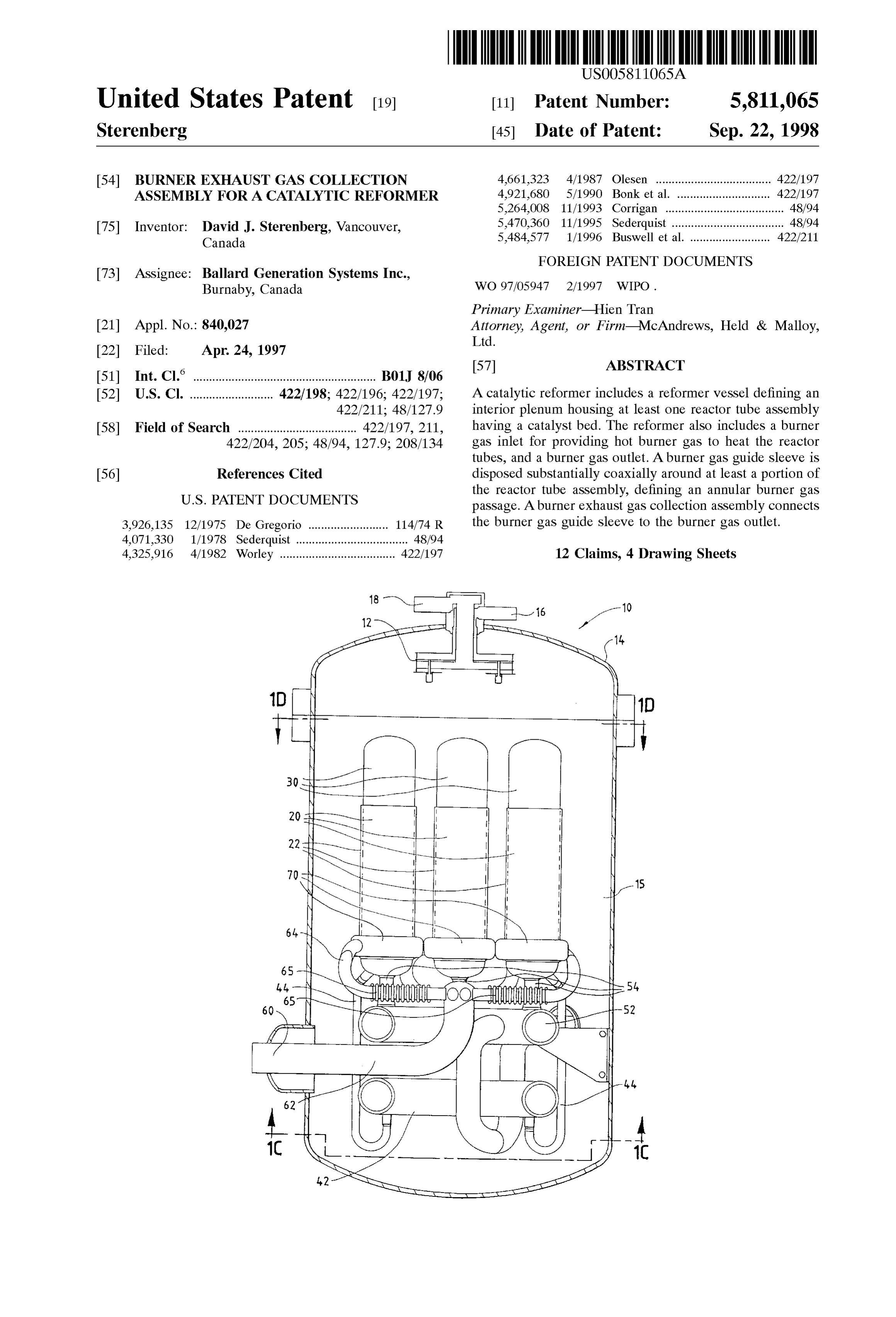
burner exhaust gas collection assembly comprises a conduit FIG. 1A is a side sectional view taken in the direction of connecting the burner gas guide Sleeve to the burner gas arrows A-A in FIGS. 1C and 1D.
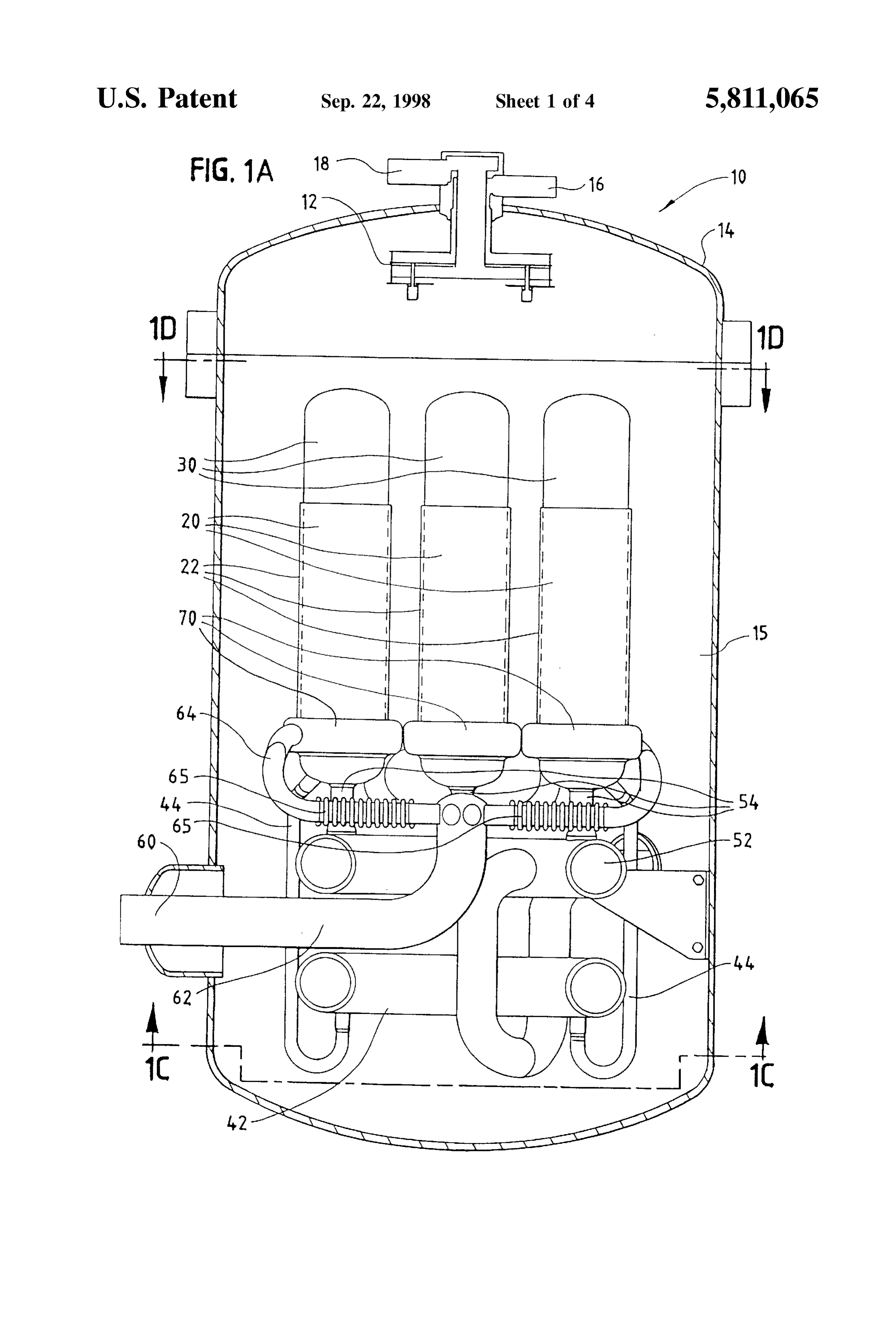
outlet. In preferred embodiments, the conduit is welded to FIG. 1B is a side sectional view taken in the direction of the burner gas guide sleeve and to the burner gas outlet. arrows B-B in FIGS. 1C and 1D.
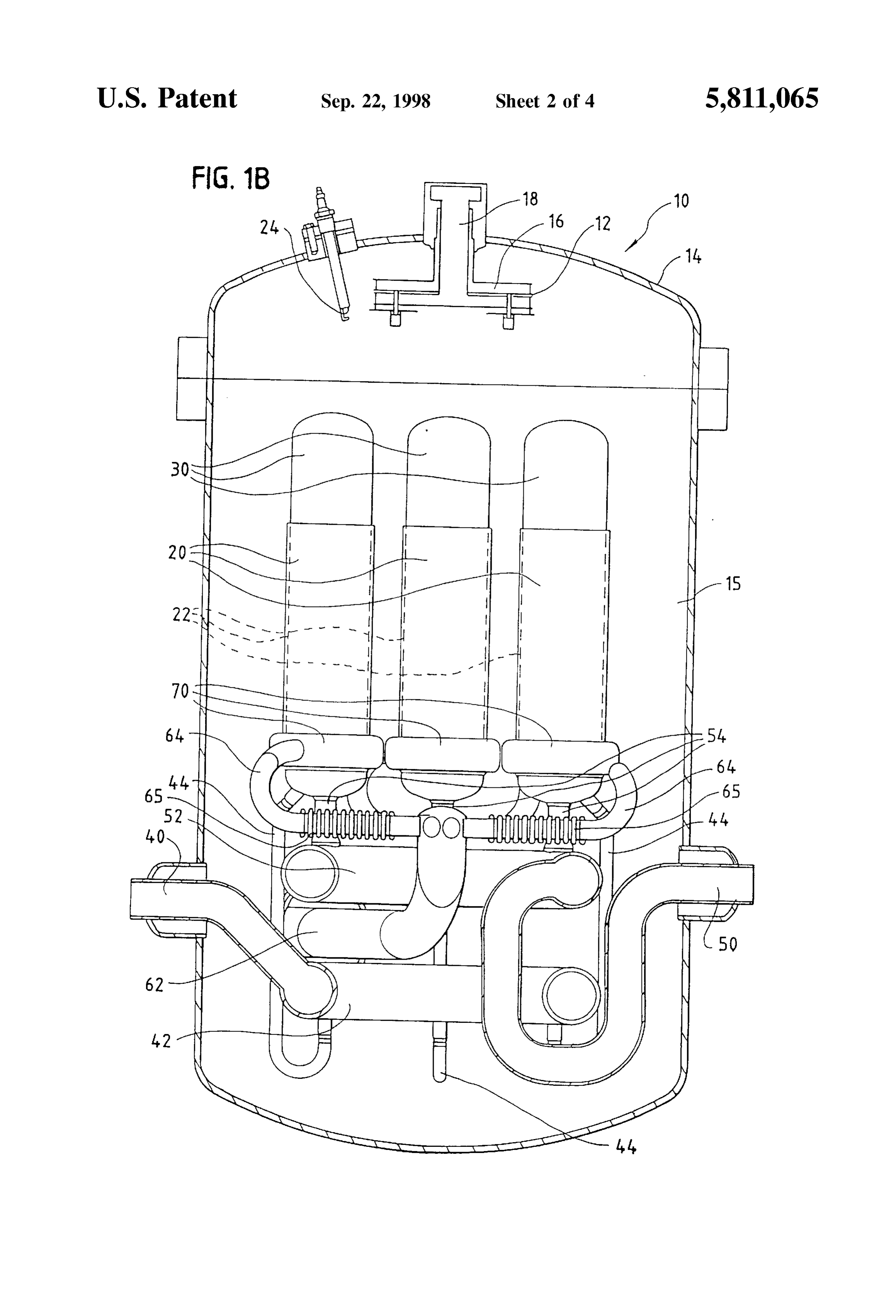
Optionally, the conduit could be cast in a single piece. Such FIG. 1C is a bottom sectional view taken in the direction a unitary cast Structure may also, optionally, include reactant of arrows C-C in FIG. 1A.
and product Stream conduits for directing those Streams to and from the reactor tube assembly, respectively. FIG. 1D is a top sectional view taken in the direction of In an embodiment of a catalytic reformer with a plurality arrows D-D in FIG. 1A.
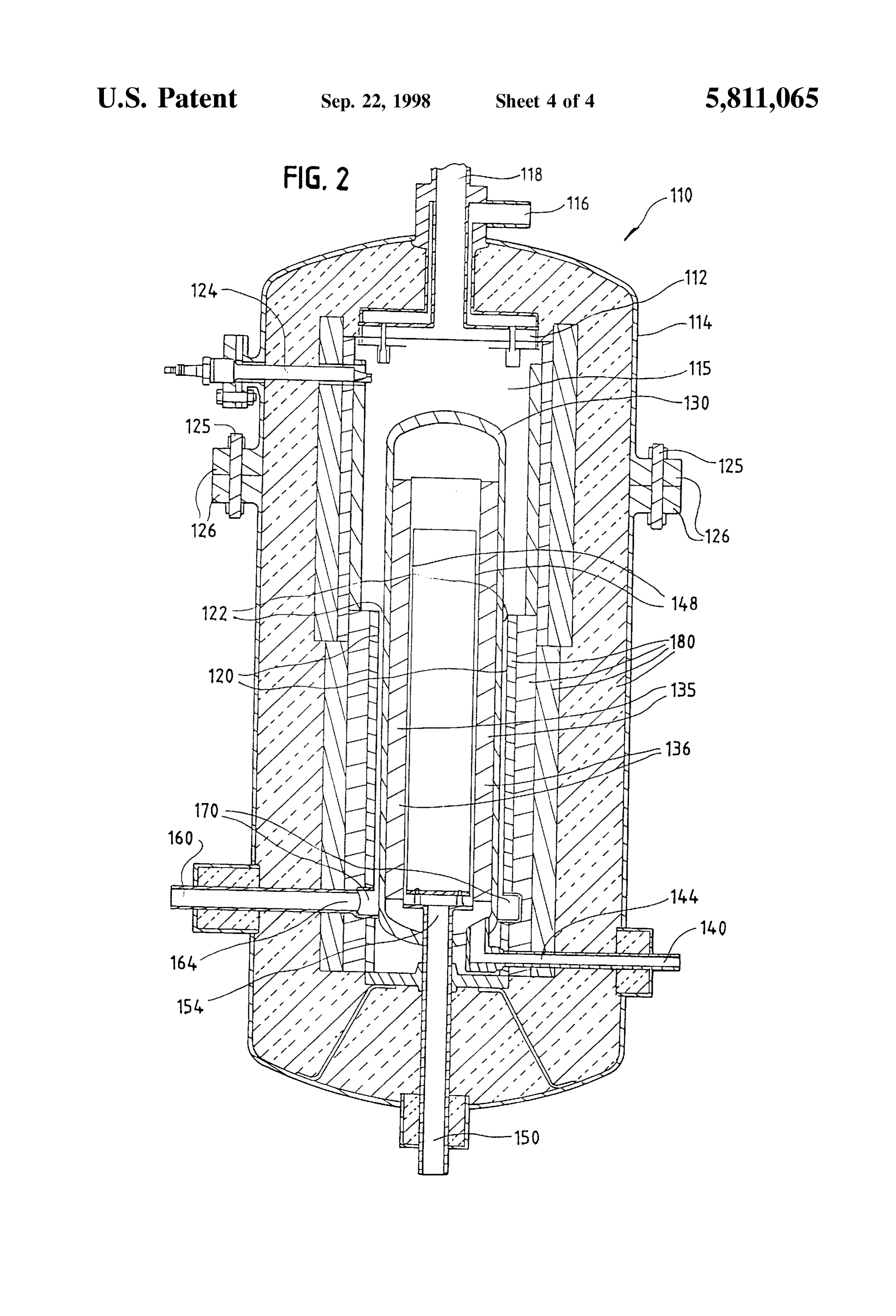
of reactor tube assemblies disposed within the plenum, the FIG. 2 is a detailed side sectional view of a catalytic burner exhaust gas collection assembly comprises a burner hydrocarbon Steam reformer with a single reactor tube and exhaust gas manifold connected to the burner gas outlet, and a burner exhaust gas collection assembly. individual conduits connecting each of the burner gas guide sleeves to the burner exhaust gas manifold. Thus, the burner DETAILED DESCRIPTION OF THE gas is separately ducted from each annular passage to a 15 PREFERRED EMBODIMENTS common collection manifold from which it is discharged Turning first to FIGS. 1A and 1B, a catalytic hydrocarbon from the vessel at the burner gas outlet. Preferably the reformer conduits are compliant to accommodate thermal expansion. the top of10a includes a multi-nozzled burner 12 located at substantially cylindrical reformer vessel 14.
For example, at least a portion of the conduit wall may be Burner 12 is supplied with a fuel stream through burner fuel corrugated. In preferred embodiments the conduits are Stream inlet 16, and an oxidant Stream through burner welded to the burner gas guide sleeves and to the burner oxidant stream inlet 18. The burner fuel and oxidant mixture exhaust gas manifold, and the burner exhaust gas manifold is ignited at burner 12 by a Spark generator located at the end is preferably welded to the burner gas outlet. The conduits of an ignition mechanism or spark plug 24 (visible in FIG. may each, optionally comprise a collection collar extending 1B). The mixture is combusted outwardly from the burner gas guide Sleeve and circum 25 hot burner gas stream in the interior at the burner 12 to create a Scribing an end portion of the reactor tube assembly. volume or plenum 15 In Some embodiments the burner exhaust gas manifold is defined by the vessel 14. The reformer vessel 14 is typically cast as a Single piece, which is preferably welded to the formed in several pieces which are welded or bolted together at flanged connections. Typically the reformer vessel is lined burner gas guide sleeves and to the burner gas outlet. Such with multiple layers of thermally insulating material (not a unitary cast Structure may also, optionally, include the shown), which fill a large portion of the plenum 15. reactant and product Stream manifolds. In further embodiments, Substantially the entire burner exhaust gas The reformer vessel 14 houses a plurality of reactor tubes collection assembly, including the burner exhaust gas mani 30, A each containing a catalyst bed (shown as 135 in FIG. 2).
reactant fuel stream enters reactant fuel Stream manifold fold and conduits, may be cast as a Single piece, which is 42 in the reformer vessel 14 at a reactant fuel stream inlet 40 preferably then welded to the burner gas guide sleeves and 35 the burner gas outlet. Such a unitary cast Structure may also, (visible in FIG. 1B). From the manifold it is directed to the optionally, include reactant and product Stream manifolds catalyst beds in the reactor tubes 30 via individual fuel Stream conduits 44. The product reformate Stream from each and conduits for directing Streams to and from the reactor reactor tube assemblies. tube is directed to a reformate Stream collection In another embodiment, a catalytic reformer with a plu 40 manifold 52 via individual reformate stream conduits 54, rality of reactor tube assemblies disposed within the plenum and exits the reformer vessel 14 at reformate stream outlet has a plurality of burner gas outlets, and the burner exhaust 50 (visible in FIG. 1B).
gas collection assembly comprises individual conduits con In multi-tube reformers, such as that illustrated in FIGS. necting each of the guide sleeves to one of the outlets. 1A-D, the reactor tube assemblies are preferably arranged in Thus,the burner gas is separately ducted from each annular 45 concentric tiers, rows or rings.
passage to an individual burner gas outlet. The lower portion of each reactor tube 30 has a burner gas The hot burner gas may be generated within the reformer guide sleeve 20 Spaced Substantially coaxially around it, vessel, for example the burner gas inlet may comprise a defining an annular burner gas passage 22 (indicated by burner disposed within the plenum. Alternatively, the hot broken lines) between the outer wall of the reactor tube 30 burner gas may be Supplied from a Source external to the 50 and the inner wall of the sleeve 20. The hot burner gas reformer vessel, entering the vessel at the burner gas inlet. generated at burner 12 passes through the annular passages More than one burner gas inlet may be provided. The 22 and is collected at the base of each reactor tube 30 and location of the burner gas inlet or inlets is a matter of design directed via individual burner exhaust gas conduits 64 to a choice. For example, the reformer could be an up-fired or common burner exhaust gas manifold 62, exiting the down-fired reformer. In embodiments illustrated below a 55 reformer vessel 14 at a burner gas outlet 60 (visible in FIG. down-fired centrally located burner is housed within the 1A). Because the burner gas outlet 60 is fluidly connected to reformer vessel. the plenum 15 only via burner exhaust gas manifold 62, Preferably the reformer vessel is substantially cylindrical. conduits 64 and annular passages 22, Substantially all of the The conduits and manifolds described above need not be hot burner gas is forced to pass through the annular passages unitary Structures. They may each comprise an assembly of 60 22, thus heating the reactor tubes 30. The annular burner gas interconnected parts. passages may optionally include baffles, channels or other Such elements to direct flow and/or induce turbulent flow.
BRIEF DESCRIPTION OF THE DRAWINGS The burner exhaust gas conduits 64 may comprise Several FIGS. 1A, 1B, 1C and 1D are sectional views of a interconnected Sections. For example, in the illustrated catalytic hydrocarbon Steam reformer with a plurality of 65 embodiment, burner exhaust gas conduits 64 comprise a reactor tubes and a burner exhaust gas collection assembly collection collar 70, at the base of each sleeve 20, a curved comprising a burner exhaust gas manifold. elbow section and a corrugated section 65. The burner
Page 8
S 6 exhaust gas conduit 64 from each reactor tube 30 is designed defining an annular burner gas passage 122. The hot burner to accommodate or tolerate thermal expansion. For example, gas generated at burner 112 passes through the annular the burner exhaust gas conduits 64 depicted in FIGS. 1A and passage 122 and is collected at the base of reactor tube 130 1B are designed to accommodate thermal expansion as a and directed via burner exhaust gas conduit 164 to burner result of a corrugated section 65 in the conduits 64. If at least 5 gas outlet 160. Because the burner gas outlet 160 is fluidly a portion of the conduit 64 is compliant, it may accommo connected to the plenum 115 only via burner exhaust gas date differential thermal expansion and attendant movement conduit 164 and annular passage 122, Substantially all of the of reformer parts within the reactor tube assembly. Tolerance hot burner gas is forced to pass through the annular passage to differential thermal expansion be introduced in other 122, thus heating the reactor tube 130.
ways, for example, by extending the length of conduits 64, or by configuring the components So that the Stresses caused gasInconduit the embodiment illustrated in FIG. 2, burner exhaust 164 comprises an annular collection collar 170 by thermal expansion are mitigated. at the base of sleeve 120.
Preferably the various interconnected manifold and con Typically the reformer vessel is lined with a thermally duit components in FIGS. 1A, 1B, 1C and 1D are welded insulating material. AS shown in FIG. 2, typically multiple together. For example, preferably burner gas conduit 64 is 15 layers of insulation 180 are employed, which fill a large welded at one end to burner gas guide Sleeve 22, and at the portion of the plenum 115.
other end to burner exhaust gas manifold 62, and manifold Again, various fabrication and construction techniques 62 is preferably welded to burner gas outlet 60. Similarly the may be used to assembly the various components, including Sub-components making up each of these components 62 welding or casting, as described above. and 64 are preferably assembled by welded joints. In another The catalytic hydrocarbon reformers illustrated in FIGS. fabrication approach, manifolds 42, 52 and 62 could all be 1 and 2 are particularly Suitable for Steam reforming of cast in a unitary Structure or block, which could be con natural gas.
nected to conduits 44, 54 and 64 and to inlet 40 and outlets 50 and 60, for example, by welding. Further still, manifolds The present reformer burner exhaust gas collection 42, 52 and 62, and conduits 44, 54, and 64 may be cast in 25 burner gasobviates assembly the need for a Seal plate to force the through the annular passages by forming a Seal a unitary Structure. In this case the unitary Structure may be
Sufficiently robust to withstand any Stresses arising from acroSS the width of the reformer vessel, dividing the plenum. differential thermal expansion, without the burner exhaust Instead the burner gas is ducted from each annular passage gas collection assembly comprising a compliant portion. to a burner gas outlet.
FIG. 1C illustrates the configuration of the fluid stream While particular elements, embodiments and applications manifolds and conduits in further detail. Reactant fuel of the present invention have been shown and described, it Stream manifold 42, which includes a toroidal shaped will be understood, of course, that the invention is not Section, interconnects reactant fuel Stream inlet 40 to Six limited thereto Since modifications may be made by those individual fuel stream conduits 44. Reformate stream col skilled in the art, particularly in light of the foregoing lection manifold 52 (the toroidal section of which is 35 teachings. It is therefore contemplated by the appended obscured in FIG. 1C by manifold 42) is connected to claims to cover Such modifications as incorporate those reformate stream outlet 50. Six individual burner exhaust features which come within the Spirit and Scope of the gas conduits 64 are centrally connected to a common burner invention. What is claimed is:
exhaust gas manifold 62, which in turn is connected to 1. A catalytic reformer comprising: burner gas outlet 60, as shown in FIGS. 1C and 1D. 40
FIG. 2 shows a catalytic hydrocarbon reformer 110, with (a) a reformer vessel having interior walls defining a a single reactor tube 130. Reformer 110 is similar in design Single interior plenum;
to reformer 10 of FIGS. 1A, 1B, 1C and 1D, and includes a (b) at least one reactor tube assembly disposed within Said multi-nozzled burner 112, Supplied with a fuel stream plenum, Said at least one reactor tube assembly com through burner fuel Stream inlet 116, and an oxidant Stream 45 prising a catalyst bed;
through burner oxidant stream inlet 118. The burner fuel and (c) a burner gas inlet for delivering burner gas to said oxidant mixture is ignited at burner 112 by a Spark generator interior plenum;
124, and is combusted at the burner 112 to create a hot (d) a burner gas outlet;
burner gas stream in the interior volume or plenum 115 (e) a burner gas guide sleeve disposed Substantially coaxi defined by the substantially cylindrical reformer vessel 114. 50 ally around at least a portion of each of Said at least one As shown in FIG. 2, the reformer vessel is typically formed reactor tube assembly defining an annular burner gas in several pieces which are secured together by bolts 125 at passage, flanged connections 126. (f) a burner exhaust gas collection assembly comprising a A reactant fuel Stream enters the reformer vessel 114 at a conduit extending from and Sealed to Said burner gas reactant fuel Stream inlet 140, and is directed via reactant 55 guide Sleeve, Said assembly fluidly connecting Said fuel stream conduit 144 to an annular catalyst bed 135 in the burner gas passage to Said burner gas outlet Such that reactor tube 130. The reactant stream passes in contact with burner gas exiting Said passage does not contact Said catalyst pellets 136 contained in the catalyst bed 135, and is interior plenum.
converted into a hydrogen-rich reformate Stream. The prod 2. The catalytic reformer of claim 1 wherein said at least uct reformate stream exits the catalyst bed 135 toward the 60 a portion of Said burner exhaust gas collection assembly is top of reactor tube 130 and is directed in a counterflow compliant.
configuration to the bottom of reactor tube 130 through an 3. The catalytic reformer of claim 1 wherein said at least inner concentric annular gas return tube 148. The reformate one reactor tube assembly is a Single reactor tube assembly stream is then directed to the reformate stream outlet 150 via disposed within Said plenum.
reformate stream conduit 154. 65 4. The catalytic reformer of claim 1 wherein said at least The lower portion of reactor tube 130 has a burner gas one reactor tube assembly is a plurality of reactor tube guide sleeve 120 Spaced Substantially coaxially around it, assemblies.
Page 9
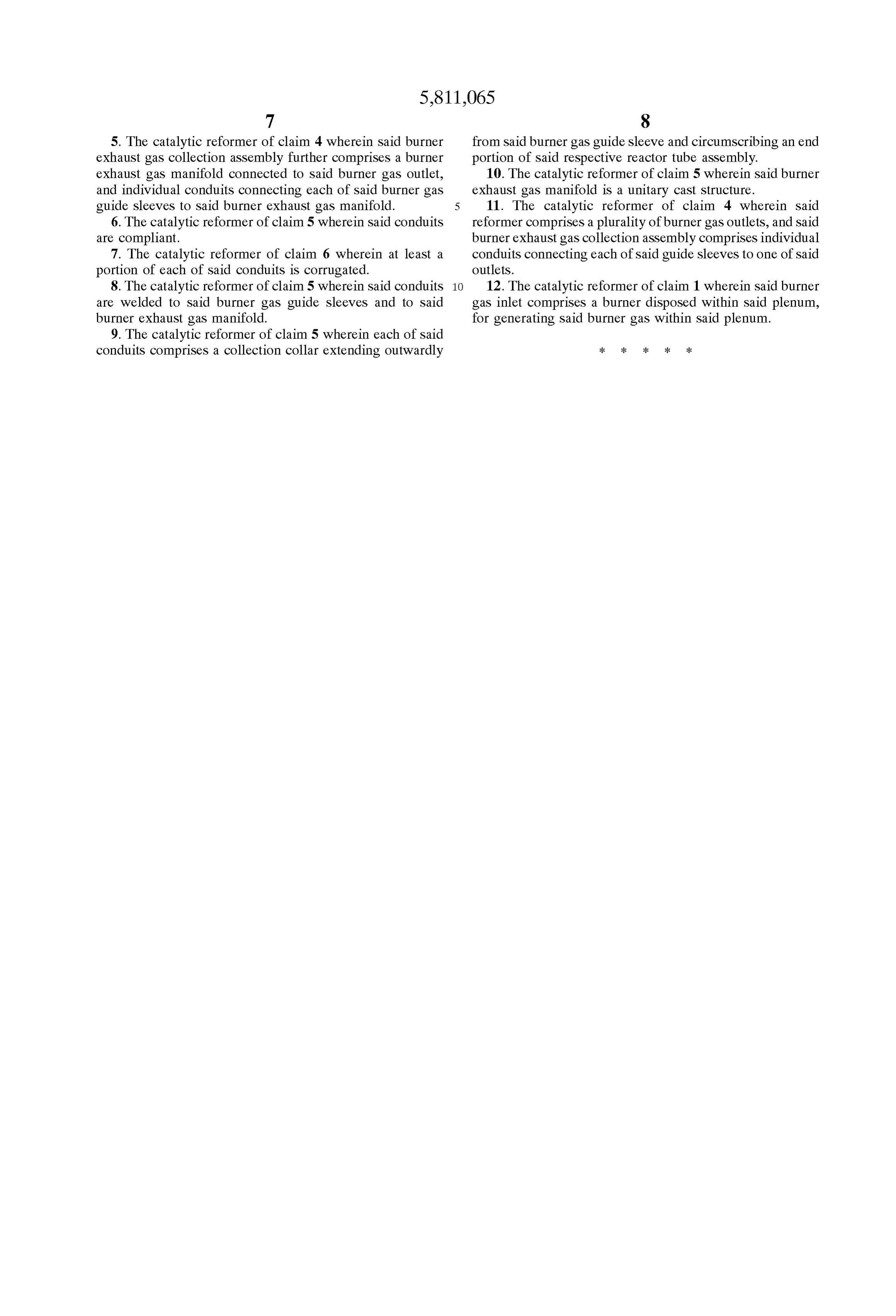
5. The catalytic reformer of claim 4 wherein said burner from Said burner gas guide sleeve and circumscribing an end exhaust gas collection assembly further comprises a burner portion of Said respective reactor tube assembly. exhaust gas manifold connected to Said burner gas outlet, 10. The catalytic reformer of claim 5 wherein said burner and individual conduits connecting each of Said burner gas exhaust gas manifold is a unitary cast Structure. guide sleeves to Said burner exhaust gas manifold. 11. The catalytic reformer of claim 4 wherein said 6. The catalytic reformer of claim 5 wherein said conduits reformer comprises a plurality of burner gas outlets, and Said are compliant. burner exhaust gas collection assembly comprises individual 7. The catalytic reformer of claim 6 wherein at least a conduits connecting each of Said guide sleeves to one of Said portion of each of Said conduits is corrugated. outlets.
8. The catalytic reformer of claim 5 wherein said conduits 12. The catalytic reformer of claim 1 wherein said burner are welded to Said burner gas guide sleeves and to Said gas inlet comprises a burner disposed within Said plenum, burner exhaust gas manifold. for generating Said burner gas within Said plenum. 9. The catalytic reformer of claim 5 wherein each of said conduits comprises a collection collar extending outwardly k k k k k
Provenance
- Collection
- Cited prior art
- Original PDF
- patentimages.storage.googleapis.com →
- Filed
- 1997-04-24
- Pages
- 9
- Method
- pdftotext (the PDF's own text layer) + pdftoppm 300dpi page scans
- Source
- Google Patents bibliographic record
- Granted
- 1998-09-22
- Inventors
- David J. Sterenberg; Ballard Generation Systems Inc
- Transcribed from
- patentimages.storage.googleapis.com →