patent · US20040035401A1
Hydrogen powered scooter
26 February 2004
Page 1 — bibliographic record
(19) United States (12) Patent Application Publication (10) Pub. No.: US 2004/0035401A1
Ramachandran et al. (43) Pub. Date: Feb. 26, 2004 (54) HYDROGEN POWERED SCOOTER Publication Classification
(76) Inventors: Subramanian Ramachandran, Milton, (51) Int. Cl." ...................................................... FO2B 43100 WA (US); Philip Sievers, Detroit, MI (52) U.S. Cl. .............................................................. 123/527 (US); Eugene Kurlonko, Lapeer, MI
(US); Krishna Sapru, Troy, MI (US);
Zhaosheng Tan, Troy, MI (US); (57) ABSTRACT
Stanford R. Ovshinsky, Bloomfield
Hills, MI (US) A Scooter powered by a hydrogen powered internal com Correspondence Address: bustion engine fueled by a throttled stream of air into which ENERGY CONVERSION DEVICES, INC. a controlled amount of hydrogen is injected. A hydrogen fuel 2956 WATERVIEW DRIVE control System is used to control the amount of hydrogen ROCHESTER HILLS, MI 48309 (US) injected into the throttled air Stream using multiple param eters. The amount of hydrogen present in the hydrogen (21) Appl. No.: 10/227,764 Storage unit is monitored using an on-board hydrogen fuel measurement System utilizing a microcontroller and mul (22) Filed: Aug. 26, 2002 tiple Sensors.
Page 2
Drawing sheet — no readable text.
Page 3
Drawing sheet — no readable text.
Page 4
Drawing sheet — no readable text.
Page 5
Drawing sheet — no readable text.
Page 6
Drawing sheet — no readable text.
Page 7
Patent Application Publication Feb. 26, 2004 Sheet 6 of 13 US 2004/0035401A1 Update
EEPROM for annount of hydrogen left in the storage light Red LED.
Get puts from three put purs for tuft Red and Offee fadessure drop across once Amber LED Off
Gas Pressure, Gas Tepeatre
Calcadiate wohne of hydrogen used for a specific tana interwabased or the average flow Figure 7 increment wolume of hydrogen used aid decrewer the wounta of hydrogen left by the Woturne of hydrogen used i? a specific time a thou?nt of hydrogen left
Page 8
Drawing sheet — no readable text.
Page 9
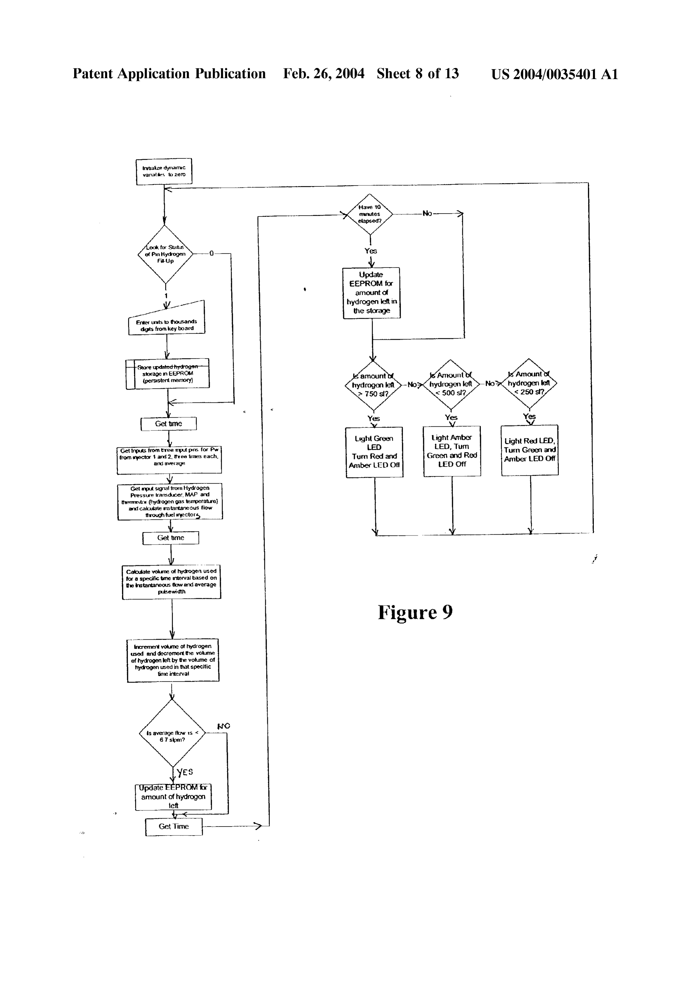
Patent Application Publication Feb. 26, 2004 Sheet 8 of 13 US 2004/0035401A1 thasize dynamic warates to zero
Update
EEPROM for amount of hydrogen left in the storage
Light Red LFD,
Get trp its from tree putpins for Pw LED Tun Green and from rector 1 and 2, three times each. Turn Red and Ambe EDOff
Get input signal fron Hydrogen Pressure transducer, MAP and themesto (hydrogen gas temperature and cakcudate statarteous flow through fuel yector
Calculate wokme of hydrogen used for a specific time interval based on the stantaneous flow and average pulsewidth
Figure 9 increment volume of hydrogen used and decrement the volume of hydrogen left by the volume of hydrogen used in that specific time intervash ls average flow is <
Page 10
Drawing sheet — no readable text.
Page 11
Drawing sheet — no readable text.
Page 12
Drawing sheet — no readable text.
Page 13
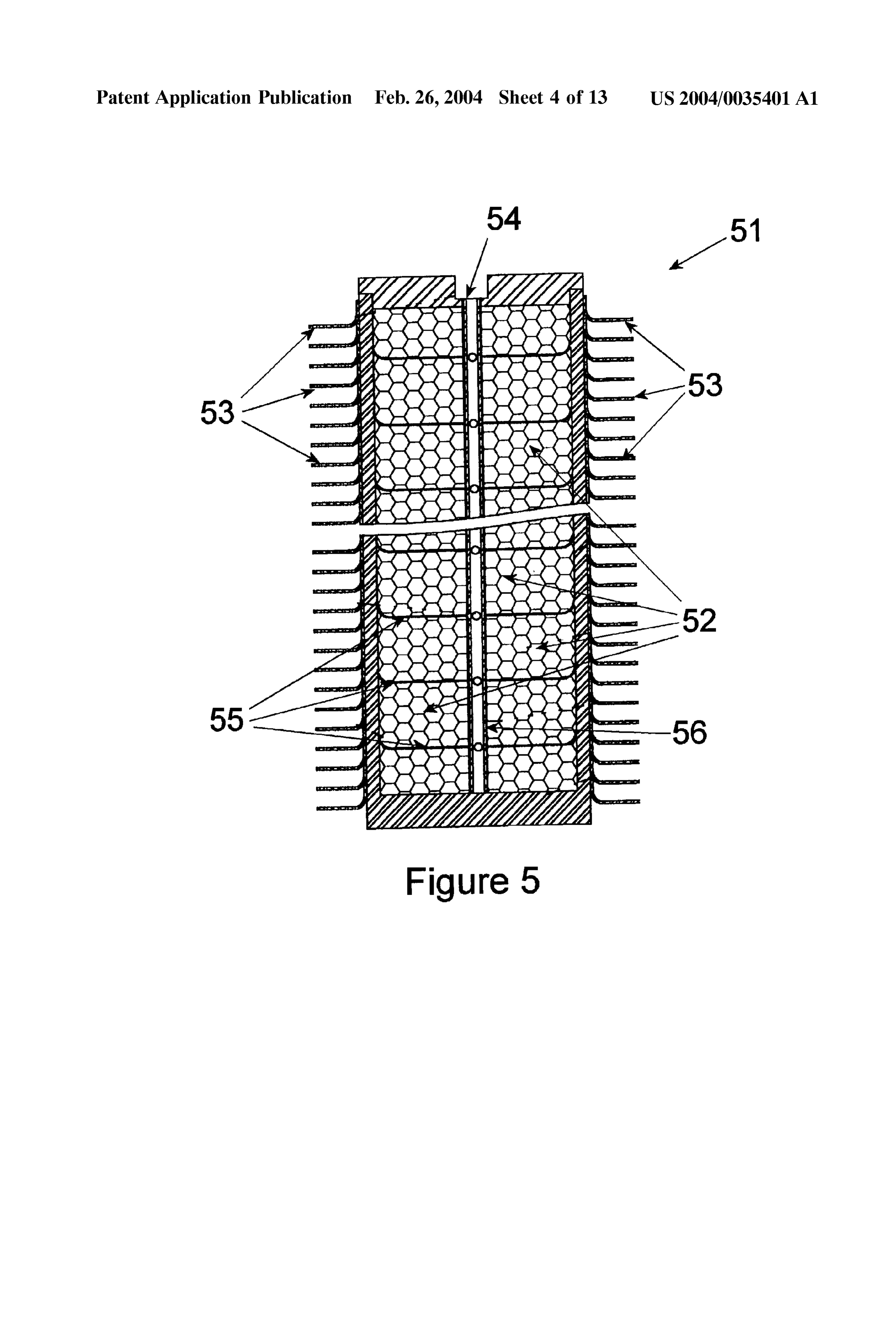
Drawing sheet — no readable text.
Page 14
Drawing sheet — no readable text.
Page 15
US 2004/0035401A1 Feb. 26, 2004
HYDROGEN POWERED SCOOTER biggest chemicals firm, even declared that it would volun tarily reduce its emissions of greenhouse gases to 35% of
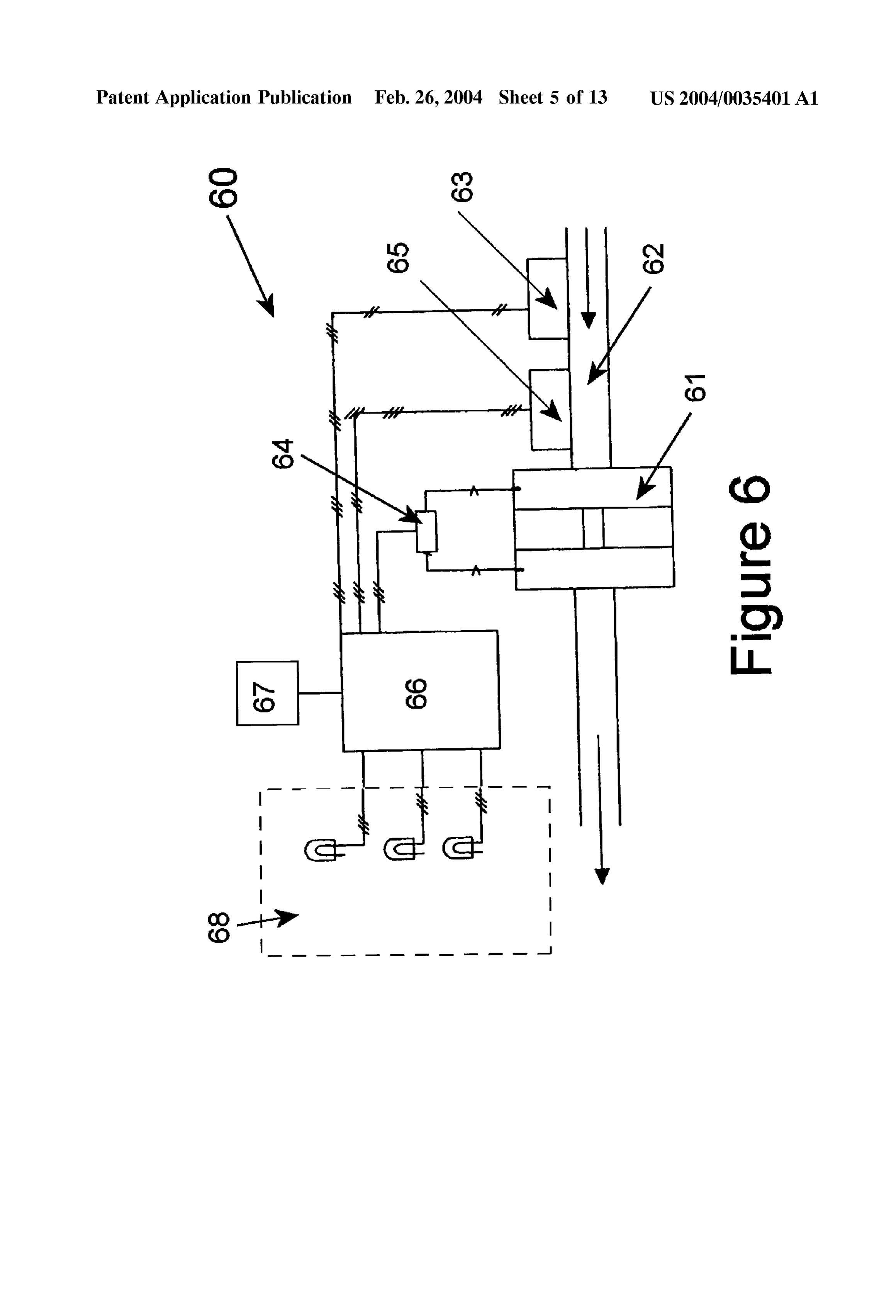
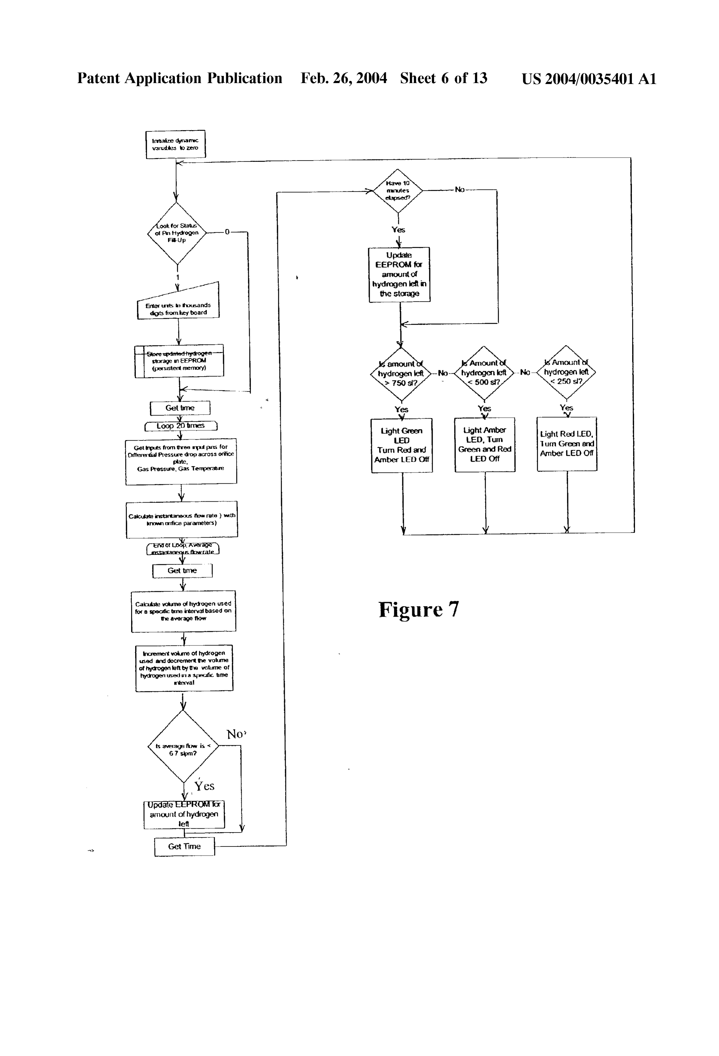
FIELD OF THE INVENTION their level in 1990 within a decade. The automotive industry, 0001. The present invention relates generally to a low which is a Substantial contributor to emissions of greenhouse emission hydrogen powered Scooter. More particularly, the gases and other pollutants (despite its vehicular specific present invention relates to a Scooter powered by a hydrogen reductions in emissions), has now realized that change is powered internal combustion engine with electronically necessary as evidenced by their electric and hybrid vehicles. controlled fuel injector and on-board metal hydride Storage 0006 Hydrogen is the “ultimate fuel.” In fact, it is with fuel gauge. considered by most to be “THE” fuel for the next millen nium, and, it is inexhaustible. Hydrogen is the most plentiful
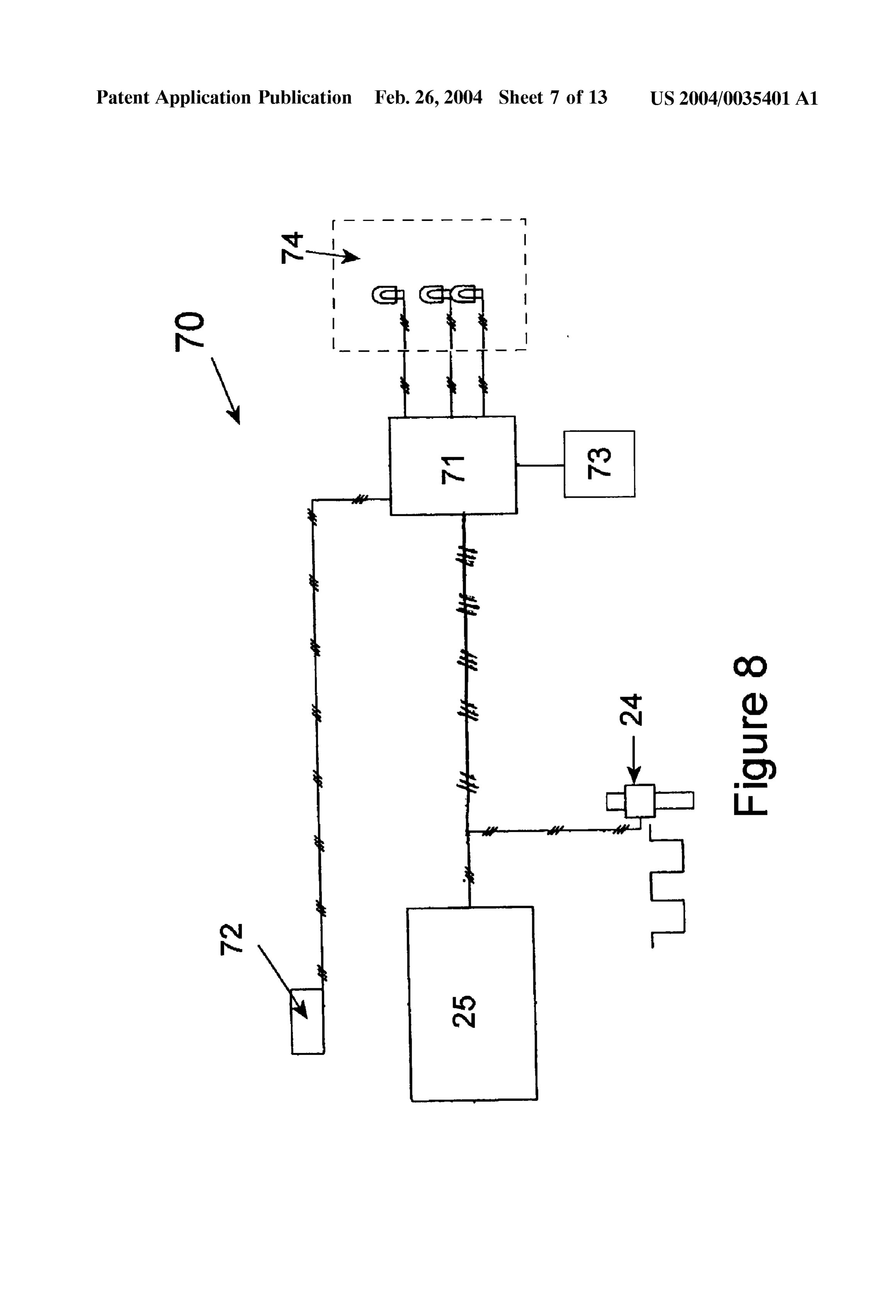
BACKGROUND element in the universe (over 95%) and was the first element created by the "Big-Bang.'Hydrogen can provide an inex 0002. As the world's population expands and its haustible, clean Source of energy for Our planet which can be economy increases, the atmospheric concentrations of car produced by various processes which split water into hydro bon dioxide are warming the earth causing climate change. gen and oxygen. The hydrogen can be Stored and transported However, the global energy System is moving Steadily away in Solid State form. The instant patent application makes it from the carbon-rich fuels whose combustion produces the possible to create a complete generation/storage/transporta harmful gas. Experts Say atmospheric levels of carbon tion/delivery System for Such a hydrogen based economy. dioxide may be double that of the pre-industrial era by the For example, economical, lightweight, triple-junction amor end of the next century, but they also say the levels would phous Silicon Solar cells (an invention pioneered by Stanford be much higher except for a trend toward lower-carbon fuels R. Ovshinsky, one of the instant inventors) Such as those set that has been going on for more than 100 years. Further forth in U.S. Pat. No. 4,678,679, (the disclosure of which is more, fossil fuels cause pollution and are a causative factor herein incorporated by reference) can be readily disposed in the Strategic military Struggles between nations. adjacent a body of water, where their inherently high open 0.003 For nearly a century and a half, fuels with high circuit Voltage can be used to dissociate water into its amounts of carbon have progressively been replaced by constituent gases, and collect the hydrogen So produced. those containing Smaller and Smaller amounts of carbon. Also, by placing these high efficiency Solar panels on nearby First Wood, which is high in carbon, was eclipsed in the late farms, in water, or on land. Electricity can be generated to 19" century by coal, which contains less carbon. Then oil, transport and pump the hydrogen into metal hydride Storage with a lower carbon content still, dethroned "King Coal' in beds that include the inventive metal hydride alloys dis the 1960's. Now analysts say that natural gas, lighter still in closed herein. The ultra-high capacities of these alloys allow carbon, may be entering its heyday, and that the day of this hydrogen to be stored in solid form for transport by hydrogen-providing a fuel with no carbon at all-may at barge, tanker, train or truck in Safe, economical form for last be about to dawn. As a result, experts estimate the ultimate use. Energy is the basic necessity of life and World's economy today burns less than two-thirds as much civilization for any Society today and the use of hydrogen in carbon per unit of energy produced as it did in 1860. the manner described herein as the basic Source of energy would end wars fought for control of fossil fuels. Instead of 0004. In the United States, it is estimated, that the trend “from well to wheel,” the phrase now recited will be “from toward lower-carbon fuels combined with greater energy Source to wheel.” efficiency has, since 1950, reduced by about half the amount of carbon Spewed out for each unit of economic production. 0007. In the past considerable attention has been given to Thus, the decarbonization of the energy System is the Single the use of hydrogen as a fuel or fuel Supplement. While the most important fact to emerge from the last 20 years of World's oil reserves are depletable, the Supply of hydrogen analysis of the System. It had been predicted that this remains virtually unlimited. Hydrogen can be produced evolution will produce a carbon-free energy System by the from coal, natural gas and other hydrocarbons, or formed by end of the 21 century. The present invention shortens that the electrolysis of water, preferably via energy from the Sun period to a matter of years. In the near future, hydrogen will which is composed mainly of hydrogen and can itself be be used in fuel cells for cars, trucks and industrial plants, just thought of as a giant hydrogen “furnace'. Moreover hydro as it already provides power for orbiting Spacecraft. But gen can be produced without the use of fossil fuels, Such as ultimately, hydrogen will also provide a general carbon-free by the electrolysis of water using nuclear or Solar energy, or fuel to cover all fuel needs. any other form of renewable economical energy (e.g. wind, 0005. As noted in recent newspaper articles, large indus waves, geothermal, etc.). Furthermore, hydrogen, although tries, especially in America, have long been Suspicious of presently more expensive than petroleum, is an inherently claims that the globe is warming and have vociferously low cost fuel. Hydrogen has the highest density of energy negated the Science of climate change. Electric utilities have per unit weight of any chemical fuel and is essentially non-polluting Since the main by-product of “burning hydro even tried to Stoke fears among ordinary folk that interna gen is water. Thus, hydrogen can be a means of Solving tional treaties on climate change would cut economic growth many of the World's energy related problems, Such as and cost jobs. Therefore, it is very encouraging that Some of climate change, pollution, Strategic dependancy on oil, etc., the World's biggest companies, Such as Royal Dutch/Shell as well as providing a means of helping developing nations and BP Amoco, two large European oil firms, now State gain economic independence from fossil fuels. plainly what was once considered heresy: global warming is real and merits immediate action. A number of American 0008 While hydrogen has wide potential application as a utilities vow to find ways to reduce the harm done to the fuel, a major drawback in its utilization, especially in mobile atmosphere by their power plants. DuPont, the world's uses Such as the powering of vehicles, has been the lack of
Page 16
US 2004/0035401A1 Feb. 26, 2004
acceptable lightweight compact hydrogen Storage medium. hydrogen fuel pressure regulator. The hydrogen fuel control Conventionally, hydrogen has been Stored in pressure-resis System is configured to provide a hydrogen fuel control tant vessels under a high pressure or Stored as a cryogenic Signal to the hydrogen fuel injector based upon engine liquid, being cooled to an cryogenic temperature. Storage of Speed, manifold absolute pressure, and throttle position. The hydrogen as a compressed gas or liquid involves the use of hydrogen fuel control System may be configured to addi large and heavy vessels, making the use of hydrogen to tionally take into account the temperature of the throttled power vehicles leSS feasible. Stream of air and the amount of oxygen present in exhaust 0009. Alternatively, certain metals and alloys have been from the hydrogen powered internal combustion engine known to permit reversible Storage and release of hydrogen. when providing a hydrogen fuel control Signal to the hydro In this regard, they have been considered as a Superior gen fuel injector. The hydrogen fuel control Signal provides hydrogen-Storage material, due to their high hydrogen the hydrogen fuel injector with a calculated hydrogen fuel Storage efficiency. Storage of hydrogen as a Solid hydride injector pulse width.
can provide a greater Volumetric Storage density than Storage 0015 The ignition system includes a multiple spark dis as a compressed gas or a liquid in preSSure tanks. Also, charge ignition controller, a Spark plug, a programmable hydrogen Storage in a Solid hydride presents fewer Safety ignition control System, and a Spark trigger. The program problems than those caused by hydrogen Stored in containers mable ignition control System causes the Spark plug to fire as a gas or a liquid. These alloys are fully described in U.S. at a specific crank angle at a given Speed. The multiple Spark Pat. No. 6,193,929, entitled “High Storage Capacity Alloys discharge ignition controller is triggered off of the camshaft Enabling a Hydrogen-based Ecosystem”, which is hereby utilizing a Sensor which allows the Spark plug to fire on the incorporated by reference. compression Stroke. The programmable ignition also allows 0.010 With these developments in the storage of hydro changing the ignition timing as a function of the manifold gen, hydrogen now has a viable use as a fuel to power absolute pressure.
vehicles. Solid-phase metal or alloy System can Store large 0016. The source of gaseous hydrogen may be an on amounts of hydrogen by absorbing hydrogen with a high board hydrogen Storage unit. The on-board hydrogen Storage density and by forming a metal hydride under a specific unit includes at least one metal hydride Storage unit at least temperature/pressure or electrochemical conditions, and partially filled with a hydrogen Storage alloy. The metal hydrogen can be readily released by changing these condi hydride Storage unit may be heated with an exhaust Stream tions. from the hydrogen powered internal combustion engine. The 0011. With hydrogen now being a viable source to power metal hydride Storage units are each laterally divided into a vehicles, considerable research has been performed on plurality of compartments with at least one heat conductive designing engines to run on hydrogen rather than fossil Segmental plate. At least one gas filtration/distribution tube fuels. In these designs, hydrogen is combusted inside an is inserted into each metal hydride Storage unit. Hydrogen internal combustion engine much like gasoline and other enters and exits the metal hydride Storage units via the gas hydrocarbons are combusted in present day internal com filtration/distribution tube. The gas filtration/distribution bustion engines. With hydrogen, however, catalytic convert tube may be wrapped with a stainless Steel wire cloth to erS are not needed to treat the hydrocarbons and carbon prevent entrainment of hydrogen Storage alloy in the exiting monoxide present in the exhaust to comply with emission hydrogen Stream. A metal wool pad is also positioned at the Standards. top and bottom of the metal hydride Storage unit. The metal hydride Storage units are thermally connected via a plurality 0012. The present invention describes a scooter powered of heat conductive fins each having a plurality of L-ledged by a hydrogen powered internal combustion engine. A holes through which the metal hydride Storage units are Specially designed hydrogen Storage unit with fuel gauge are inserted.
used in conjunction with the engine to allow for Simple refueling and operation. The disclosed Scooter using a 0017. An on-board hydrogen fuel gauge may be inte hydrogen powered internal combustion engine provides a grated into the on-board hydrogen Storage unit. The on clean alternative to hydrocarbon powered vehicles, bringing board hydrogen fuel gauge includes an on-board microcon the world one step closer to a “Hydrogen Based Ecosystem”. troller, a visual indicator showing the amount of hydrogen present in the hydrogen Storage unit, and a System used to
SUMMARY OF THE INVENTION track the amount of hydrogen input into the hydrogen Storage unit. The on-board hydrogen fuel gauge also 0013 The present invention discloses a hydrogen pow includes an orifice plate fuel measurement System or a fuel ered Scooter including a hydrogen powered internal com injector pulse width flow measurement System. bustion engine, a fuel induction System, an ignition System, an on-board hydrogen fuel gauge, and a Source of gaseous 0018. The orifice plate fuel measurement system includes hydrogen. The scooter utilizes a throttled stream of air fed an orifice plate positioned between the hydrogen fuel pres into the hydrogen powered internal combustion engine. The Sure regulator and the hydrogen fuel injector and multiple hydrogen is dispersed, directly or via a fuel injector, into the Sensors. The multiple Sensors measure(A)hydrogen gas throttled stream of air via a feed tube or a boost venturi pressure before the orifice plate, (B)hydrogen gas pressure positioned within the throttled Stream of air. After mixing drop across the orifice plate, and (C)temperature of the with the hydrogen, the throttled air Stream is compressed and hydrogen gas at the orifice plate. The on-board microcon combusted in the engine cylinder to propel the Scooter. troller then calculates an instantaneous flow rate of hydrogen gas based on the afore mentioned parameters. The instan 0.014. The fuel induction system includes a hydrogen fuel taneous Volumetric flow of hydrogen gas is then decre control System, at least one hydrogen fuel injector, and a mented from a known amount of hydrogen contained inside
Page 17
US 2004/0035401A1 Feb. 26, 2004
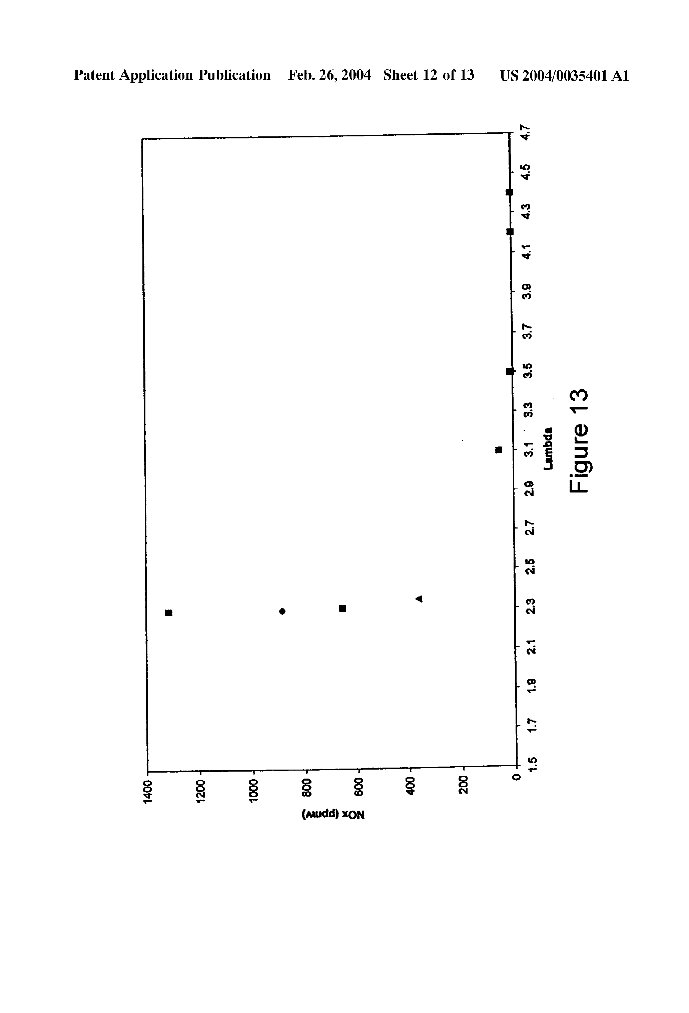
the hydrogen Storage unit prior to discharge to calculate a 0032 FIG. 13, shows NO emissions of the hydrogen value indicative of the actual amount of hydrogen present in powered internal combustion engine of the present invention the hydrogen Storage unit. The known amount of hydrogen running on industrial grade hydrogen with respect to the 2. contained inside the hydrogen Storage unit is calculated and value (actual air-fuel ratio divided by the stoichiometric updated using a value input into the microcontroller repre air-fuel ratio) at wide open throttle on a chassis dynamom Senting an amount of hydrogen input into the hydrogen eter.
Storage unit upon refueling.
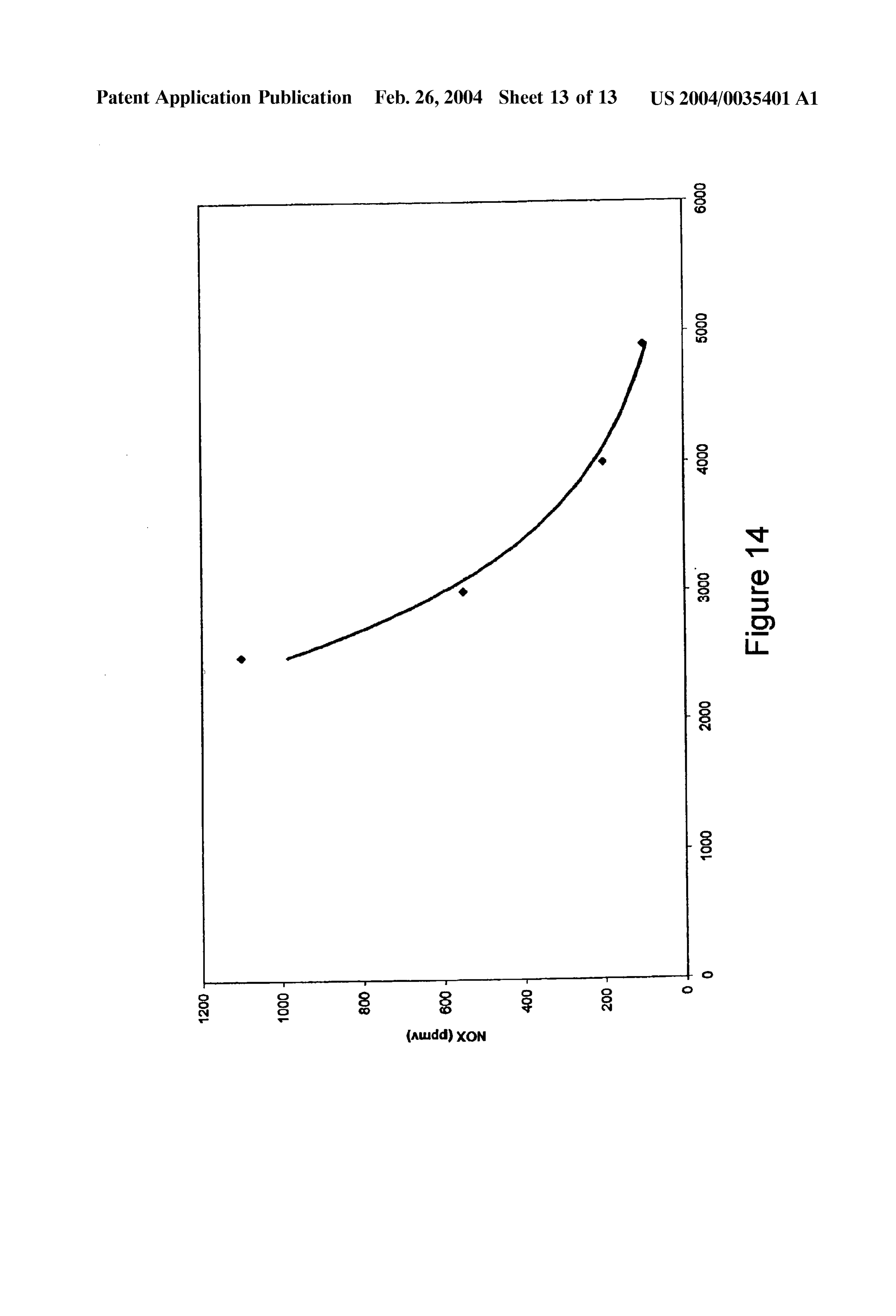
0033 FIG. 14, shows NO emissions of the hydrogen 0019. During operation of the fuel injector pulse width powered internal combustion engine of the present invention flow measurement System, the calculated hydrogen fuel running on ultra high pure hydrogen with respect to the 2. injector pulse width is directly input into an A/D input value (actual air-fuel ratio divided by the stoichiometric channel of the microcontroller. The microcontroller then air-fuel ratio) at wide open throttle on a water brake dyna calculates a volumetric flow rate of hydrogen consumed mometer.
over time based on the calculated hydrogen fuel injector pulse width and manifold absolute pressure. The volumetric 0034 FIG. 15, shows the NO emissions of the hydrogen flow of hydrogen consumed over time is decremented from powered internal combustion engine verSuS engine Speed for a known amount of hydrogen contained inside the hydrogen the present invention.
Storage unit prior to discharge to calculate a value indicative DETAILED DESCRIPTION OF THE of the actual amount of hydrogen present in the hydrogen INVENTION
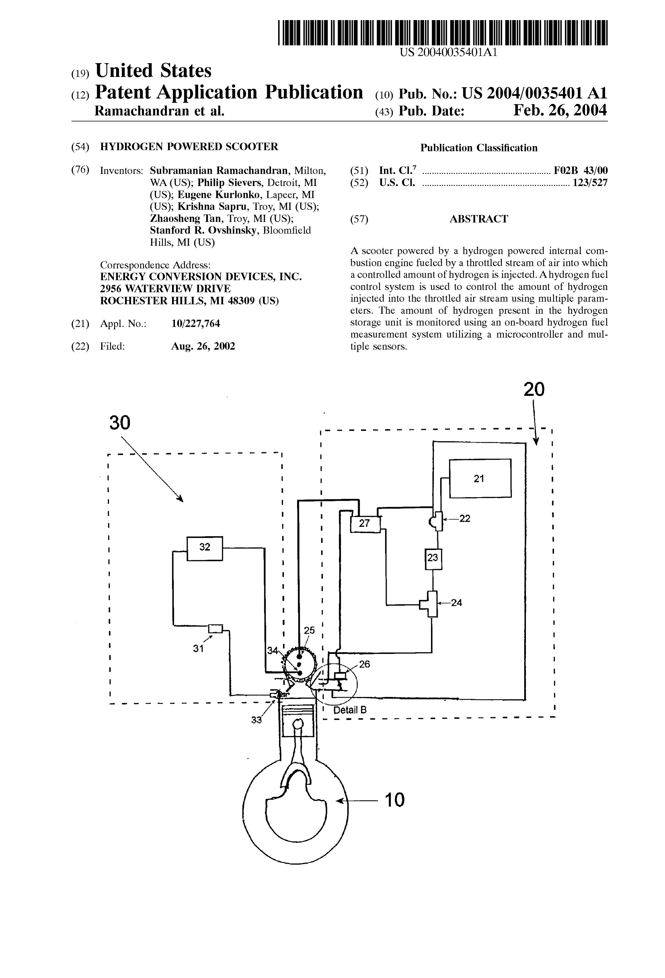
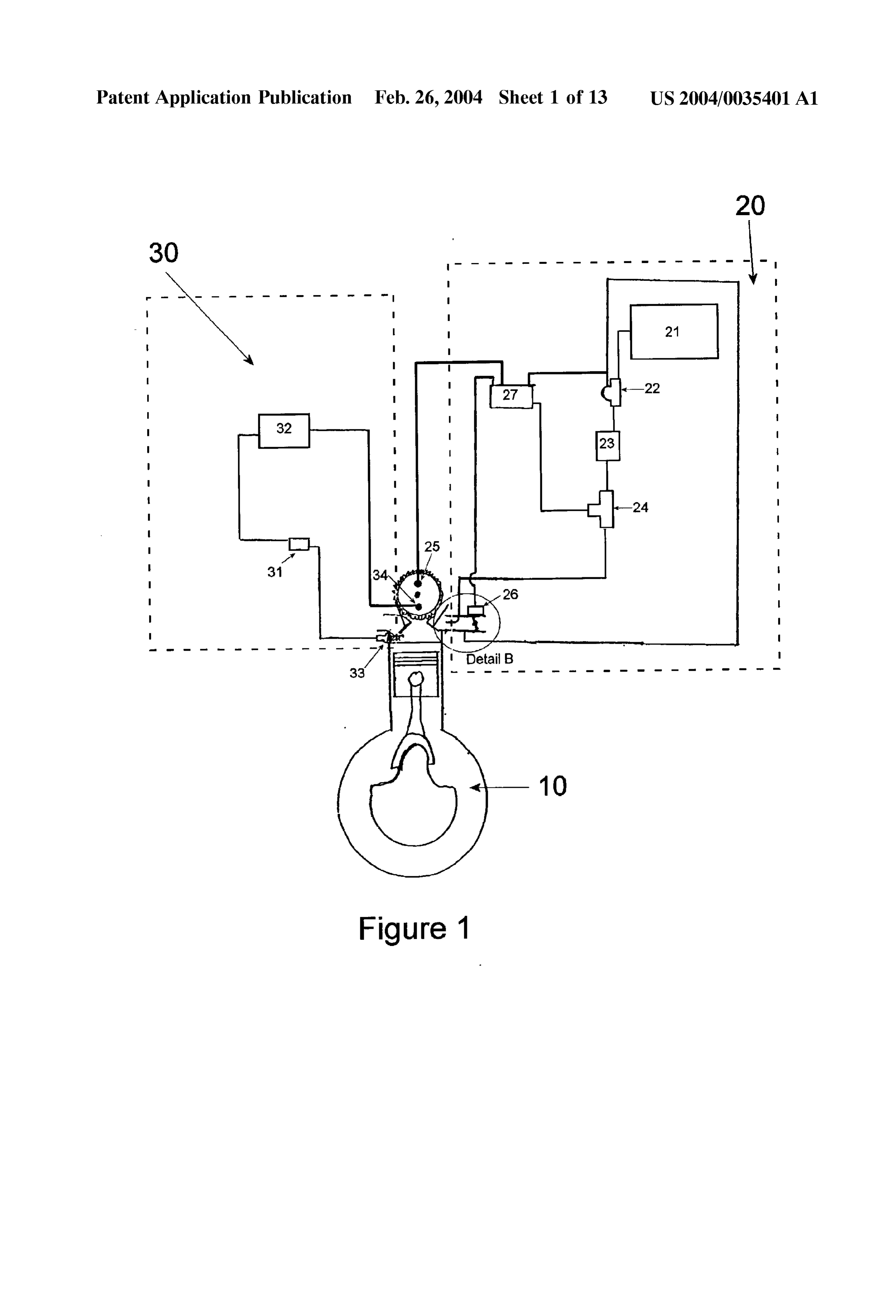
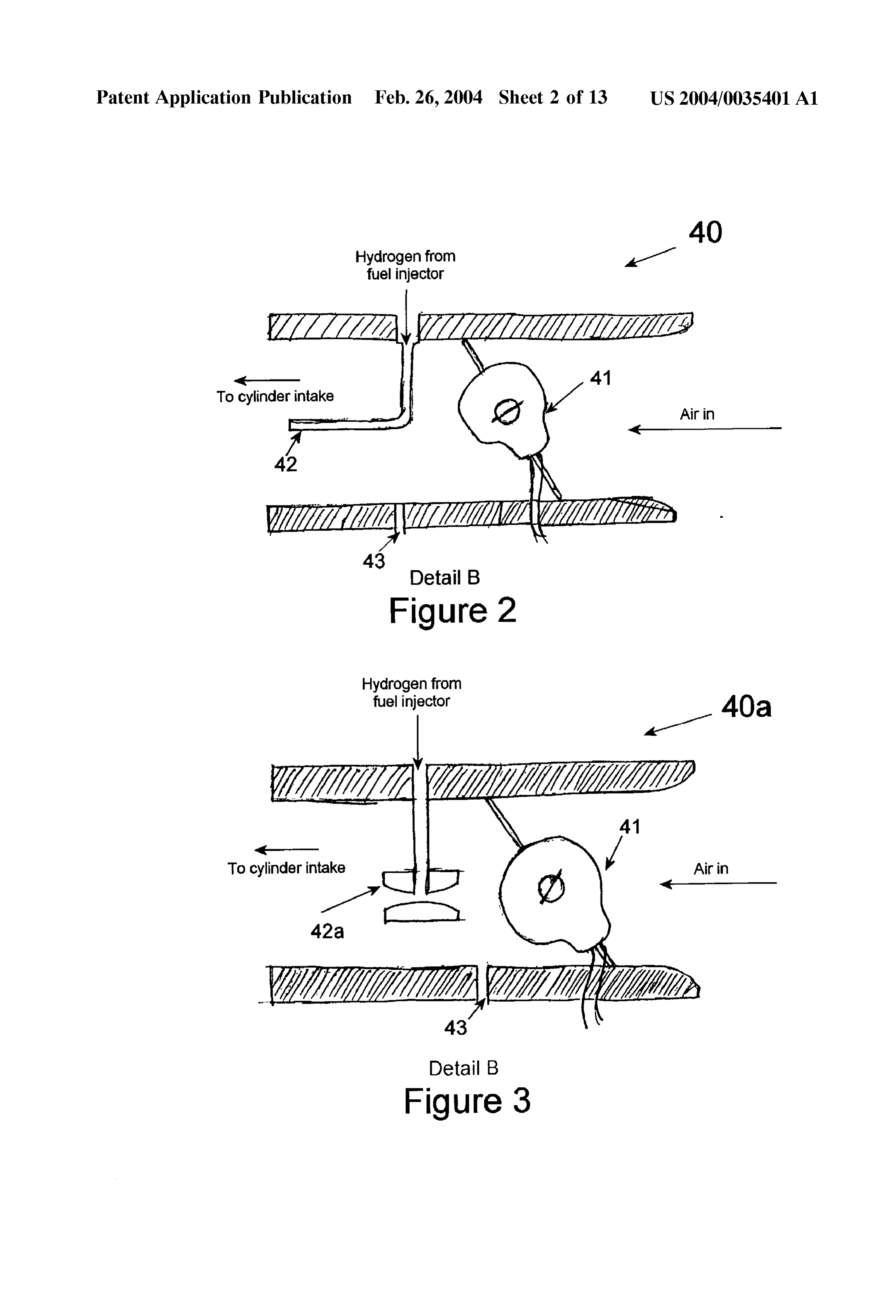
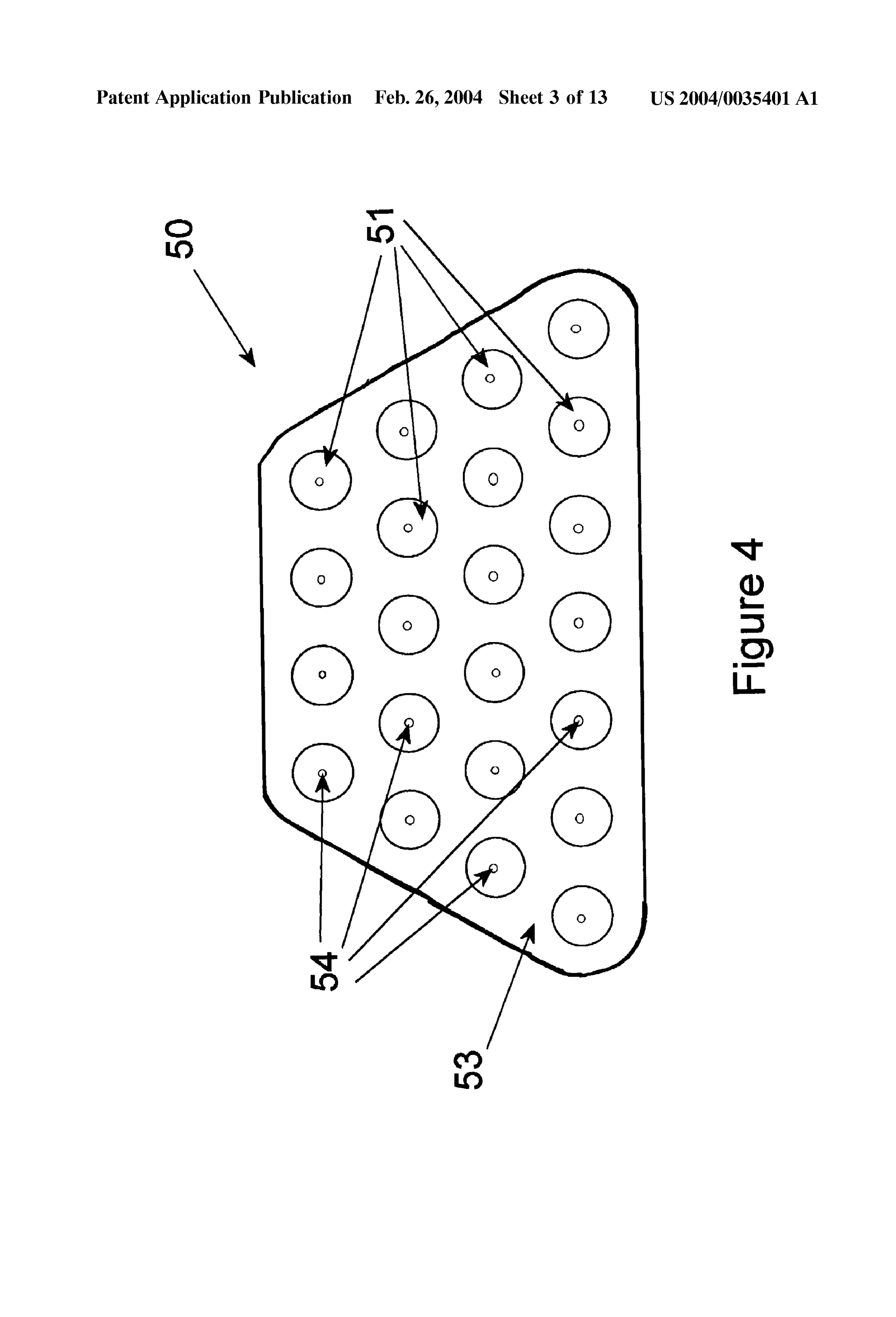
Storage unit. The known amount of hydrogen contained inside the hydrogen Storage unit is calculated and updated 0035. The present invention discloses a scooter propelled using a value input into the microcontroller representing an by a hydrogen powered internal combustion engine (ICE). amount of hydrogen input into the hydrogen Storage unit The hydrogen powered ICE utilizes a specially designed fuel upon refueling. induction System and ignition System to minimize NO BRIEF DESCRIPTION OF THE DRAWINGS emissions and efficiently power the Scooter. 0020 FIG. 1, shows a schematic representation of the 0036) The concept for the hydrogen powered internal present invention. combustion engine System of the present invention is exem 0021 FIG. 2, shows a depiction of the throttle body in plified in FIG. 1. The system includes a hydrogen powered accordance with the present invention utilizing a feed tube. internal combustion engine 10, a fuel induction System 20, and an ignition system 30. The fuel induction system 0022 FIG. 3, shows a depiction of the throttle body in includes a Source of gaseous hydrogen 21, a hydrogen fuel accordance with the present invention utilizing a boost preSSure regulator 22, a flash back arrestor 23, a hydrogen Venturi. fuel injector 24, a fuel injector trigger 25, a throttle position 0023 FIG. 4.shows a depiction of a tubular metal sensor 26, and a hydrogen fuel control system 27. The hydride Storage unit in accordance with the present inven ignition System 30 includes an ignition coil 31, a multiple tion. Spark discharge ignition controller 32, a Spark plug 33, a Spark trigger 34, and an optional manifold absolute preSSure 0024 FIG. 5, shows a cross-section of the hydrogen Sensor input.
Storage unit in accordance with the present invention.
0037. The hydrogen powered internal combustion engine 0.025 FIG. 6, shows a depiction of the hydrogen storage 10 may be a single cylinder 4 Stroke 80 cc engine, however, unit in accordance with the present invention the hydrogen powered internal combustion engine in accor 0.026 FIG. 7, shows a schematic representation of the dance with the present invention may also have multiple orifice plate based on-board fuel gauge in accordance with cylinders and vary accordingly. The hydrogen powered the present invention. internal combustion engine may be either air cooled or liquid cooled. During operation of the Scooter, a throttled 0027 FIG. 8, shows a flow chart for the orifice plate Stream of air is fed into the hydrogen powered internal based on-board fuel gauge in accordance with the present combustion engine. A controlled amount of hydrogen is invention. injected into the air Stream before the air Stream is Supplied 0028 FIG. 9, shows a schematic representation of the to the cylinders. To reduce backfire, the hydrogen is mixed fuel injector pulse width based on-board fuel gauge in with the air Stream as late as possible. After the hydrogen accordance with the present invention. mixes with the air Stream, the air/hydrogen mixture enters the cylinder through an intake Valve and is compressed and 0029 FIG. 10, shows a flow chart for the fuel injector combusted to provide work to a crankshaft. pulse width based on-board fuel gauge in accordance with the present invention. 0038. The throttle body 40 of the present invention is shown in FIG. 2. The throttle 41 allows a stream of air to 0030 FIG. 11, shows the brake horsepower of the engine flow toward the hydrogen powered internal combustion at wide open throttle versus RPM at a fixed value (actual engine 10. The hydrogen fuel injector 24 injects hydrogen air-fuel ratio divided by the stoichiometric air-fuel ratio) of into the air Stream via a hydrogen dispersing tube 42. The 3.5 for the present invention. end of the hydrogen dispersing tube through which the 0.031 FIG. 12, shows the brake horsepower of the engine hydrogen contacts the air Stream is positioned in the middle at wide open throttle versus RPM at a fixed value (actual of the air Stream to obtain optimal mixing between the air air-fuel ratio divided by the stoichiometric air-fuel ratio) of and the hydrogen. The manifold absolute pressure in the 2.3 for the present invention. throttle body may be measured by a sensor 43 placed after
Page 18
US 2004/0035401A1 Feb. 26, 2004
the throttle 41. In another embodiment, a boost venturi tube hydrogen Storage alloy 51. The hydrogen Storage alloy 42a may be used to disperse the hydrogen into the air Stream. preferably has a low plateau pressure to allow low preSSure This alternative embodiment is shown in FIG. 3. introduction of hydrogen into the hydrogen powered internal 0.039 The hydrogen powered internal combustion engine combustion engine. This insures that the alloy characteris is operated lean to minimize NO generation. The engine is tics are not a limiting factor. The hydrogen pressure inside the hydrogen Storage unit may be regulated down to 10-20 operating lean where 2 (Actual air-fuel ratio/Stoichiometric pSig. The hydrogen Storage unit is integrated into the Scooter air-fuel ratio) is greater than 1. Conversely, the engine is and is designed to derive its heat of endothermic desorption running rich where 2 is less than 1. The Stoichiometric from the engine exhaust, an engine coolant Stream, or other air-fuel ratio is approximately 34 kg air/kg. H2 for the Sources of heat. In Such cases, the exhaust gas or engine combustion of hydrogen. At this ratio there is neither a coolant Stream may pass through tubes in thermal contact Shortage nor an excess of air needed to completely combust with the hydrogen Storage alloy or the hydrogen Storage unit the hydrogen. may be heated by the exhaust gases or engine coolant Stream 0040. The hydrogen powered internal combustion engine in another manner. The interior of the hydrogen Storage unit described in the present invention will operate with a value may also be divided into compartments by thermally con between 0.13 and 10. Preferably operation will be with a 2. ductive materials to better accommodate heat transfer value between 1 and 3. Upon Startup and during hard throughout the vessel and prevent densification and Subse acceleration, the hydrogen engine may operate at a value quent expansion of the hydrogen Storage alloy (upon charg of 1 to provide maximum power. After Startup, the hydrogen ing with hydrogen) which can cause Strain to the wall of the engine may operate at a value greater than 2 to minimize unit. Such hydrogen Storage vessels are described in U.S. NO emissions. patent application Ser. No. 10/143,243, entitled “A Honey comb Hydrogen Storage Structure', filed on May 9, 2002 0041. The ignition for the hydrogen powered ICE may the disclosure of which is herein incorporated by reference. use a multiple Spark discharge controller. This type of Hydrogen may also be stored in gaseous or liquid form, ignition allows for a unique Set timing. The ignition is however, Storing hydrogen in this manner imposes greater triggered off the camshaft rather than the crankshaft to Safety risks and design constraints due to the extreme eliminate the waste Spark occurring during the exhaust conditions needed to Store the hydrogen at Such conditions. Stroke, which may cause backfiring. A programmable igni tion control System may be used to modify the Stock ignition 0045 Across-sectional view of the hydrogen storage unit timing. The Spark can be programmed to occur at a specific 50 in accordance with the present invention is depicted in crank angle at a given Speed. A Sensor is utilized on the FIG. 4. The hydrogen storage unit 50 includes one or more camshaft allowing the ignition to only fire on the compres Segmented metal hydride Storage units 51 at least partially Sion Stroke. filled with a hydrogen Storage alloy 52, a plurality of heat conductive fins 53, and at least one gas filtration/distribution 0042. The control system is responsive to signals based tube 54. A croSS-Sectional view of a metal hydride Storage on the engine Speed, the manifold absolute preSSure, and the unit in accordance with the present invention is depicted in throttle position. Based on these signals, the control System FIG. 5. Preferably the metal hydride storage units will have provides a control Signal with a calculated pulse width to the a cylindrical Structure, however, other designs may be used hydrogen fuel injector, thereby controlling the amount of in accordance with the present invention. Heat conductive hydrogen Supplied to the hydrogen powered internal com Segmental plates 55 are used to Segment the interior of the bustion engine. The control System utilizes multiple Sensors metal hydride Storage units. The heat conductive Segmental to measure these quantities. The control System may also be plates have a tight contact with the inner wall of the metal modified to use additional input Such as the throttled air hydride Storage units, where the heat eXchange between the Stream temperature and exhaust oxygen for better control metal hydride and the Surroundings takes place. over the fuel delivery to the hydrogen powered internal combustion engine. 0046) The metal hydride storage units 51 are inserted through a plurality of heat conductive fins 53. The heat 0043. In addition to the electronic control of the pulse conductive fins have a plurality of L-ledged holes through width to meter the hydrogen flow, the flow is also metered which the metal hydride storage units 51 are placed. The pneumatically by biasing the hydrogen fuel preSSure regu L-ledged holes are Slightly Smaller than the diameter of the lator with the manifold vacuum. A sensor 43 is used to metal hydride Storage units to provide a tight fitting heat measure the manifold absolute pressure in the throttle body transferring area between the metal hydride Storage unit 51 40. Using the manifold absolute pressure (MAP) to bias the and the heat conductive fin 53 upon insertion of the metal hydrogen fuel preSSure regulator controls the hydrogen hydride storage unit 51 into the heat conductive fin 53. preSSure at the hydrogen fuel injector. The applied hydrogen Multiple heat conductive fins will be fitted onto each metal preSSure must be modulated about the mechanically Set point hydride Storage unit to form a tightly pressed Structure. The using the manifold vacuum. When the throttle opens wider heat conductive fins provide for exceptional heat transfer and the MAP increases, the hydrogen preSSure increases at between the metal hydride Storage units and the Surround the hydrogen fuel injector. Conversely, when the throttle is IngS.
closed, the MAP drops and the hydrogen pressure at the hydrogen fuel injector is lowered. The hydrogen will be 0047. At least one gas filtration/distribution tube 54 is provided to the hydrogen powered internal combustion inserted longitudinally through each metal hydride Storage engine from a Source of gaseous hydrogen 21. unit 51. The gas filtration/distribution tube 54 preferable has a thin wall and Small diameter to optimize room for hydro 0044) The source of gaseous hydrogen 21 may be a gen storage. The gas filtration/distribution tube 54 allows hydrogen storage unit 50 at least partially filled with a hydrogen to enter and exit the metal hydride Storage unit 51.
Page 19
US 2004/0035401A1 Feb. 26, 2004
The gas filtration/distribution tube 54 is wrapped with that flows over a Specific time interval is then calculated. Stainless Steel wire cloth 56 to allow only hydrogen to pass, This amount of hydrogen is then decremented from the while keeping the hydrogen Storage alloy 51 from escaping known amount of hydrogen inside the hydrogen Storage tank into the gas filtration/distribution tube 54. The heat conduc prior to discharge. The known amount of hydrogen present tive Segmental plates 55 have one or more holes to accom in the hydrogen Storage unit is able to be calculated because modate the gas filtration/distribution tubes 54. The gas each time the hydrogen Storage tank is refilled, the amount filtration/distribution tubes 54 may have a filter to further of hydrogen input into the hydrogen Storage tank is input prevent metal hydride fines from escaping the metal hydride into the microcontroller using a push button control 67. A Storage units. The gas filtration/distribution tubes are inter value representing the Volume of hydrogen input into the connected via a manifold. The manifold distributes hydro hydrogen Storage unit is added to a value representing the gen to the metal hydride Storage units upon refueling and Volume of hydrogen left in the hydrogen Storage unit and a combines the hydrogen Streams from each metal hydride value representing the revised Volume is Stored in the Storage unit to provide one hydrogen Stream to the hydrogen memory (EEPROM). During the next trip, a value repre fuel injector during operation of the vehicle. Alternatively, Senting the revised quantity of hydrogen Stored in the the metal hydride Storage units may be coupled to a header hydrogen Storage unit is used as a “starting value” from which will also provide a single Stream to the hydrogen fuel which the instantaneous consumption is decremented. Using injector. the amount of hydrogen present in the hydrogen Storage tank and the amount of hydrogen exiting the tank, the microcon 0.048 Metal wool pads may be placed at the top and troller is able to calculate the amount of hydrogen present in bottom of each metal hydride Storage unit. The wool pads act the hydrogen Storage tank at any given time. The Volume of as an elastic Sponge to absorb the expansion and contraction hydrogen remaining in the hydrogen Storage unit is then of the metal hydride. The wool pads aid in reducing the continuously updated and the amount remaining is commu StreSS placed on the walls of the metal hydride Storage units. nicated to the operator using visual indicators 68. 0049. The resulting finned metal hydride storage units are 0052. In another embodiment, the instantaneous hydro closely bundled and encased in an externally framed box to gen flow is calculated using a fuel injector pulse width based form the hydrogen Storage unit. A base Support, connection flow measurement system 70. An example of this system is rods, and a top plate are utilized to form a Sturdy Structure shown in FIG. 8. A flow chart for the control unit in and frame the metal hydride storage unit bundle. The accordance with the present invention wherein a fuel injec material for the Supporting frame is preferable an aluminum tor pulse width based flow measurement System is used is alloy being lightweight and having excellent thermal con shown in FIG. 9. Using this system, the pulse width of the ductivity, however, other lightweight conductive materials hydrogen fuel injectorS 24, as calculated by the hydrogen may be Substituted. Hydrogen gas is distributed to or col fuel control system 27 is directly input into the A/D input lected from the individual metal hydride Storage units by a channel of the microcontroller 71. In addition, the micro manifold including multiple tubes or a header assembly. controller 71 uses the hydrogen pressure upstream and 0050. An on-board fuel gauge may be coupled to the downstream (MAP) of the hydrogen fuel injector as mea metal hydride hydrogen Storage unit. The on-board fuel sured by a MAP sensor 72. Knowing the equation of fuel gauge includes a hydrogen gas flow metering System, an flow through the hydrogen fuel injector 24, the volumetric on-board microcontroller configured to calculate the Volume hydrogen flow rate is calculated. Over a given interval, the of hydrogen used at an instant using the Signal input from the Volume of hydrogen that has been consumed is also calcu hydrogen gas flow metering System, a Visual indicator that lated. This value is decremented from the volume of hydro prompts the rider as to the amount of hydrogen present in the gen Stored on-board in the hydrogen Storage unit as calcu hydrogen Storage unit, and a System used to track the amount lated using the updated Volume as input into the of hydrogen present in the hydrogen Storage unit whenever microcontroller using a push button control 73 when the the amount of hydrogen within the hydrogen Storage unit is hydrogen Storage unit is refilled. The Volume of hydrogen refilled or depleted. remaining in the hydrogen Storage unit is then continuously updated and the amount remaining is communicated to the 0051) An orifice plate for an on-board fuel (hydrogen) operator using visual indicators 74. flow measurement System may be used as an on-board fuel 0053. The alloys used within the metal hydride hydrogen gauge for the hydrogen ICE Scooter. A diagram of the Storage unit may be any of those known in art for Such on-board fuel measurement System 60 utilizing an orifice purposes. Specific alloys include AB and ABs alloys, Such plate 61 is depicted in FIG. 6. A flow chart for the control as rare earth-nickel alloys, titanium-manganese alloys, tita unit in accordance with the present invention wherein an nium-zirconium alloys, titanium-iron alloys, magnesium orifice plate for an on-board fuel (hydrogen) measurement alloys, and the like. Examples of Such alloys can be found system is used is depicted in FIG. 7. The orifice plate is in U.S. Pat. Nos. 6,193,929; 6,103,024; 5,976,276; 5,916, positioned in the hydrogen Stream 62 between the hydrogen 381; 5,840,440; 4,832,913; 4,431,561 and in U.S. patent fuel pressure regulator and the hydrogen fuel injector. Pres application Ser. Nos. 09/573,240; 09/609,487; 09/902,320; Sure of the hydrogen Stream is measured after the hydrogen 09/901,816; 09/444,812; 09/873,863, all of which are herein fuel pressure regulator but before the orifice plate 61 using incorporated by reference.
a gas pressure Sensor 63. The change in pressure across the orifice plate is measured by a differential pressure transducer 0054) One example of a useful hydrogen storage alloy is 64 and the temperature of the hydrogen Stream is also a low temperature hydrogen Storage alloy which is non measured using a temperature Sensor 65. These parameters pyrophoric upon exposure to ambient atmosphere. The alloy are then input into a microcontroller 66 which calculates the particularly is non-pyrophoric even after hydrogen charge/ instantaneous hydrogen flow rate. The Volume of hydrogen discharge cycling. The alloy is an atomically engineered
Page 20
US 2004/0035401A1 Feb. 26, 2004
TiMn type alloy. Preferred embodiments of the non-pyro hydrogen powered internal combustion engine of the present phoric low temperature hydrogen Storage alloy comprises invention. The wide open throttle (WOT) data was collected titanium, Zirconium, Vanadium, chromium, and manganese. at 2500 RPM (0),3000 RPM(), 4000 RPM (A), and 4900 The alloy may further include iron and aluminum. Atomic RPM (X) over a lambda range of 2.1 to 4.0. The ignition engineering of the alloy includes adjusting the composition timing was fixed at 13 deg BTDC. Industrial grade hydrogen of the alloy to include increased chromium levels beyond was Supplied from a compressed gas Storage cylinder. that of conventional TiMn alloys. That is, as the chromium 0060 FIG. 13 shows exhaust NO versus lambda (A/F content of the alloy increases, the tendency to be pyrophoric versus Stoichiometric A/F) for the hydrogen powered inter decreases. Particularly preferred alloy compositions com nal combustion engine of the present invention. The WOT prise 0.5-10 at. 9% Zr, 29-35 at. 76 Ti, 10-15 at. 76 V, 13-20 data was collected at 2420 RPM (0), 3000 RPM (), and at. % Cr, 32-38 at. % Mn, 1.5-3.0 at. % Fe, and 0.05-0.5 at. 3860 RPM (A) over a lambda range of 2.3 to 4.3. The % Al. The alloy may further contain 1-10 at. % total of at ignition timing was fixed at 10 deg BTDC. Ultra High Pure least one element Selected from the group consisting of Ba, Hydrogen was Supplied from a compressed gas Storage Co, Cu, Cs, K, Li, Mm, Mo, Na, Nb, Ni, Rb, Ta, Tl, and W. cylinder.
Specific examples of useful alloys include the compositions
Zr, Tiss V12.54 Cris Mnso Fe2.2s Alo.21 and Zris Ti2.5 V12.54 0061 FIG. 14 shows the Exhaust NO versus engine Cris Mn36 Fe2.2s Alo.21. Speed for the hydrogen internal combustion engine of the 0.055 The effect of ignition timing, and lambda value present invention. The ignition timing is fixed at 13 deg (Air to fuel ratio) on the emissions (NO), engine horse BTDC and lambda is fixed at 2.3. Industrial grade hydrogen power and torque were Studied on the hydrogen powered was Supplied from a compressed gas Storage cylinder. AS internal combustion engine. The torque and horsepower engine speed decreases for a fixed lambda, the NOX in the measurements were both performed on an engine dynamom exhaust increases.
eter and chassis dynamometer. The engine temperature, 0062 Herein described is a steady state road test carried exhaust temperature, metal hydride Storage temperature, and out on the hydrogen ICE Scooter in accordance with the hydrogen preSSure were measured as well. The exhaust present invention. Hydrogen was Supplied from a metal emissions, NO, and hydrogen, were also measured and hydride Storage System in accordance with the present correlated to the air to fuel ratio. invention charged with 140 grams of hydrogen. The tests 0056. Using a chassis dynamometer test, one can deter were carried out at an outside temperature of 92 F. mine the steady State performance (range, fuel consumption, 0063 The hydrogen ICE scooter air to fuel ratio (lambda) horsepower and NO emissions) of a typical drive cycle that of 3.3-3.5 was maintained through out the run. The average includes acceleration, deceleration, and Start and Stop drive hydrogen consumption was 3.8 grams hydrogen/km. The patterns. average Speed during the road test was 32 kilometerS/hour 0057 FIG. 10 shows the brake horsepower of the hydro with a top speed of 40 kilometers/hour. The hydrogen ICE gen internal combustion engine at wide open throttle (WOT) Scooter obtained a range of 35 miles using 140 grams of versus RPM at a fixed air to fuel ratio of 3.5 for the present hydrogen.
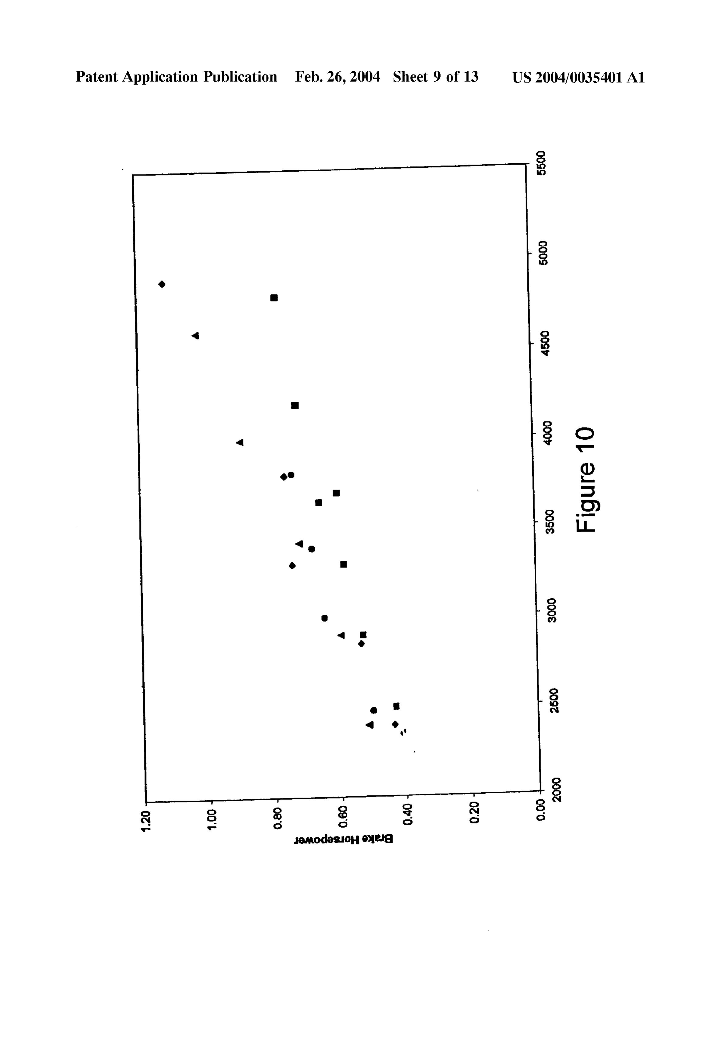
invention. The performance curves are shown for different 0064. The foregoing is provided for purposes of explain ignition timing, namely 10 deg. before top dead center ing and disclosing preferred embodiments of the present (BTDC) (O), 15 deg. BTDC (A), 20 deg. BTDC (0), and 25 invention. Modifications and adaptations to the described deg. BTDC (). Ultra High Pure Hydrogen was supplied embodiments, particularly involving changes to the fuel from a compressed gas Storage cylinder. Measurements were induction System, the hydrogen Storage unit, operating con carried out with a water brake absorber at the crankshaft.
The experimental results indicate Some of the power lost (at ditions of the hydrogen powered internal combustion 25 deg BTDC) can be recovered by retarding (15-20 deg engine, and the control System will be apparent to those BTDC) the ignition timing. This shows that the hydrogen is skilled in the art. These changes and others may be made Sensitive to Spark advance as compared to gasoline. without departing from the Scope or Spirit of the invention in the following claims.
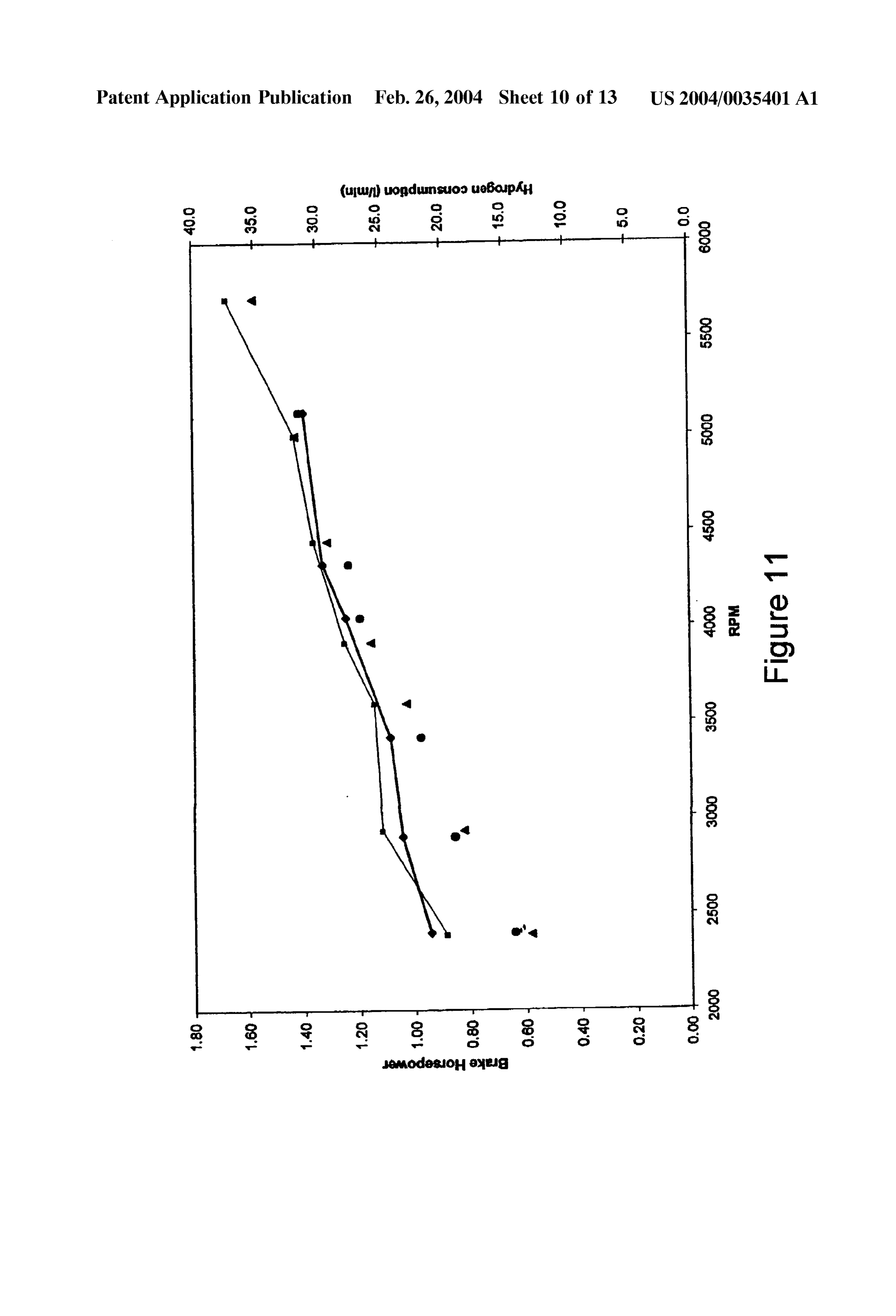
0.058 FIG. 11 shows the brake horsepower of the hydro gen internal combustion engine at wide open throttle (WOT) 1. A hydrogen powered Scooter comprising: versus RPM at a fixed air to fuel ratio of 2.3 for the present invention. The performance curves are shown for different a hydrogen powered internal combustion engine; ignition timings, namely 7 deg. BTDC (O) and 10 deg. a fuel induction System;
BTDC (A). Ultra High Pure Hydrogen was supplied from a compressed gas Storage cylinder. Measurements were car an ignition System;
ried out with a water brake absorber at the crankshaft. The hydrogen consumption (in liters/min) is also shown at an on-board hydrogen fuel gauge, and different ignition timings. The hydrogen consumption is a Source of gaseous hydrogen. shown at 7 deg. BTDC (0) and at 10 deg. BTDC (). The 2. The Scooter according to claim 1, wherein a throttled engine horsepower increases as the Spark is retarded (7 deg Stream of air is fed into Said hydrogen powered internal BTDC versus 10 deg BTDC) at a given engine speed, but is combustion engine.
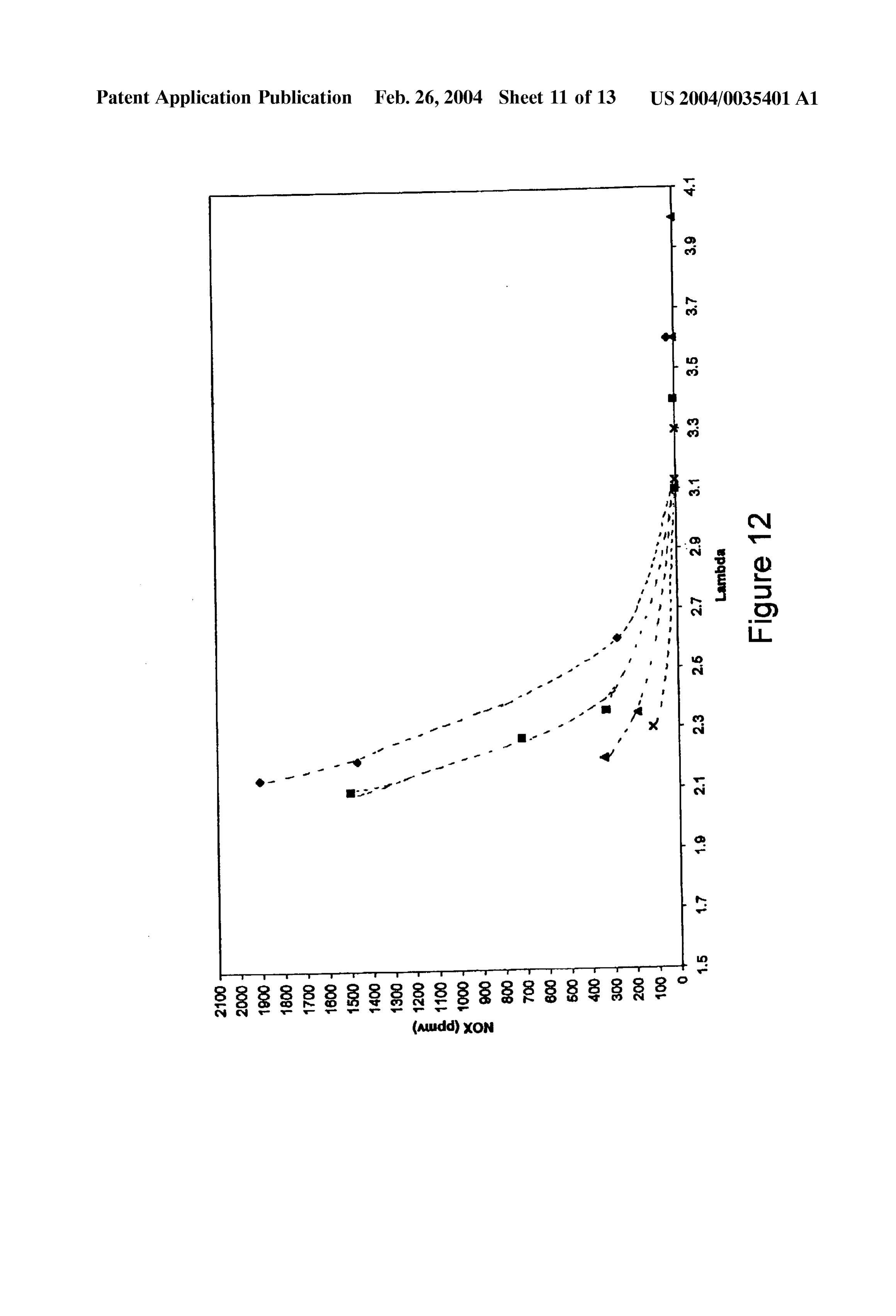
not very pronounced. Due to fast burning characteristics of 3. The hydrogen powered Scooter according to claim 2, hydrogen as compared to gasoline, a retarded Spark may be wherein Said hydrogen powered internal combustion engine preferred. comprises at least one cylinder. 0059 FIG. 12 shows exhaust NO versus lambda (actual 4. The hydrogen powered Scooter according to claim 3, air to fuel ratio versus stoichiometric air to fuel ratio) for the wherein Said fuel induction System comprises a hydrogen
Page 21
US 2004/0035401A1 Feb. 26, 2004
fuel control System, at least one hydrogen fuel injector, and 22. The hydrogen powered Scooter according to claim 21, a hydrogen fuel preSSure regulator. wherein Said on-board hydrogen Storage unit comprises at 5. The hydrogen powered Scooter according to claim 4, least one metal hydride Storage unit at least partially filled wherein Said hydrogen fuel control System is configured to with a hydrogen Storage alloy.
provide a hydrogen fuel control Signal having a calculated 23. The hydrogen powered Scooter according to claim 22, hydrogen fuel injector pulse width to Said hydrogen fuel wherein Said metal hydride Storage unit is in thermal contact injector. with a heat Source.
6. The hydrogen powered Scooter according to claim 5, 24. The hydrogen powered Scooter according to claim 23, wherein Said hydrogen fuel control Signal is based upon wherein Said heat Source is an exhaust Stream from Said engine Speed, manifold absolute pressure, and throttle posi hydrogen powered internal combustion engine. tion. 25. The hydrogen powered Scooter according to claim 23, 7. The hydrogen powered Scooter according to claim 5, wherein Said heat Source is an engine cooling Stream. wherein Said hydrogen fuel control Signal is based upon 26. The hydrogen powered Scooter according to claim 22, engine Speed, manifold absolute pressure, throttle position, wherein at least one gas filtration/distribution tube is temperature of Said throttled Stream of air, and amount of inserted longitudinally into Said metal hydride Storage unit. oxygen present in exhaust from Said hydrogen powered 27. The hydrogen powered Scooter according to claim 26, internal combustion engine. wherein Said hydrogen enters and exits Said metal hydride 8. The hydrogen powered Scooter according to claim 5, Storage unit via Said gas filtration/distribution tube. wherein Said hydrogen fuel control Signal causes Said hydro 28. The hydrogen powered Scooter according to claim 27, gen fuel injector to inject a calculated amount of hydrogen wherein Said gas filtration/distribution tube is wrapped with into said throttled stream of air. a stainless Steel wire cloth.
9. The hydrogen powered Scooter according to claim 8, 29. The hydrogen powered Scooter according to claim 22, wherein Said calculated amount of hydrogen is dispersed wherein Said metal hydride Storage unit is laterally divided into said throttled stream of air via a feed tube positioned into a plurality of compartments with at least one heat within said throttled stream of air. conductive Segmental plate.
10. The hydrogen powered Scooter according to claim 8, 30. The hydrogen powered Scooter according to claim 22, wherein Said calculated amount of hydrogen is dispersed wherein a metal wool pad is positioned at the top and bottom into Said throttled Stream of air via a boost venturi positioned of Said metal hydride Storage unit. within said throttled stream of air. 31. The hydrogen powered Scooter according to claim 22, 11. The hydrogen powered Scooter according to claim 8, wherein Said metal hydride Storage units are thermally wherein said throttled air stream has a value between 1 and connected via a plurality of heat conductive fins each having 10. a plurality of L-ledged holes.
12. The hydrogen powered Scooter according to claim 11, 32. The hydrogen powered Scooter according to claim 30, wherein Said throttled air Stream has a value between 2 and wherein Said metal hydride Storage units are inserted 5. through Said L-ledged holes.
13. The hydrogen powered Scooter according to claim 12, 33. The hydrogen powered Scooter according to claim 21, wherein said throttled air stream has a value between 3 and wherein Said on-board hydrogen Storage unit comprises an 4. on-board hydrogen fuel gauge.
14. The hydrogen powered Scooter according to claim 8, 34. The hydrogen powered Scooter according to claim 33, wherein Said throttled air Stream is compressed and com wherein Said on-board hydrogen fuel gauge comprises an busted in Said cylinders. on-board microcontroller, a Visual indicator showing the 15. The hydrogen powered Scooter according to claim 4, amount of hydrogen present in Said hydrogen Storage unit, wherein Said hydrogen fuel pressure regulator controls the and a System used to track the amount of hydrogen input into preSSure of Said hydrogen gas at Said hydrogen fuel injector. Said hydrogen Storage unit.
16. The hydrogen powered Scooter according to claim 3, 35. The hydrogen powered Scooter according to claim 34, wherein Said ignition System comprises a multiple Spark wherein Said on-board hydrogen fuel gauge further com discharge ignition controller, a Spark plug, and a Spark prises an orifice plate fuel measurement System. trigger. 36. The hydrogen powered Scooter according to claim 35, 17. The hydrogen powered Scooter according to claim 16, wherein Said orifice plate fuel measurement System com wherein Said multiple Spark discharge ignition controller is prises an orifice plate positioned between Said hydrogen fuel triggered off of a camshaft. preSSure regulator and Said hydrogen fuel injector and a 18. The hydrogen powered Scooter according to claim 17, plurality of Sensors.
wherein Said camshaft utilizes a Sensor allowing Said Spark 37. The hydrogen powered Scooter according to claim 36, plug to fire only on a compression Stroke. wherein Said plurality of Sensors measure a group of param 19. The hydrogen powered Scooter according to claim 16, eters comprising:
wherein Said ignition System further comprises a program (A)hydrogen gas pressure before said orifice plate, mable ignition control System. (B)hydrogen gas pressure drop across said orifice plate, 20. The hydrogen powered Scooter according to claim 19, and wherein Said programmable ignition control System causes
Said Spark plug to fire at a Specific crank angle at a given (C)temperature of Said hydrogen gas at Said orifice plate. Speed. 38. The hydrogen powered scooter according to claim 37, 21. The hydrogen powered Scooter according to claim 1, wherein Said on-board microcontroller calculates an instan wherein Said Source of gaseous hydrogen comprises an taneous flow rate of hydrogen gas using Said group of on-board hydrogen Storage unit. parameterS.
Page 22
US 2004/0035401A1 Feb. 26, 2004
39. The hydrogen powered scooter according to claim 38, 52. The hydrogen powered Scooter according to claim 46, wherein Said instantaneous flow rate of hydrogen gas is wherein a metal wool pad is positioned at the top and bottom decremented from a known amount of hydrogen contained of Said metal hydride Storage unit. inside Said hydrogen Storage unit prior to discharge to 53. The hydrogen powered Scooter according to claim 46, calculate a value indicative of the actual amount of hydrogen wherein Said plurality of heat conductive fins each have a present in Said hydrogen Storage unit. plurality of L-ledged holes.
40. The hydrogen powered scooter according to claim 39, 54. The hydrogen powered Scooter according to claim 53, wherein Said known amount of hydrogen contained inside
Said hydrogen Storage unit is calculated using a value input wherein Said metal hydride Storage units are inserted into Said microcontroller representing an amount of hydro through Said L-ledged holes.
gen input into Said hydrogen Storage unit upon refueling. 55. The hydrogen powered Scooter according to claim 46, 41. The hydrogen powered Scooter according to claim 34, wherein Said on-board hydrogen fuel gauge comprises an wherein Said hydrogen gas flow metering System further on-board microcontroller, a Visual indicator showing the comprises a fuel injector pulse width flow measurement amount of hydrogen present in Said hydrogen Storage unit, System. and a System used to track the amount of hydrogen input into 42. The hydrogen powered Scooter according to claim 41, Said hydrogen Storage unit.
wherein Said calculated hydrogen fuel injector pulse width is 56. The hydrogen powered scooter according to claim 55, directly input into an A/D input channel of Said microcon wherein Said on-board hydrogen fuel gauge further com troller. prises an orifice plate fuel measurement System. 43. The hydrogen powered Scooter according to claim 42, 57. The hydrogen powered scooter according to claim 56, wherein Said microcontroller calculates a volumetric flow rate of hydrogen consumed over time based on Said calcu wherein Said orifice plate fuel measurement System com lated hydrogen fuel injector pulse width and manifold abso prises an orifice plate positioned between Said hydrogen fuel lute pressure. preSSure regulator and Said hydrogen fuel injector and a 44. The hydrogen powered Scooter according to claim 43, plurality of Sensors.
wherein Said Volumetric flow rate of hydrogen consumed 58. The hydrogen powered scooter according to claim 57, over time is decremented from a known amount of hydrogen wherein Said plurality of Sensors measure a group of param contained inside Said hydrogen Storage unit prior to dis eters comprising:
charge to calculate a value indicative of the actual amount of (A)hydrogen gas pressure before said orifice plate, hydrogen present in Said hydrogen Storage unit.
45. The hydrogen powered Scooter according to claim 44, (B)hydrogen gas pressure drop across said orifice plate, wherein Said known amount of hydrogen contained inside and
Said hydrogen Storage unit is calculated using a value input into Said microcontroller representing an amount of hydro (C)temperature of Said hydrogen gas at Said orifice plate. gen input into Said hydrogen Storage unit upon refueling. 59. The hydrogen powered scooter according to claim 58, 46. A hydrogen Storage unit comprising: wherein Said on-board microcontroller calculates an instan taneous flow rate of hydrogen gas using Said group of a plurality of metal hydride Storage units at least partially parameterS.
filled with a hydrogen Storage alloy; 60. The hydrogen powered scooter according to claim 59, a plurality of heat conductive fins thermally coupled to wherein Said instantaneous flow rate of hydrogen gas is Said plurality of metal hydride Storage units, decremented from a known amount of hydrogen contained inside Said hydrogen Storage unit prior to discharge to at least one gas filtration/distribution tube longitudinally calculate a value indicative of the actual amount of hydrogen inserted into Said metal hydride Storage unit; present in Said hydrogen Storage unit. at least one heat conductive Segmental plate configured to 61. The hydrogen powered Scooter according to claim 60, divide Said metal hydride Storage unit into a plurality of wherein Said known amount of hydrogen contained inside compartments, and Said hydrogen Storage unit is calculated using a value input into Said on-board microcontroller representing an amount an on-board hydrogen fuel gauge. of hydrogen input into Said hydrogen Storage unit upon 47. The hydrogen powered Scooter according to claim 22, refueling.
wherein Said metal hydride Storage unit is in thermal contact 62. The hydrogen powered Scooter according to claim 55, with a heat Source. wherein Said hydrogen gas flow metering System further 48. The hydrogen powered Scooter according to claim 47, comprises a fuel injector pulse width flow measurement wherein Said heat Source is an exhaust Stream from Said System.
hydrogen powered internal combustion engine. 63. The hydrogen powered Scooter according to claim 62, 49. The hydrogen powered Scooter according to claim 47, wherein Said calculated hydrogen fuel injector pulse width is wherein Said heat Source is an engine cooling Stream. directly input into an A/D input channel of Said microcon 50. The hydrogen powered scooter according to claim 46, troller.
wherein Said hydrogen enters and exits Said metal hydride 64. The hydrogen powered Scooter according to claim 63, Storage unit via Said gas filtration/distribution tube. wherein Said microcontroller calculates a volumetric flow 51. The hydrogen powered Scooter according to claim 46, rate of hydrogen consumed over time based on Said calcu wherein Said gas filtration/distribution tube is wrapped with lated hydrogen fuel injector pulse width and manifold abso a stainless Steel wire cloth. lute pressure.
Page 23
US 2004/0035401A1 Feb. 26, 2004
65. The hydrogen powered Scooter according to claim 64, 66. The hydrogen powered Scooter according to claim 65, wherein Said Volumetric flow rate of hydrogen consumed wherein Said known amount of hydrogen contained inside over time is decremented from a known amount of hydrogen Said hydrogen Storage unit is calculated using a value input contained inside Said hydrogen Storage unit prior to dis into Said microcontroller representing an amount of hydro charge to calculate a value indicative of the actual amount of gen input into Said hydrogen Storage unit upon refueling. hydrogen present in Said hydrogen Storage unit. k k k k k

Provenance
- Collection
- Patents citing this work
- Original assignee
- Energy Conversion Devices Inc
- Pages
- 23
- Method
- pdftotext (the PDF's own text layer) + pdftoppm 300dpi page scans
- Patent office record
- patents.google.com →
- Source
- Google Patents citing-documents table
- Inventors
- Subramanian Ramachandran; Philip Sievers; Eugene Kurlonko; Krishna Sapru; Zhaosheng Tan; Stanford Ovshinsky; Energy Conversion Devices Inc
- Published
- 2004-02-26
- Transcribed from
- patentimages.storage.googleapis.com →