patent · US5572973
Method for cylinder identification in an internal combustion engine when idling
12 November 1996
Page 1 — bibliographic record
United States Patent (19) 11 Patent Number: 5,572,973 Schenk 45) Date of Patent: Nov. 12, 1996 (54) METHOD FOR CYLINDER 5,085,191 2/1992 Okuda ..................................... 123/414 IDENTIFICATION IN AN INTERNAL 5,099,810 3/1992 Borst ....................................... 123/414 COMBUSTION ENGINE WHEN IDLENG 5,099,811 3/1992 Frantz et al............................. 123/46 5,209.202 5/1993 Maurer et al. .......................... 23/414 75 Inventor: Klaus Schenk, Bietigheim-Bissingen, 5,213,079 5/1993 Umemoto et al. ...................... 123,414 Germany 5,239,962 8/1993 Fukui et al. ............................ 123,414 5,263,450 1 1/1993 Hashimoto et al. .................... 123,414 73) Assignee: Robert Bosch GmbH, Stuttgart, 5,269,274 12/1993 Flaetgen et al. ........................ 23/414 Germany 5,291,409 3/1994 Richardson et al. ... 364/431.07 5,333,586 8/1994 Fukui ...................................... 123/414 (21) Appl. No.: 397,105 FOREIGN PATENT DOCUMENTS (22) PCT Filed: Nov. 27, 1993 203 576 12/1986 European Pat. Off.. (86 PCT No.: PCT/DE93/01134 425.953 5/1991 European Pat. Off. .
S371 Date: Mar. 6, 1995 WO89/08778 9/1989 WIPO
S 102(e) Date: Mar. 6, 1995 Primary Examiner-Raymond A. Nelli 87). PCT Pub. No.: WO94/13951 Attorney, Agent, or Firm-Kenyon & Kenyon PCT Pub. Date: Jun. 23, 1994 57) ABSTRACT (30) Foreign Application Priority Data A method for identifying cylinders in the case of a missing Dec. 16, 1992 DEI Germany .......................... 42 42 419.4 or faulty phase signal during the idling operation of internal combustion engines in which, an ignition spark is produced (51 Int. Cl." ............................ F02PS/00 with every crankshaft in every cylinder, and the specified (52) U.S. Cl. .............................................................. 123/414 ignition-advance angle of the idling control for at least one (58) Field of Search ..................................... 123/414, 416, ignition of each cylinder is altered in every second crank 123/415, 417,418, 339.1, 339.11; 73/116, shaft rotation. The reaction to the change in the ignition 117.3, 119 A; 364/431.07 advance angle in the advance direction or toward a later firing point is subsequently evaluated by detecting irregular (56 References Cited running or by monitoring the air pilot control value and by undertaking an appropriate cylinder allocation.
4,558,591 12/1985 Francis et al.. 9 Claims, 4 Drawing Sheets
SIGNAL NW 5
ACQUIRE PARAMETER
FOR QUAS
STEADY STATE
OUTPUT SET WALUE
FOR AIR PLOT CONTROL
GNON ADVANCE {
Page 2
Drawing sheet — no readable text.
Page 3
SIGNAL NW 5
MEASURES
ACOURE PARAMETER
FOR QUAS
STEADY STATE
OUTPUT SET VALUE
FOR AIR PILOT CONTROL
IGNITION ADVANCE KC
CHANGE IGNITION 1
ADVANCE ANGLE
(CIN CORRECT IGNITION < N
Page 4
SIGNAL NW 5
MEASURES
ACQUIRE PARAMETER - 9
FOR OUAS
STEADY STATE
OUTPUT SE WALUES 10
FOR AR PLOT CONTROL
OF IGNITION ADVANCE <
CHANGE IGNITION 11
ADVANCE ANGLE
19 OF AIR PILOT CONTROL 22
WALUE 2
CHANGE OF IGNITION CHANGE OF IGNITION < <CN CHANGE-IN-CHARGE IN COMPRESSION STROKE STROKE
SHIFT GNITION SIGNAL CANCEL /23 BY 3600 SAFETY
MEASURES
CANCEL
SAFETY
MEASURES
Page 5
Drawing sheet — no readable text.
Page 6
METHOD FOR CYLNDER ignition-control signal 1 are depicted over the arc of crank IDENTIFICATION IN AN INTERNAL shaft rotation, the intention being to elucidate, in particular, COMBUSTION ENGINE WHEN DLING the range of 0° to 720° (thus, two crankshaft revolutions). As is generally known, the crankshaft of a four-stroke internal
FIELD OF THE INVENTION combustion engine turns twice around its own axis during one combustion cycle. Accordingly, the piston moves twice
The present invention relates to a method for identifying in the direction of its top dead center and, in fact, once cylinders in internal combustion engines. during the compression stroke and, the other time, during the exhaust stroke. To ensure proper combustion, it is important
BACKGROUND INFORMATION for the spark plug ignition to take place during the com 10 pression stroke and not during the exhaust stroke, since
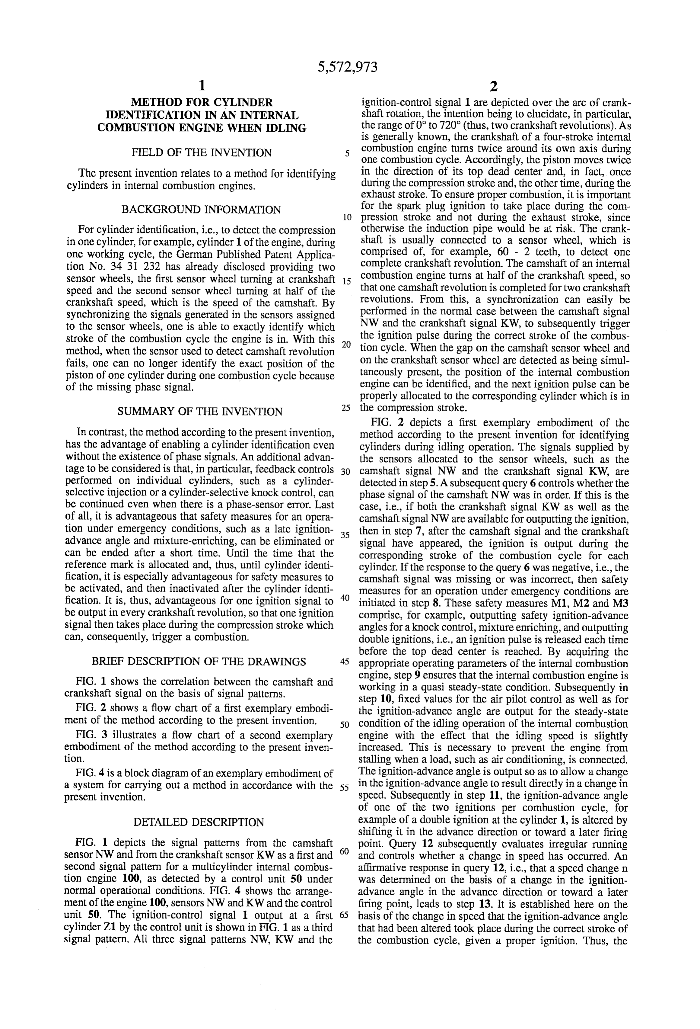
For cylinder identification, i.e., to detect the compression otherwise the induction pipe would be at risk. The crank in one cylinder, for example, cylinder 1 of the engine, during shaft is usually connected to a sensor wheel, which is one working cycle, the German Published Patent Applica comprised of, for example, 60 - 2 teeth, to detect one tion No. 34 31 232 has already disclosed providing two complete crankshaft revolution. The camshaft of an internal sensor wheels, the first sensor wheel turning at crankshaft 15 combustion engine turns at half of the crankshaft speed, so speed and the second sensor wheel turning at half of the that one camshaft revolution is completed for two crankshaft crankshaft speed, which is the speed of the camshaft. By revolutions. From this, a synchronization can easily be synchronizing the signals generated in the sensors assigned performed in the normal case between the camshaft signal to the sensor wheels, one is able to exactly identify which NW and the crankshaft signal KW, to subsequently trigger stroke of the combustion cycle the engine is in. With this 20 the ignition pulse during the correct stroke of the combus method, when the sensor used to detect camshaft revolution tion cycle. When the gap on the camshaft sensor wheel and fails, one can no longer identify the exact position of the on the crankshaft sensor wheel are detected as being simul piston of one cylinder during one combustion cycle because taneously present, the position of the internal combustion of the missing phase signal. engine can be identified, and the next ignition pulse can be properly allocated to the corresponding cylinder which is in
SUMMARY OF THE INVENTION the compression stroke.
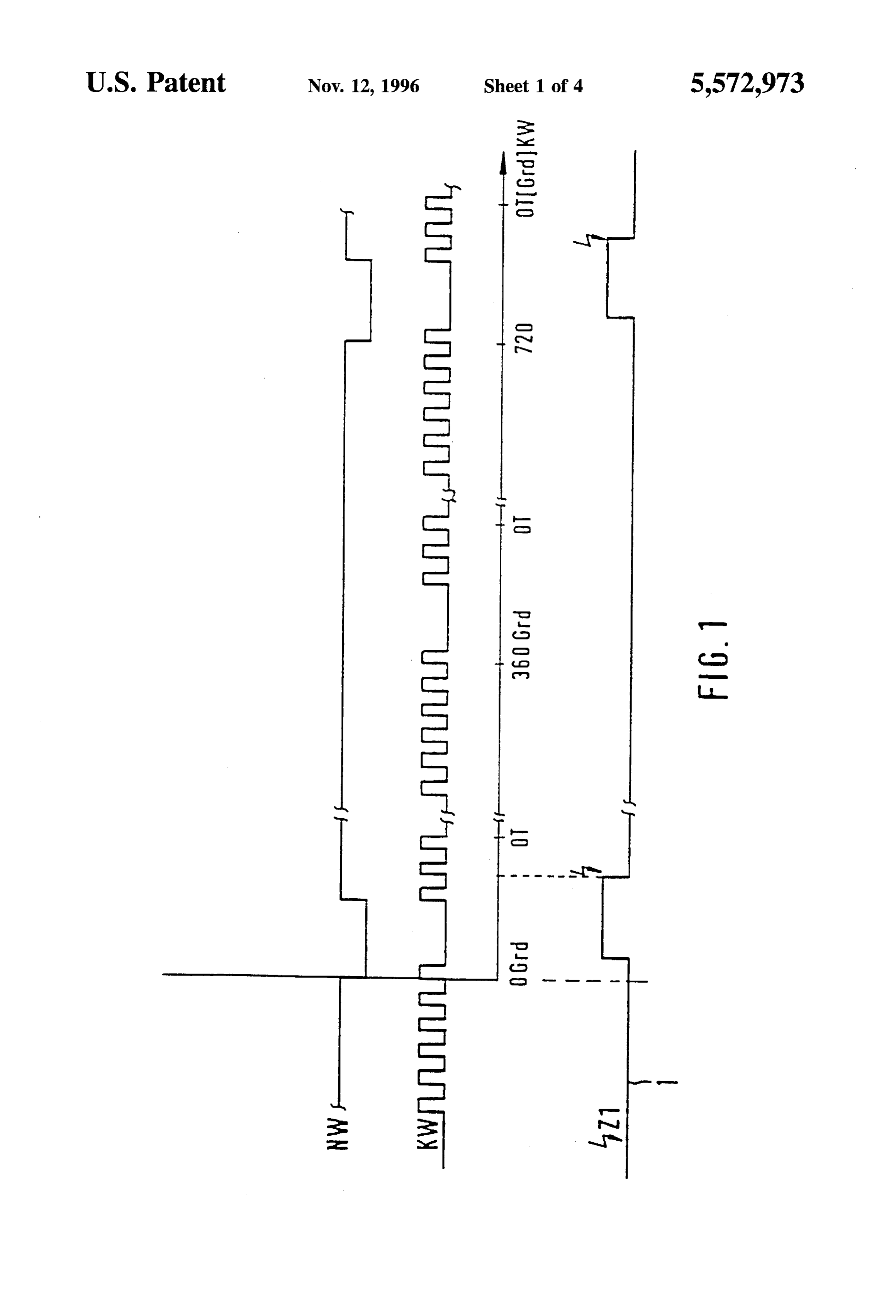
FIG. 2 depicts a first exemplary embodiment of the
In contrast, the method according to the present invention, method according to the present invention for identifying has the advantage of enabling a cylinder identification even cylinders during idling operation. The signals supplied by without the existence of phase signals. An additional advan the sensors allocated to the sensor wheels, such as the tage to be considered is that, in particular, feedback controls 30 camshaft signal NW and the crankshaft signal KW, are performed on individual cylinders, such as a cylinder detected in step 5. A subsequent query 6 controls whether the selective injection or a cylinder-selective knock control, can phase signal of the camshaft NW was in order. If this is the be continued even when there is a phase-sensor error. Last case, i.e., if both the crankshaft signal KW as well as the of all, it is advantageous that safety measures for an opera camshaft signal NW are available for outputting the ignition, tion under emergency conditions, such as a late ignition 35 then in step 7, after the camshaft signal and the crankshaft advance angle and mixture-enriching, can be eliminated or signal have appeared, the ignition is output during the can be ended after a short time. Until the time that the corresponding stroke of the combustion cycle for each reference mark is allocated and, thus, until cylinder identi cylinder. If the response to the query 6 was negative, i.e., the fication, it is especially advantageous for safety measures to camshaft signal was missing or was incorrect, then safety be activated, and then inactivated after the cylinder identi 40 measures for an operation under emergency conditions are fication. It is, thus, advantageous for one ignition signal to initiated in step 8. These safety measures M1, M2 and M3 be output in every crankshaft revolution, so that one ignition comprise, for example, outputting safety ignition-advance signal then takes place during the compression stroke which angles for a knock control, mixture enriching, and outputting can, consequently, trigger a combustion. double ignitions, i.e., an ignition pulse is released each time before the top dead center is reached. By acquiring the
BRIEF DESCRIPTION OF THE DRAWINGS 45 appropriate operating parameters of the internal combustion
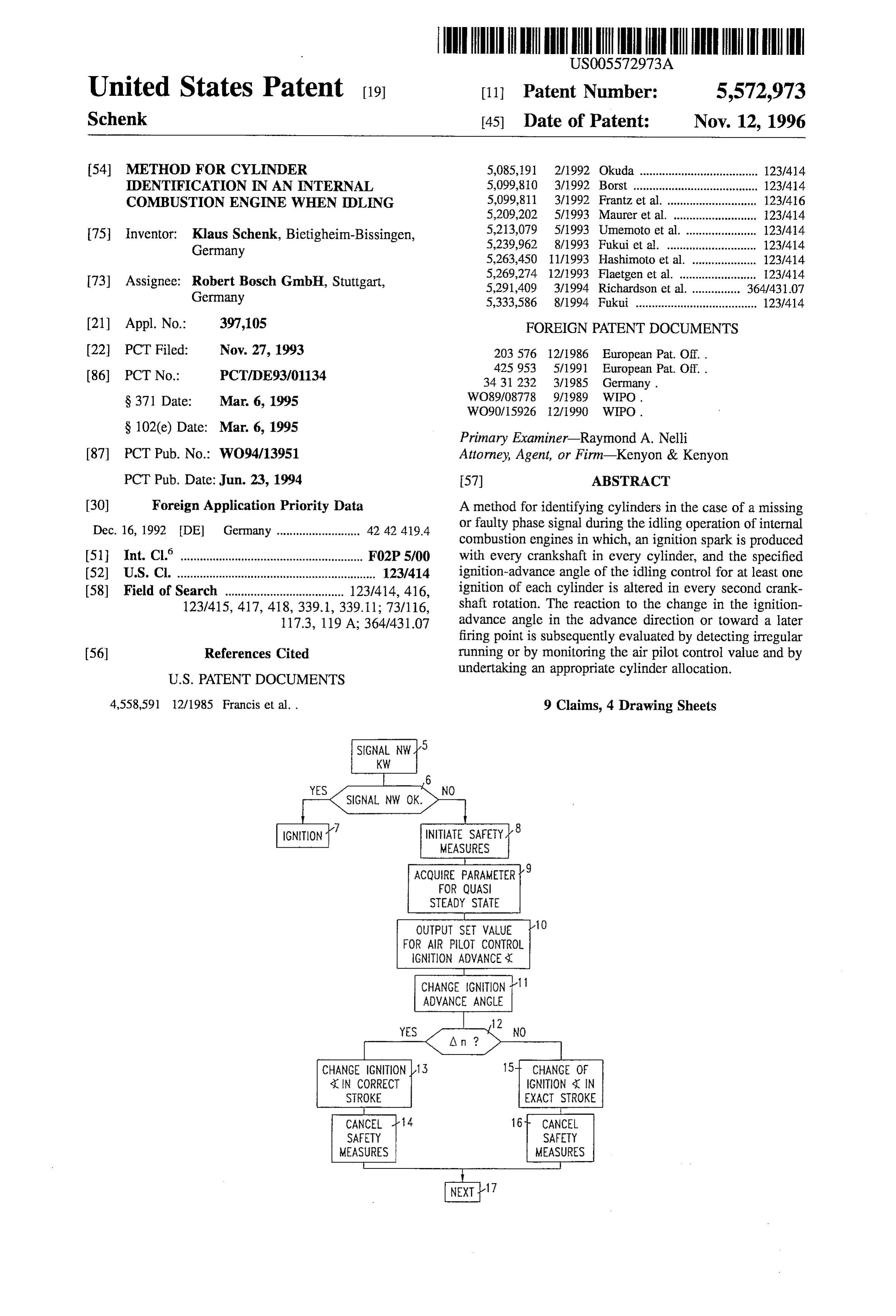
FIG. 1 shows the correlation between the camshaft and engine, step 9 ensures that the internal combustion engine is crankshaft signal on the basis of signal patterns. working in a quasi steady-state condition. Subsequently in step 10, fixed values for the air pilot control as well as for
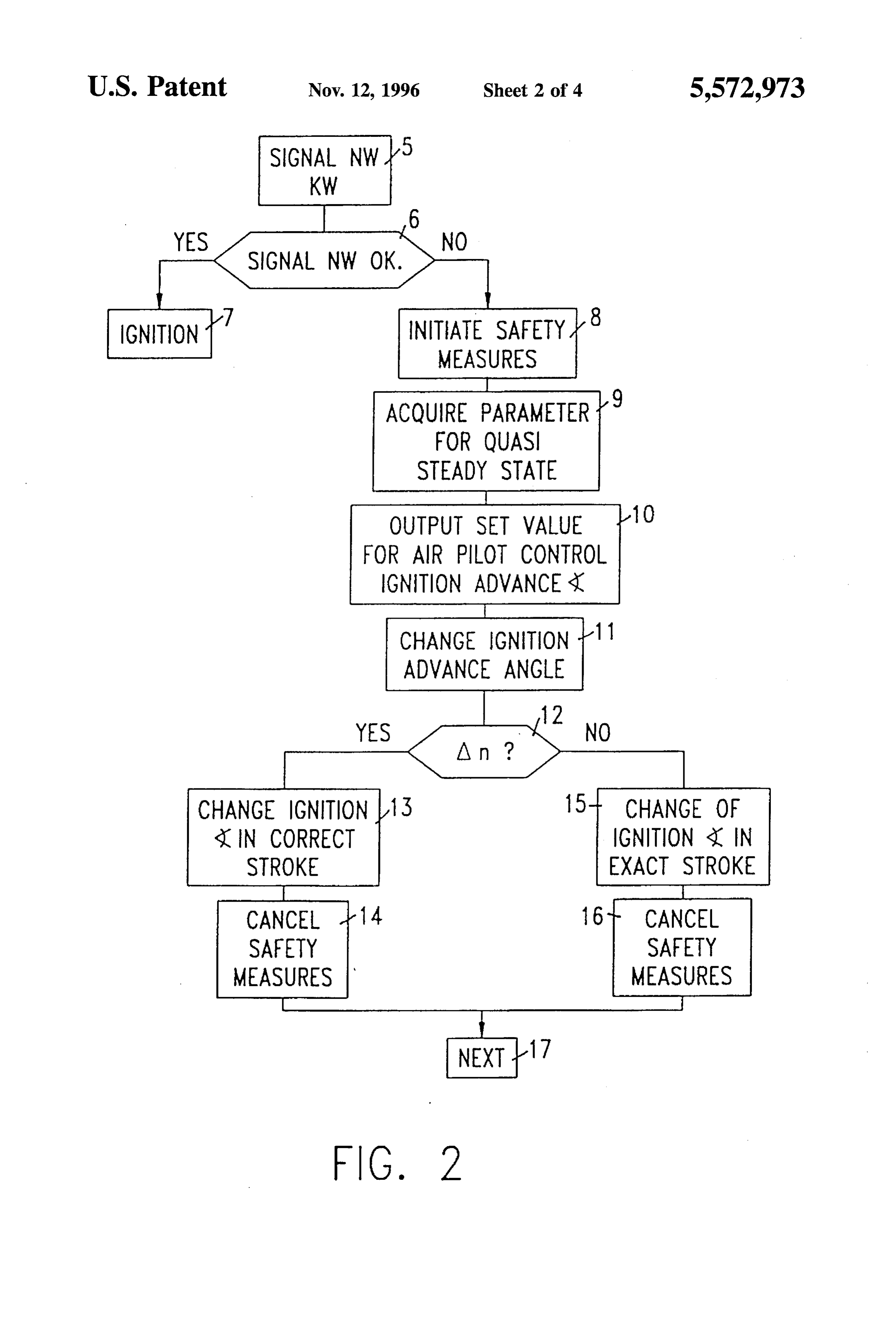
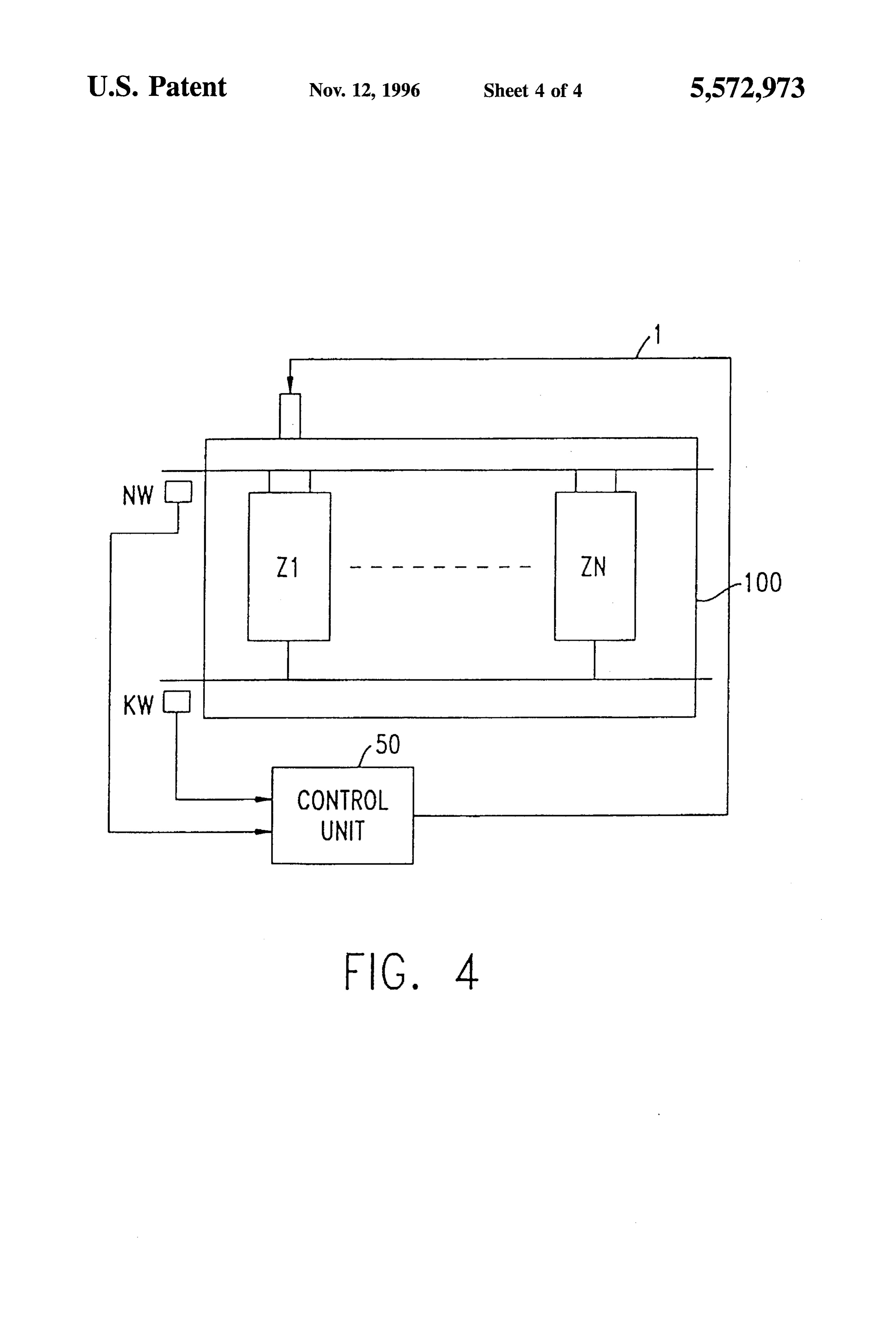
FIG. 2 shows a flow chart of a first exemplary embodi the ignition-advance angle are output for the steady-state ment of the method according to the present invention. 50 condition of the idling operation of the internal combustion FIG. 3 illustrates a flow chart of a second exemplary engine with the effect that the idling speed is slightly embodiment of the method according to the present inven increased. This is necessary to prevent the engine from tion. stalling when a load, such as air conditioning, is connected. FIG. 4 is a block diagram of an exemplary embodiment of The ignition-advance angle is output so as to allow a change a system for carrying out a method in accordance with the 55 in the ignition-advance angle to result directly in a change in present invention. speed. Subsequently in step 11, the ignition-advance angle of one of the two ignitions per combustion cycle, for
DETAILED DESCRIPTION example of a double ignition at the cylinder 1, is altered by shifting it in the advance direction or toward a later firing
FIG. 1 depicts the signal patterns from the camshaft 60 point. Query 12 subsequently evaluates irregular running sensor NW and from the crankshaft sensor KW as a first and and controls whether a change in speed has occurred. An second signal pattern for a multicylinder internal combus affirmative response in query 12, i.e., that a speed change in tion engine 100, as detected by a control unit 50 under was determined on the basis of a change in the ignition normal operational conditions. FIG. 4 shows the arrange advance angle in the advance direction or toward a later ment of the engine 100, sensors NW and KW and the control firing point, leads to step 13. It is established here on the unit 50. The ignition-control signal 1 output at a first 65 basis of the change in speed that the ignition-advance angle cylinder Z1 by the control unit is shown in FIG. 1 as a third that had been altered took place during the correct stroke of signal pattern. All three signal patterns NW, KW and the the combustion cycle, given a proper ignition. Thus, the
Page 7
ignition can be allocated to the cylinder 1, and the safety assigning an ignition having the altered ignition-advance measures introduced in step 8 for an operation under emer angle to a compression stroke of the at least one gency conditions, M1, M2 and M3, are again canceled. A cylinder;
negative response to query 12, i.e., no change in engine assigning the reference mark to a reference cylinder of the speed was able to be determined, leads in the work step 15 engine, and to the control unit recognizing that the output ignition took controlling the at least one cyclically repeating operation place with the change in the ignition-advance angle during of the engine in accordance with the assignment of the the change-in-charge stroke (exhaust stroke), so that the reference mark to the reference cylinder. change in the ignition-advance angle must have remained 2. The method according to claim I, wherein the quasi without consequence for the speed. 10 steady-state condition includes idling operation of the After the cylinder is synchronized, the next ignition is engine.
output by the control unit during the compression stroke, 3. The method according to claim 1, wherein the cycli having been displaced by 360° arc of crankshaft rotation. cally repeating operation includes at least one of ignition and The safety measures for an operation under emergency fuel injection processes.
conditions are canceled in a subsequent step 16. Steps 14 15 4. The method according to claim 1, wherein the ignition and 16 lead to step 17, which again controls whether the advance angle is altered by one of shifting the ignition phase signal was in order. When making the transition from advance angle in an advance direction and shifting the idling LL to part throttle running, the calculation is contin ignition-advance angle toward a later firing point in each ued with the corresponding gap as a cylinder allocation, additional crankshaft rotation.
otherwise no additional measures are carried out. 5. The method according to claim 1, further comprising 20 the steps of:
A second exemplary embodiment of cylinder allocation maintaining the quasi Steady-state condition of the engine shall be clarified in FIG.3 for the idle running operation of after the ignition-advance angle has been altered; and an internal combustion engine in the case of a missing or faulty phase signal. The initial part of this method is assigning the ignition having the altered ignition-advance identical to the method described in FIG. 2, so that steps 5 angle to an exhaust stroke of the at least one cylinder through 11 do not have to be explained again. After the 25 after the quasi steady-state condition is maintained. ignition-advance angle of each second ignition is changed 6. A method for identifying cylinders of an internal per crankshaft revolution in the work step 11, a work step 18 combustion engine in a quasi steady-state condition of the controls whether the change in the ignition-advance angle engine and for controlling at least one cyclically repeating has effected a reverse control of the airpilot control value for operation of the engine, comprising the steps of: the idling speed. If this is not the case, thus, the response to 30 detecting an arc of a rotation of a crankshaft using a the query 18 was negative, then in a subsequent step 19, the sensor operatively coupled to the crankshaft, and gen altered ignition is assigned to the change-in-charge stroke. erating a first signal based thereon; Thus, for the next ignition, the ignition signal is displaced by detecting a reference mark applied to the crankshaft using 360° toward the previously changed ignition in step 20. the Sensor, and generating a second signal based After allocation of the ignition to the corresponding stroke 35 thereon;
of the combustion cycle, the safety measures for an opera providing an ignition signal as a function of the first and tion under emergency conditions can be canceled in step 21. Second signals;
An affirmative response to the query 18, i.e., that the change establishing an air pilot control value for the quasi steady in the ignition-advance angle effected a change in the air State condition;
pilot-control value, leads to step 22, in which the ignition 40 altering an ignition-advance angle of at least one cylinder with the altered ignition-advance angle is recognized as an of the engine for a predetermined number of ignition ignition in the compression stroke. The output ignition was cycles;
thus in order. The safety measures M1, M2 and M3 can be canceled in step 23. Steps 21 and 23 of this method are monitoring the air pilot control value in order to detect a joined to step 24. change in the air pilot control value; The ignition or the injection are now triggered by the 45 assigning an ignition having the altered ignition-advance control unit using the ascertained cylinder allocation until angle to a compression stroke of the at least one the next control-unit reset. After that, the process begins cylinder and assigning the reference mark to a refer anew, whereby in step 24, the system jumps back to the ence cylinder of the engine when the change in the air beginning of the process. pilot control value is detected; and I claim: 50 controlling the at least one cyclically repeating operation 1. A method for identifying cylinders of an internal of the engine in accordance with the assignment of the combustion engine in a quasi steady-state condition of the reference mark to the reference cylinder. engine and for controlling at least one cyclically repeating 7. The method according to claim 6, wherein the ignition operation of the engine, comprising the steps of: advance angle is altered by one of shifting the ignition detecting an arc of a rotation of a crankshaft using a 55 advance angle in an advance direction and shifting the sensor associated with the crankshaft, and generating a ignition-advance angle toward a later firing point in each first signal based thereon; additional crankshaft rotation.
detecting a reference mark applied to the crankshaft using 8. The method according to claim 6, further comprising the Sensor, and generating a second signal based the step of:
thereon, 60 activating safety measures until the reference mark is processing the first and second signals; assigned to the reference cylinder. altering an ignition-advance angle of at least one cylinder 9. The method according to claim 8, wherein the safety measures are activated by providing the ignition signal in of the engine for a predetermined number of ignition each revolution of the crankshaft.
cycles;
detecting a change in a speed of rotation of the engine;
Provenance
- Collection
- Cited prior art
- Original PDF
- patentimages.storage.googleapis.com →
- Filed
- 1993-11-27
- Pages
- 7
- Method
- pdftotext (the PDF's own text layer) + pdftoppm 300dpi page scans
- Source
- Google Patents bibliographic record
- Granted
- 1996-11-12
- Inventors
- Klaus Schenk; Robert Bosch GmbH
- Transcribed from
- patentimages.storage.googleapis.com →