patent · US4408583
Ignition timing control
11 October 1983
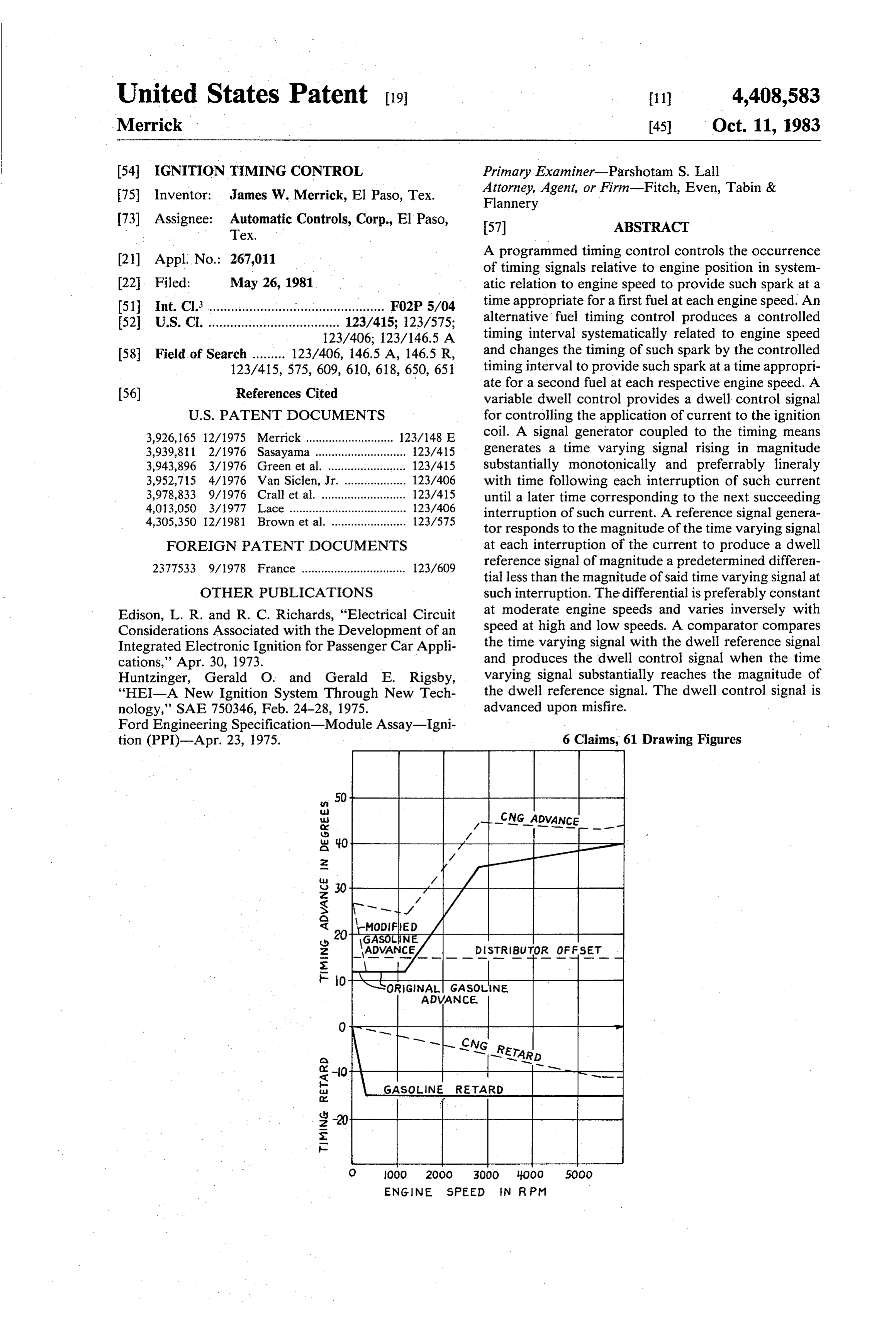
Page 1 — bibliographic record
United States Patent (19) 11 4,408,583 Merrick 45 Oct. 11, 1983 (54. IGNITION TIMING CONTROL Primary Examiner-Parshotam S. Lall 75 Inventor: James W. Merrick, El Paso, Tex. Attorney, Agent, or Firm-Fitch, Even, Tabin & Flannery 73 Assignee: Automatic Controls, Corp., El Paso, 57 ABSTRACT Tex.
21 Appl. No.: 267,011 A programmed timing control controls the occurrence of timing signals relative to engine position in system 22. Filed: May 26, 1981 atic relation to engine speed to provide such spark at a 51) Int. Cl. ................................................ FO2P 5/04 time appropriate for a first fuel at each engine speed. An 52 U.S. C. .................................... 123/415; 123/575; alternative fuel timing control produces a controlled 123/406; 123/146.5 A timing interval systematically related to engine speed (58) Field of Search ......... 123/406, 46.5 A, 146.5 R, and changes the timing of such spark by the controlled 123/415, 575, 609, 610, 618, 650, 651 timing interval to provide such spark at a time appropri ate for a second fuel at each respective engine speed. A 56) References Cited variable dwell control provides a dwell control signal
3,926, 165 12/1975 Merrick ........................... 123/148 E coil. A signal generator coupled to the timing means 3,939,811 2/1976 Sasayama ............................ 123/415 generates a time varying signal rising in magnitude 3,943,896 3/1976 Green et al. ...... ... 123A15 substantially monotonically and preferrably linerally 3,952,715 4/1976 Van Siclen, Jr. . ... 123A406 with time following each interruption of such current 3,978,833 9/1976 Crall et al. ... ... 123A15 until a later time corresponding to the next succeeding 4,013,050 3/1977 Lace .............. ... 123AO6 interruption of such current. A reference signal genera 4,305,350 12/1981 Brown et al. ....................... 123/575 torresponds to the magnitude of the time varying signal FOREIGN PATENT DOCUMENTS at each interruption of the current to produce a dwell 2377533 9/978 France ................................ 123/609 reference signal of magnitude a predetermined differen tial less than the magnitude of said time varying signal at
OTHER PUBLICATIONS such interruption. The differential is preferably constant Edison, L. R. and R. C. Richards, "Electrical Circuit at moderate engine speeds and varies inversely with Considerations Associated with the Development of an speed at high and low speeds. A comparator compares Integrated Electronic Ignition for Passenger Car Appli the time varying signal with the dwell reference signal cations,' Apr. 30, 1973. and produces the dwell control signal when the time Huntzinger, Gerald O. and Gerald E. Rigsby, varying signal substantially reaches the magnitude of "HEI-A New Ignition System Through New Tech the dwell reference signal. The dwell control signal is nology, SAE 750346, Feb. 24-28, 1975. advanced upon misfire.
Ford Engineering Specification-Module Assay-Igni tion (PPI)-Apr. 23, 1975. 6 Claims, 61 Drawing Figures
ENGINE SPEED IN RPM
Page 2
2O H1 GAS ONE ADVANCE
O O OOO 2OOO 3OOO 4000 SOOO
ENGINE SPEED IN RPM
28 2-9 46 12 BATTERY 12v NTON 12v A 4. 2O
CONTROL 32
SWITCH 2.
ASEAR
OUTPUT
SWITCH
CONDITIONING 3. Ja-EPER // H - - -- - -a a sur - m - - - - - U U U U U /
TIM NG
L wer was me -m as -- --- TMING - - --
Page 3
Drawing sheet — no readable text.
Page 4
Drawing sheet — no readable text.
Page 5
88O RPM
|| || POINTS
MAGNETO
s|| -90|| || || SIGNAL SGNAL
in VIII
O 5 O 5, 20 S O 5 2O TIME IN MILL SECONDS ME. N. MLL SECONds
ITNTH I
O 5 O 5 2O O 5 O 5 20
T ME IN MILL SECONDS TIME IN MLSECONDS
TTTTTP
O 5 O 15 20 O 5 O I5 20
N M L SECONDS TME N MILL SECONDS
Hill
HHH
O 5 O 15, 20 Cs 5 O s 2O
05 Hall
III III
TIME IN MILL SECONDS
fit
TM E N M L SECONDS
Page 6
600 RPMGASONE
300 RPM GASOLINE
still
LIT Li Li Li Li L.
(3) (4) (5) (O) () (2) (3) (4) (5) (6) (7) (8) (9) (IO) M. N. Mill seconds T ME N MS TIME N MILL SEco NDs
H2 TTTTTTTTTTT I
O 20 O 2O 3O 4o 5O ed 7O 8O 90 loo () (2) (5) (i) (2) ( ) (2) (3) (4) (5) (6) (7) (8) (9) (uo) TIME IN MEL SE CONDS TIME IN MS TME N M L L SECONDS
(3) (4) (5) C) C2) (O) () (2) (3) (4) (5) (6) (7) (8) (9) (Io) TIME IN MILL SECONDS ME in MS TIME N M L SECONds
30, 40 5O O O 2O 3O 40 50 60 7O 80 90 OO (O) () (2) (3) (4) (5) (o) () (2) (3) (4) (5) (6) (7) (8) (9) (IO) TME N. MSECONDS TME N MS TIME IN MLL SECONDs
Hugh H
(O) () (2) (3) (4) (5) (2) (o) () (2) (3) (4) (5) (e) (7) (a) (9) (IO) TIME N. MSECONDS TIME IN MS TME (N MIL SECONDS
TIME N 5 ECON ps
Page 7
2g. 12-I 2g. 13-I -2.g. 11-I 7O RPM 2J 88O RPM 3J 3500 RPM gy a . ||
N - 90- La Ss is a s' rigo
oH go o III.
alum
||20 | 40| | CO| | 80|| 00 5 O ||5 ||O | 5| | 20| | O | || 2|| ||
TIME IN MILL SECONDS TIME IN MILLISECONDS T ME IN MILL SECONDS
sa - 2 0. H
a. 3: PHL Ell
6s Fil---EF 3 O 20 40 6O 8O IOO O 5 O 5, 20 O 2. 3 4 5 TME IN MLSECOND5 TIME IN MILL SECONDS TME IN MLL SECONOS
12L. 13 d
c ALI ITT s ill|| || || Ely HH
ETH
i 4O II20 || to -4 0.
40 eo ao Í00 O 5 O 5 20 foLIT
TIME IN MILL SECONDs TIME IN MILL SECONDS TIME N M L SECONDS
u 5
s s g
uns 2 2
5u 3.s 5v -
TME N M L SECONDS
O 20 4-O 60 8O OO O 5 O
FME IN M L SECONDS TIME M M ILLISECONDS T ME N MILL SECONOS
Page 8
8OO RPM
35OO RPM
6 | | | | | | | | | 26 ...- 6
4 9> || 1 || | | | | SS 4.5
O 20 40 6O 80 f00 s O 5 20 G) 2. 3 4. T ME IN MLSECONDS TME N MLL SECONDS TIME IN MILL SECONDS
12P 3P 44 P
>0.4 | | | | | | | |
O 20 4O 60 8OO OO O O s 2O O 2 3. 4. s T ME IN MLL SECONDs TME M M L L SECONDS TIME N M L SECONDS
12 Q 13 Q 14Q
2 T -2 Z
-4 3. 5 - O ||A | 2.| | 3| | 4.| | 5 O 20 40 60 30 00 O 5 O 5 2O
TME IN MISECONDS TIME IN MIL SECONDS TIME IN M L SECONDS
2 || || || 2 || || ||
II, IIT III
TME IN MILLSECONDS TME IN MILL SECON pS TIME IN MILL SECONDS 12S 3S Al S
6/ F4FFFF
HITTMTT
DIII
TMS N MLL SECONDS T ME N MILL SECONDS TIME IN MILL SECONDS
Page 9
that, for example, there is a substantial difference be
IGNITION TIMING CONTROL tween the optimum timing advance for gasoline and that for LPG at idle, whereas at high speed the opti
This invention relates generally to automotive igni mum timing advance is about the same for both fuels. tion systems and more particularly to ignition systems This means that if the conventional distributor is ad for sparkignited internal combustion engines. Still more justed mechanically for proper advance at idle for LPG particularly it relates to timing controls for providing fuel, the programmed centrifugal timing control associ appropriate ignition timing for multiple fuels. It also ated with the distributor will cause the timing advance relates more particularly to such ignition systems in to be too great for LPG fuel at high speed. On the other cluding a variable dwell control. w 10 hand, if a compromise is used and the advance adjusted In spark discharge ignition systems, ignition timing to be proper at intermediate speeds, then the timing signals indicate when sparks are to be initiated in the advance for LPG fuel is inappropriate at both idle and spark gaps of respective spark plugs in the respective high speed. . cylinders of an internal combustion engine to cause In accordance with one aspect of the present inven combustion to be initiated in the respective cylinders. 15 tion a controlled timing interval is added to the conven Conventionally a spark is initiated in a respective cylin tional timing advance to provide a programmed timing der at a particular programmed point in the engine advance that is appropriate for a particular fuel at all cycle in advance of top dead center of the power stroke engine speeds. In accordance with the preferred em for the respective cylinder. In gasoline engines this is bodiment of the present invention a controlled timing typically about 10 in advance oftop dead center at idle. 20 interval is developed that varies linearly from one value However, at higher engine speeds it is desirable that the at idle to another value at high speeds. By the simple spark be advanced in a programmed manner as a func closure of a switch by the operator, this controlled tion of engine speed in order to provide appropriate timing interval is added to the conventional timing burning as the stroke reaches top dead center. Inasmuch advance interval present in the typical ignition system as the piston reaches top dead center more quickly at 25 for gasoline engines so that the timing becomes appro higher speeds, it is necessary to advance the time of priate for the alternative fuel. More particularly, in ignition in each cycle in order that the burning be prop accordance with the preferred embodiment of the in erly developed at the time of top dead center. This vention, the distributor is adjusted mechanically to ad requires the advance of the spark at higher engine vance the spark a fixed amount and then the timing speeds, programmed to provide an advance systemati 30 control circuit operates to retard the spark from that cally related to engine speed. This is provided by cen advance. When gasoline is used as a fuel, the gasoline is trifugal means associated with the conventional distrib retarded by just the amount of mechanical advance put utor of the engine, the distributor comprising a rotating in. However, when the alternative fuel is used, the pro switch that supplies the spark energy to the appropriate grammed controlled timing interval reduces the amount respective spark plugs. The centrifugal means causes 35 of advance less at low speed than at high speeds, leaving relative displacement between the engine and the rotat the spark advanced at lower speeds relative to the nor ing switch of the distributor, the relative displacement mal timing for gasoline ignition. being a function of engine speed. Typically, a timing of In accordance with another aspect of the present about 30" in advance of top dead center is desirable at invention a variable dwell control controls the timing of high engine speeds in modern gasoline engines. The 40 the application of current to the ignition coil prior to the centrifugal means advances the spark gradually from initiation of a spark by interruption of such current. A 10 as the engine speed increases from idle. signal generator responds to the output of the pro With the recent rise in the price and availability of grammed timing advance circuit to generate a time gasoline, alternative fuels are now being utilized. For varying signal rising in magnitude substantially mono example, liquified petroleum gas (LPG) and com 45 tonically and preferably linearly with time following pressed natural gas (CNG) are becoming common for each interruption of the current in the primary of the automative" use. These require special fuel tanks and ignition coil until a later time corresponding to the next special carburetors; however, such fuels are otherwise succeeding interruption. A reference signal generator adequate for operating conventional gasoline engines. responds to the magnitude of the time varying signal at A problem with using such fuels is that the timing of the 50 each interruption of the current to produce a dwell engine for gasoline operation is not optimum for opera reference signal. In a preferred embodiment of the in tion with these alternative fuels. More particularly, with vention, a peak signal is developed that corresponds to engines of the sort described above having a timing the magnitude of the time varying signal at the time of curve suitable for use with gasoline, timing for LPG current interruption. The dwell reference signal is a fuel should typically be about 21 advanced (relative to 55 voltage differential less than the peak voltage, such top dead center) at idle and 35' advanced at high speed differential being preferably substantially constant at (3000 RPM). With CNG fuel the timing curve might moderate operating engine speeds and otherwise in reasonably go from 25 at idle to 44' advanced at high versely related to engine speed. The time varying signal speed (3000 RPM). is compared to the dwell reference signal. When the It has been common to modify gasoline engines for time varying signal next substantially reaches the mag operating with LPG or CNG fuel. As suggested above, nitude of the dwell reference signal, the current through this has involved the replacement of the gasoline carbu the ignition coil is reinstituted. Thus, one of the princi retor with a carburetor appropriate for burning the pal aspects of the present invention is to provide a alternative fuels. At times the one has merely been pig method and apparatus for adjusting the timing of an gybacked upon the other. An effort has been made to 65 engine set for operation with one fuel, to produce igni accommodate the difference in timing by mechanical tion sparks at times appropriate for an alternative fuel at adjustment of the distributor, i.e., by adjusting the ad all engine speeds. Another principal aspect of the pres "vance by a fixed amount. The trouble with this has been ent invention is to provide a variable dwell control for
Page 10
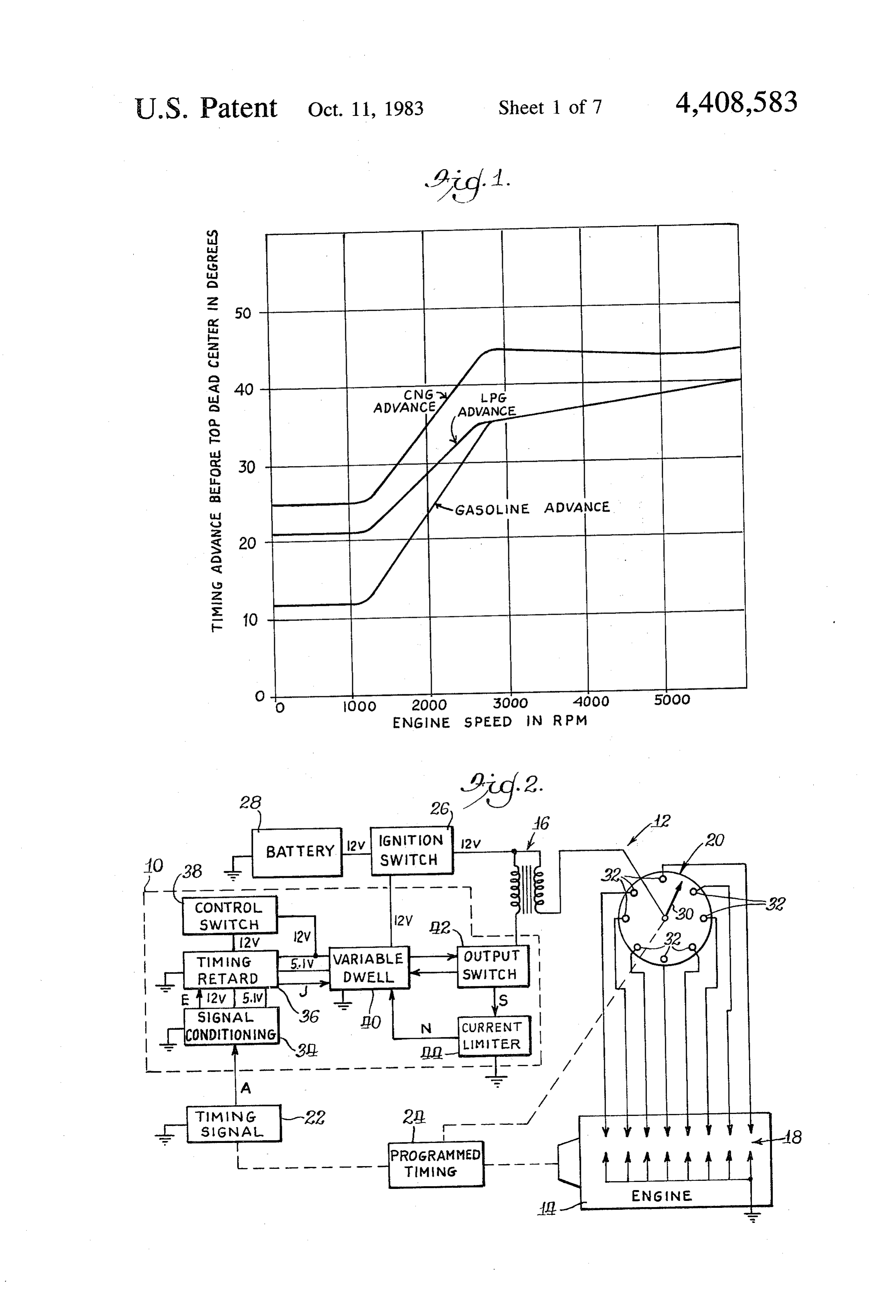
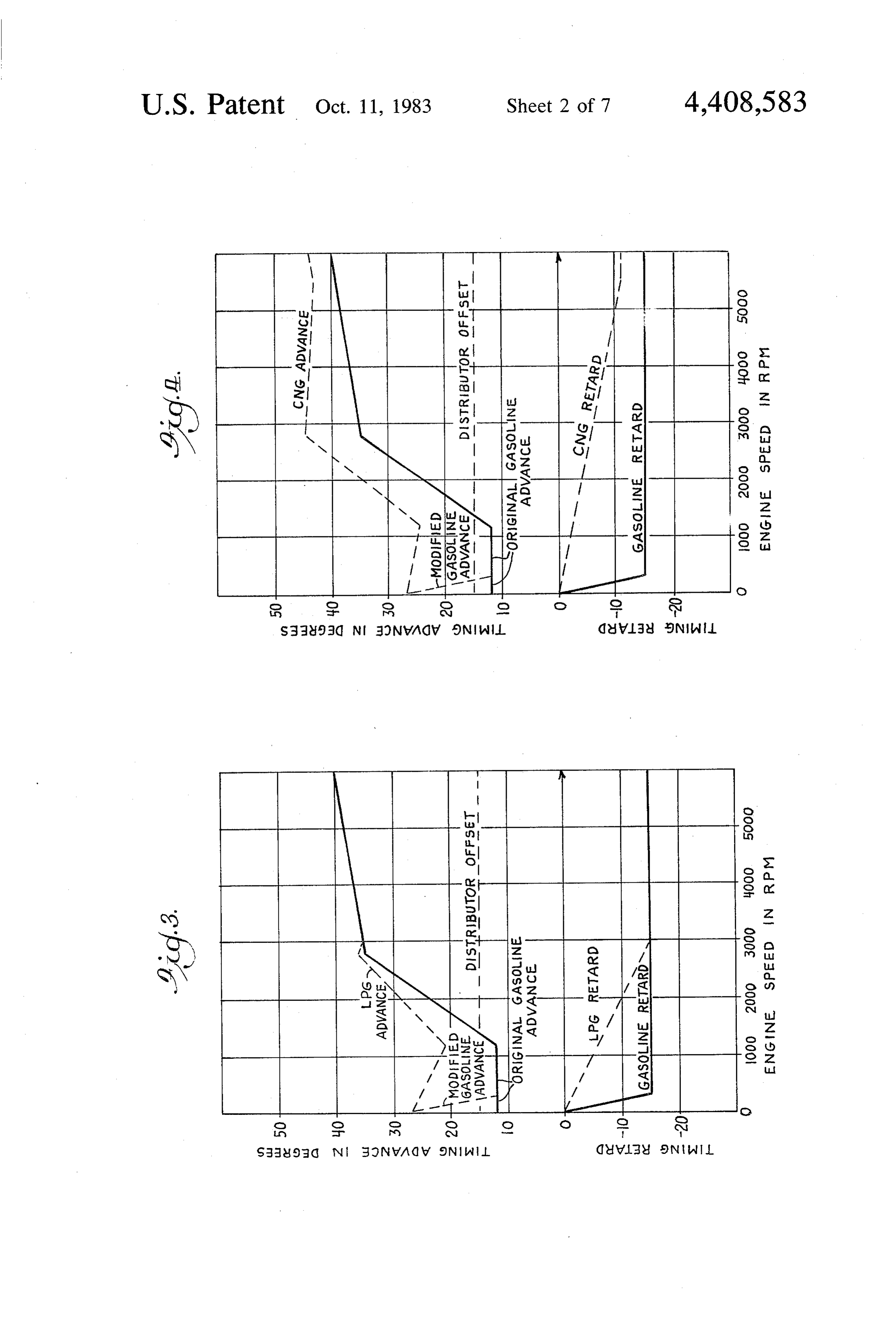
applying curent to the ignition coil at an appropriate tion for providing such programmed timing advance for time before current interruption. alternative fuels is illustrated generally in FIG. 2. These and other, aspects of the present invention will As shown generally in FIG. 2, the present invention become apparent from consideration of the following comprises an ignition timing control 10 as used in an detailed description, particularly when taken in con- 5 ignition system 12 for a spark ignited internal combus junction with the accompanying drawings, in which: tion engine 14.The ignition system 12 includes conven FIG. 1 is a graph showing the timing advance desired tional elements, including an ignition coil 16, spark for different fuels; w plugs 18, a distributor 20 and a timing signal generator FIG. 2 is a diagrammatic illustration of an engine 22. Associated with the distributor 20 and the timing ignition system utilizing the timing advance and the O signal generator 22 is a programmed timing control 24. variable dwell control of the present invention; An ignition switch 26 couples a battery 28 to the igni FIG. 3 is a graph illustrating development of a pro tion system 12. .
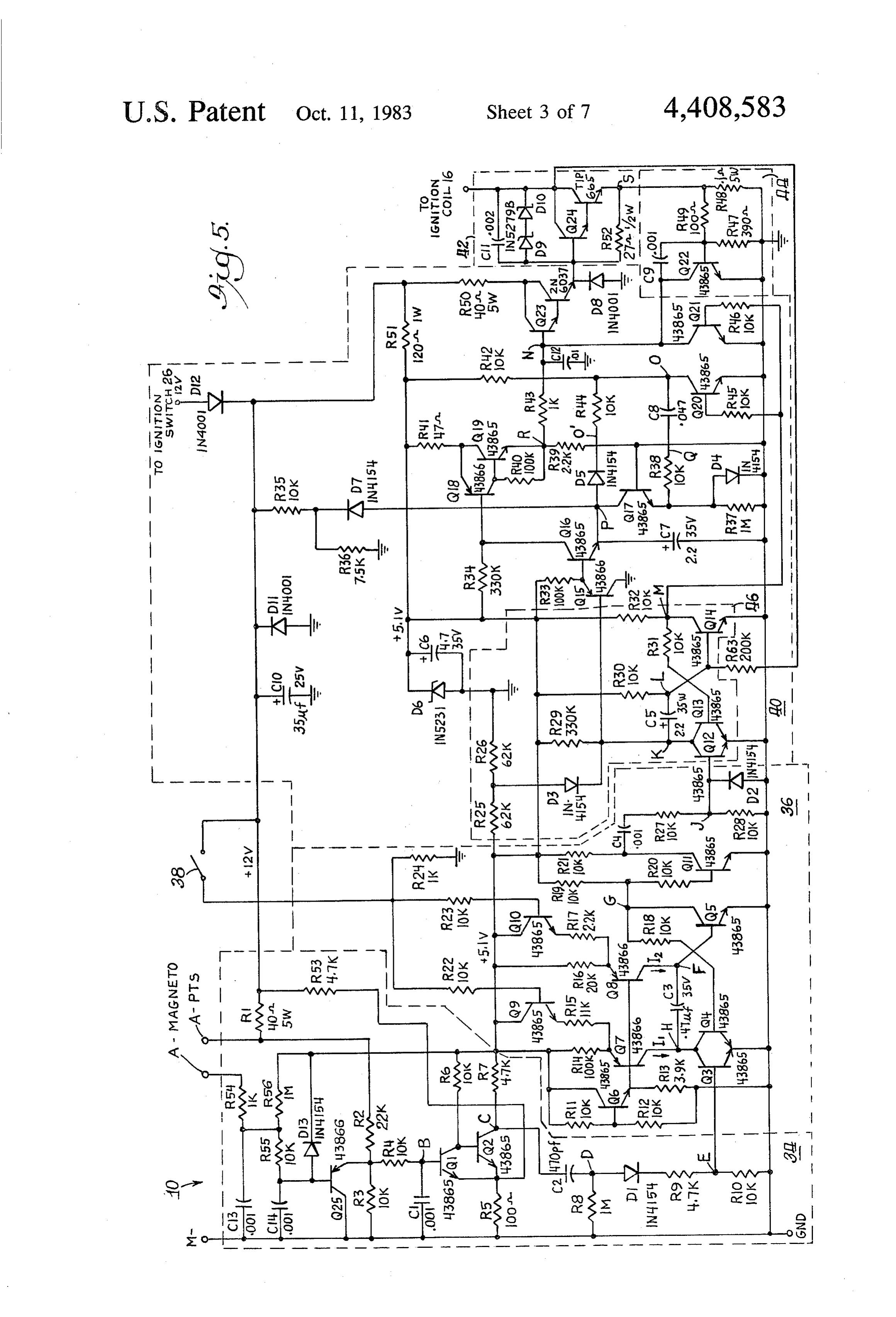
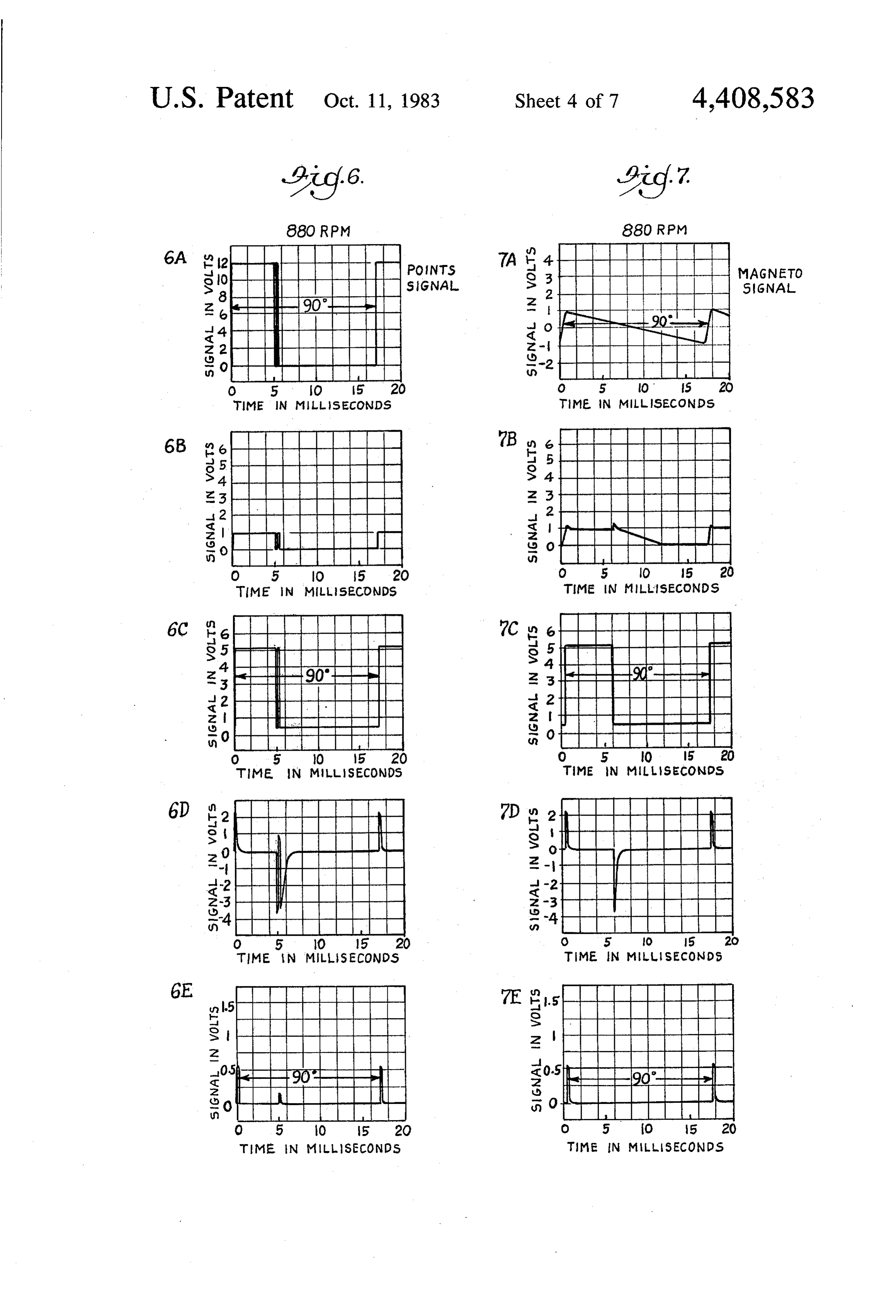
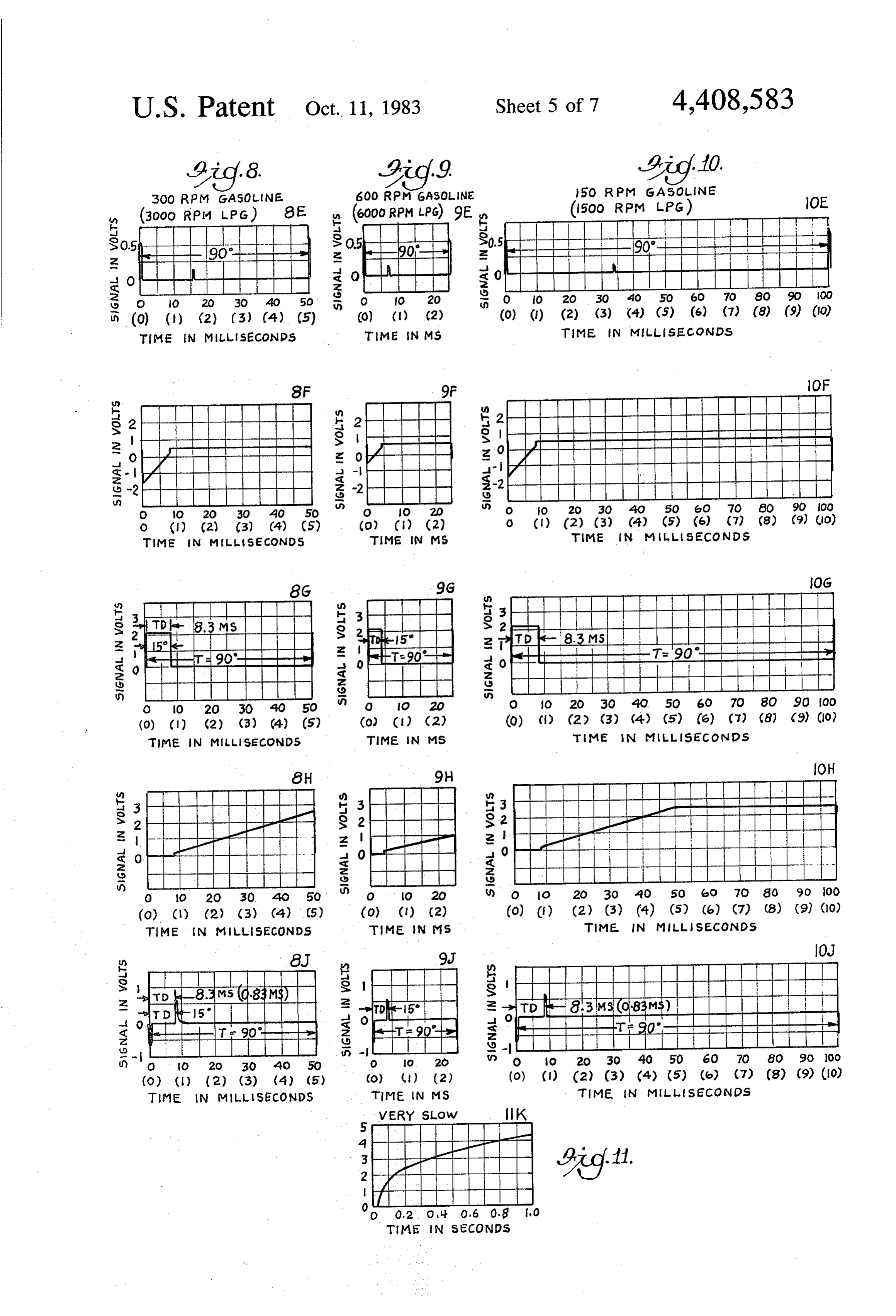
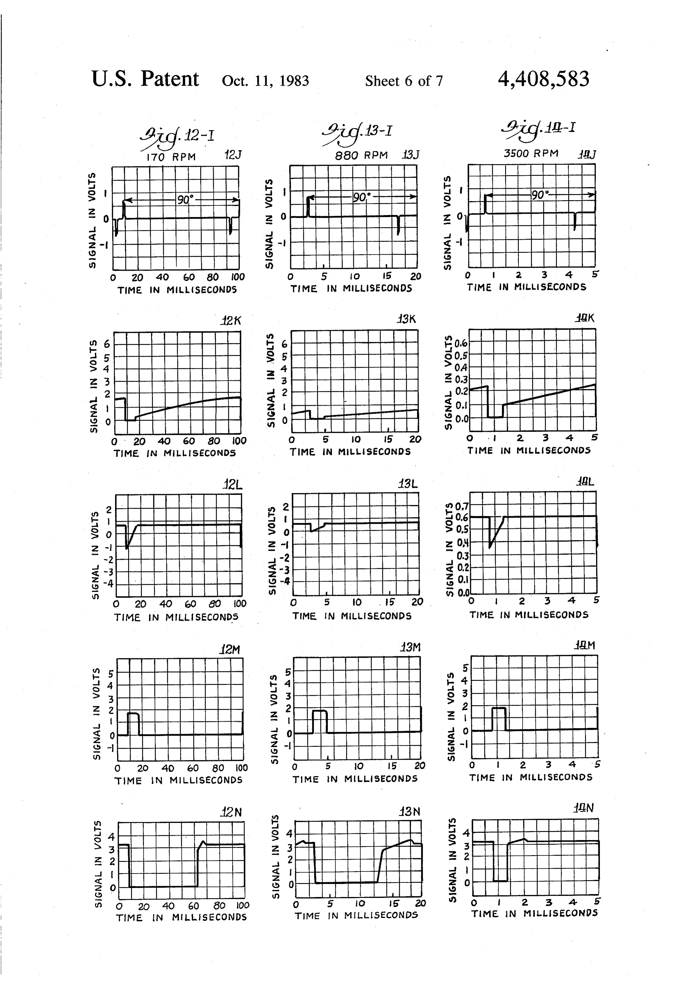
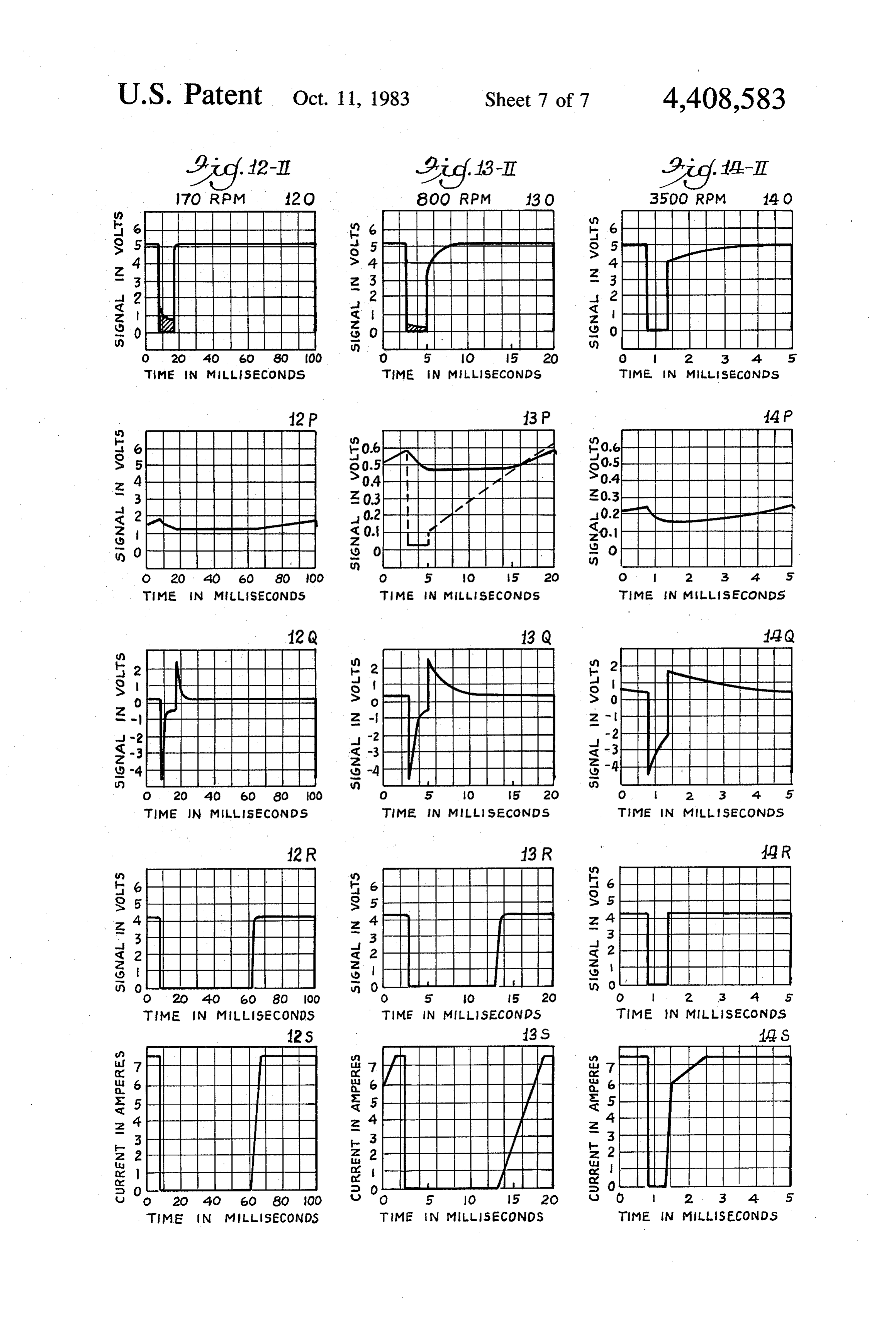
grammed timing advance for LPG in in accordance In a conventional ignition system the timing signal with the present invention; generator 22 may comprise a cam operated breaker FIG. 4 is a graph illustrating the development of a 5 point device driven from the engine 14 through the programmed timing advance for CNG in accordance programmed timing control 24 for timed opening of a with the present invention; switch in synchronism with engine rotation. That is, the FIG. 5 is a circuit diagram of a preferred embodiment breaker points separate at particular positions of the of the ignition system shown in FIG. 2 incorporating a engine cycle. The breaker points are connected be timing retard circuit and a variable dwell circuit in 20 tween the primary of the ignition coil 16 and ground in accordance with the present invention; conventional ignition, systems, so that each time the FIGS. 6A-6E are an illustration of waveforms of breaker points separate, current through the primary of signals at respective points A-E of the circuit shown in the ignition coil is interrupted, causing a high voltage to FIG. 5 for timing signals developed from breaker points be developed in the secondary of the ignition coil. The at an engine speed of 880 rpm; 25 secondary is electrically connected to the rotor 30 of FIGS. 7A-7E are an illustration of waveforms of the distributor 20. The rotor 30 is mechanically driven signals at respective points A-E of the circuit shown in by the engine 14 through the programmed timing con FIG. 5 for timing signals developed from a magneto at trol 24. This drives the rotor 30 at a speed correspond an engine speed of 880 rpm; ing to engine speed, and hence in synchronism with the FIGS. 8E-8 are an illustration of waveforms of 30 timing signals from the timing signal generator 22. The signals at respective points E-J of the circuit shown in rotation of the rotor 30 connects the secondary of the FIG. 5 at an engine speed of 300 rpm in the gasoline ignition coil 16 to successive distributor contacts 32, mode and at 3000 rpm in the LPG mode; which are in turn connected to respective terminals of FIGS. 9E-9J are an illustration of waveforms of respective spark plugs 18. The other terminals of the signals at respective points E-J of the circuit shown in 35 spark plugs 18 are grounded. - . . .. FIG. 5 at an engine speed of 600 rpm in the gasoline In the operation of the conventional ignition system, mode and at 6000 rpm in the LPG mode; the timing signal generator 22 breaks the circuit of the FIGS. 10E-10J are an illustration of waveforms of primary winding of the ignition coil 16 at particular signals at respective points E-J of the circuit shown in times in the engine cycle, hence causing high voltage to FIG. 5 at an engine speed of 150 rpm in the gasoline 40 appear at the secondary of the ignition coil 16. These mode and at 1500 rpm in the LPG mode; high voltage pulses are applied by the rotor 30 through FIG. 11 is an illustration of the waveform of the respective successive contacts 32 of the distributor 20 to signal at the point K of the circuit shown in FIG. 5 at a the respective spark plugs 18, generating sparks at the very low engine speed; respective times as determined by the timing signal FIGS. 12-I(J-N) and 12-II(O-S) are illustration of the 45 generator 22. The breaker points are thereafter closed waveforms of the signals at respective points J-S of the for a dwell time during which the current in the pri circuit shown in FIG. 5 at an engine speed of 170 rpm; mary of the ignition coil 16 is reestablished for supply FIGS. 13-I(J-N) and 13-II(O-S) are an illustration of ing energy for a subsequent spark.
the waveforms of the signals at respective points J-S of The programmed timing control 24 conventionally the circuit shown in FIG. 5 at an engine speed of 880 50 comprises a centrifugal control formed of centrifugal rpm; and weights and springs that operate to vary the position of FIGS. 14-I(J-N) and 14-II(O-S) are an illustration of the rotor 30 relative to the position of the engine 14 as the waveforms of the signals at respective points J-S of a function of engine speed. More particularly, as it is the circuit shown in FIG. 5 at an engine speed of 3500 desirable and conventional that the spark be advanced rpm. 55 at higher engine speeds because of the shorter time FIG. 1 illustrates typical desired programmed timing between ignition and top dead center at high engine advances before top dead center as functions of engine speeds, the programmed timing control operates to speeds for typical engines using different fuels, specifi advance the timing signal generator 22 relative to en cally gasoline, LPG and CNG. Conventional gasoline gine position as speed increases, in order that the spark engine ignition systems are set up for the distributor to be advanced as a function of engine speed. provide the programmed timing advance as shown by The ignition system 12 as thus far described in con the GASOLINE ADVANCE curve for gasoline. In nection with FIG. 2 comprises a conventional ignition accordance with the present invention, a programmed system as used to provide the typical timing advance as incremental advance is added to the normal GASO a function of engine speed for engines burning gasoline. LINE ADVANCE to provide programmed timing 65 That is, the system as thus far described produces the advance for the alternative fuels, as shown by the programmed timing curve GASOLINE ADVANCE curves LPGADVANCE and CNG ADVANCE. An as shown for gasoline in FIG. 1. To provide a pro ignition system in accordance with the present inven grammed timing advance for alternative fuels the igni
Page 11
tion timing control circuit 10 is interposed between the shown in FIG. 2. As shown in FIG. 3, the timing retard timing signal generator 22 and the primary of the igni circuit 36 provides one of two programmed ignition tion coil 16. retard intervals, GASOLINE RETARD and LPG As shown in FIG. 2, the ignition timing control cir RETARD. These are selectable by operation of the cuit 10 includes a signal conditioning circuit 34 which control switch 38. Each of these programmed retard receives the timing signals from the timing signal gener intervals provides a particular programmed retard as a ator 22 and acts in response to such timing signals to function of engine speed. The line identified as DIS produce relatively sharp electronic pulses correspond TRIBUTOR OFFSET signifies the offset provided by ing to respective signals from the timing signal genera mechanical adjustment of the programmed timing con tor 22. That is, each time the breaker points are sepa 10 trol 24. The programmed timing retard increment pro rated, a corresponding pulse is produced by the signal vided by the timing retard circuit 36 and the mechanical conditioning circuit 34. Alternatively, if the timing sig adjustment combine with the advance as originally nal generator includes a magneto, a corresponding pulse provided with the engine by the programmed timing is produced by the signal conditioning circuit 34 at a control 24 to produce the respective programmed tim particular point in the cycle of the magneto. 15 ing advance as shown in FIG. 3 by the curves modified The pulses from the signal conditioning circuit 34 are GASOLINE ADVANCE and LPGADVANCE.
applied to a timing retard circuit 36 which operates to More specifically, the programmed GASOLINE produce corresponding delayed pulses, delayed accord ADVANCE curve as shown in FIG. 1, and as provided ing to one programmed incremental retard when gaso by the programmed timing control 24 as it comes with line is the fuel, and in accordance with another incre 20 the engine, is combined with the DISTRIBUTOR mental timing retard when another fuel is used. The OFFSET and a respective one of the programmed difference in the two amounts of retard is the pro retard intervals to provide a timing advance appropriate grammed difference in the two programmed timing for a particular fuel. For example, the programmed advances for the respective fuels. It is only possible to MODIFIED GASOLINE ADVANCE curve as delay pulses, not advance them, relative to the pulses 25 shown in FIG. 3 is provided by adding the GASO from the signal conditioning circuit 34. Therefore, to LINE ADVANCE curve shown in FIG. 1 (and repro obtain an effective advance, which is what is desired, a duced as the ORIGINAL GASOLINE ADVANCE mechanical offset advance is applied by mechanically curve in FIG. 3) to the DISTRIBUTOR OFFSET adjusting the programmed timing control 24, and the shown in FIG. 3, and then the GASOLINE RETARD programmed advance is effected by subtracting from 30 increment is subtracted therefrom, resulting in the such advance. The mechanical offset is easy enough to MODIFIED GASOLINE ADVANCE curve shown achieve with standard timing controls, as one of the in FIG. 3, which differs from the GASOLINE AD adjustments therein is a mechanical adjustment to adjust VANCE curves shown in FIG. 1 only at very low rpm. the basic timing advance. For example, the pro Similarly the LPGADVANCE curve is produced by grammed timing control 34 may be manually offset by 35 combining the ORIGINAL GASOLINE ADVANCE, 15 to provide an additional 15 of advance; then the the DISTRIBUTOR OFFSET and the LPG RE timing retard circuit 36 may retard the pulses from the TARD curves.
advanced pulses produced in the timing signal genera Comparison of the LPGADVANCE curve shown tor 22. In the case of the gasoline timing advance, the in FIG. 3 with the LPGADVANCE curve shown in timing retard circuit 36 provides delayed pulses which 40 FIG. 1 demonstrates that the timing retard circuit 36 return the programmed timing advance to that of the provides a suitable advance from the GASOLINEAD original typical gasoline timing advance curve. For the VANCE curve as to approximate the desired LPG case where 15' advance has been introduced, the timing ADVANCE curve. It may be noted that the timing retard circuit provides 15 delay for gasoline timing. advanced curves produced by the timing retard circuit The timing retard for the alternative fuel is then less, 45 36 differ somewhat from the desired programmed ad hence providing an effective additional advance rela vance curves below 1000 rpm. As 1000 rpm is approxi tive to the gasoline timing advance curve. Which timing mately idle for conventional engines, this makes rela advance is utilized is determined by operation of a con tively little difference, particularly as each of the curves trol switch 38. is relatively flat below 1000 rpm anyway. There is a The output of the timing retard circuit 36 is applied to 50 sharp break in the gasoline advance curve at about 300 a variable dwell circuit 40. The variable dwell circuit 40 rpm but this is so far below idle as to be of no particular provides a signal for turning on the current through the consequence. All that is necessary below idle is that the primary of the induction coil 16 at an appropriate time timing be sufficient to permit the engine to start. Once in advance of its being interrupted in order that appro started, it operates at idle. No power is demanded of the priate energy may be introduced into the ignition coil so 55 engine under those circumstances except, of course, the that subsequent interruption of the current produces the power necessary to turn the engine over. desired spark. The variable dwell circuit 40 provides FIG. 4 illustrates the similar generation of the CNG signals for both turning on and turning off the current ADVANCE curve, which is obtained by adding the through the primary of the ignition coil 16 in response ORIGINAL GASOLINE ADVANCE, the DIS to the signals from the timing retard circuit 36. The 60 TRIBUTOR OFFSET and the CNG : RETARD signals from the variable dwell circuit 40 are applied to curves. The CNG RETARD curve is generated in the an output switch 42 connected to effect such switching same fashion as the LPG RETARD curve, using differ of the current. The output switch 42 switches the cur ent components, as discussed further below. rent through a current limiter circuit 44, which operates For an understanding of how the ignition timing to limit the current through the primary of the ignition 65 control circuit 10 operates to develop the programmed coil 16 to an appropriate level. timing advance curves shown in FIGS. 3 and 4, refer Reference to FIG. 3 will provide a general under ence is made to the detailed circuit of the ignition timing standing of the operation of the ignition system 12 control circuit 10 as shown in FIG. 5, and to the wave
Page 12
forms developed at respective points in the circuit. A the point E will be 90° apart in respect to engine rota preferred embodiment of the circuit comprises the com tion.
ponents as identified and connected as shown in FIG. 5. It may be noted in waveform 6A that a parasitic pulse As shown in FIG. 5, the timing signal from the timing occurs following the closing of the breaker points. This signal circuit 22 is applied to the signal conditioning is occasioned by contact bounce on closure. The pulse is circuit 34 at a terminal A-PTS if the signal is produced carried forward to succeeding points B, C, D and E; see by breaker points and at a terminal A-MAGNETO if waveforms 6B, 6C, 6D and 6E. However, by the time it the signal is produced by a magneto. Waveforms for reaches point E, it has been much attenuated, mostly in various points in the signal conditioning circuit 34 are passing the capacitor C2 and the diode D1, so that at the shown in FIG. 6 when the input is from breaker points O point E it is of small magnitude compared to the pulse and in FIG. 7 when the input is from a magneto. The occasioned by opening of the breaker points. Indeed, it waveforms in both figures are for an engine speed of is made so small as not to be able to trigger the timing 880 rpm. If a breaker point signal is applied, the signal retard circuit 36. There is no such parasitic pulse when will be in the form shown by waveform 6A. If a mag there is a magneto input.
neto signal is applied, the signal will be in the form 15 The timing retard circuit 36 as shown in FIG. 5 in shown by waveform 7A. As the signal at the input cludes a one shot multivibrator comprised of transistors terminal A-PTS is created by the opening and closing of Q3, Q4 and Q5 and a capacitor C3. Power is supplied the breaker points, the signal is at ground until the from the +5.1 v bus to the transistors Q3 and Q4 points open, at which time the terminal A-PTS is driven through a resistor R14 and a transistor Q7. The collec to +12 v through a resistor R1 from a -- 12 v bus. The 20 tors of transistors Q3 and Q4 are connected to one side -- 12 v bus receives its potential from the ignition switch of the capacitor C3, the other side of which is con 26 through a diode D12. The -- 12 v is developed across nected to the base of the transistor Q5. Power is sup a smoothing capacitor C10 and a diode D11. The signal plied to the transistor Q5 from the +5.1 v bus through at the terminal A-PTS is applied to a voltage divider a resistor R19. The collector of the transistor Q5 is formed by resistors R2 and R3, and that portion of the 25 connected to the base of the transistor Q4 through a signal developed across the resister R3 is applied resistor R18. The other side of the capacitor C3 is con through a resistor R4 to a point B to produce a signal as nected to the +5.1 v bus through a resistor R16 and a shown by wave-form 6B. A capacitor C1 is connected transistor Q8.
between the point B and ground.
Should the timing signal generator 22 take the form 30 Resistors R11, R12 and R13 and a transistor Q6 con of a magneto, the magneto signal may be applied at the stitute a source of stable bias potential for the transistors Q7 and Q8. That is, the resistors R11 and a R12 are terminal A-MAGNETO through a network comprised connected of resistors R54, R55 and R56, capacitors C13 and C14, developinginaseries between the +5.1 v bus and ground, predetermined fixed potential at their a diode D13 and a transistor Q25 to develop a corre junction. This potential is applied sponding signal at the point B, as shown by waveform 35 transistor Q6, thereby causing the to the base of the voltage across the 7B. resistor R13 to be substantially equal to that across the The signal at the point B is applied through a transis resistor R12. With resistors R11 and R12 of equal resis tor Q1 to a transistor Q2, both of which are biased by a tance, this voltage will be about 2.5 v. The consequence voltage developed across a resistor R5 through a resis of such biasing of the transistors Q7 and Q8 is that when tor R53 from the -- 12 v bus. Power for the transistors 40 these transistors conduct at all, they conduct respective Q1 and Q2 is applied through resistors R6 and R7, re constant currents I and I2 as determined by their re spectively, from a --5.1 V bus. The --5.1 v is developed spective resistors across a zener diode D6 through a resistor R51 from the they conduct such R14 and R16. When they conduct, current as to cause the voltage drops -- 12 v bus. A capacitor C6 is connected across the diode D6. When the signal applied at the point B goes 45 across the respective resistors R14 and R16 as would positive, it turns on the transistor Q1, which in turn put the potentials at their emitters slightly above the turns off the transistor Q2. Hence, opening of the points bias potential of 2.5 v. With the components shown, I at the point A-PTS causes the output of the transistor isperes. about 25 microamperes, and I2 is about 125 microam Q2 at a point C to go positive as shown by waveform 6C. Alternatively, with magneto input, the signal at the 50 Assuming the multivibrator to be in its quiescent state point C takes the form illustrated by waveform 7C. when a pulse at the point E is applied to the base of the The signal from the point C is applied through a transistor Q3, the transistor Q3 conducts, discharging capacitor C2 to a point D which is connected to ground the capacitor C3 and driving the base of the transistor through a resistor R8. The capacitor C2 thus passes Q5 low. This turns off the transistor Q5, hence raising only the AC component of the signal at the point B to 55 the potential of the base of the transistor Q4, keeping produce the signal shown by waveform 6D for a that transistor on even after the pulse that initially breaker points input and by waveform 7D for a mag turned on the transistor Q3 has dissipated. With the one side of the capacitor C3 thus grounded, the capacitor neto input.
This signal is applied through a diode D1 across a C3 is charged by the constant current I2 through the voltage divider comprised of resistors R9 and R10. The 60 transistor Q8 until the potential at a point F, the base of diode D1 serves to cut off the negative portion of the the transistor Q5, reaches a potential sufficiently above signal developed at the point D to produce a signal at a ground as to enable the transistor Q5 to turn on. This point E as shown by waveform 6E for a breaker points terminates the period of the multivibrator as it lowers input and by waveform 7E for a magneto input. This is the potential of a point G, the collector of the transistor the signal output from the signal conditioning circuit 34 65 Q5, to ground potential, hence acting through the resis and is applied to the timing retard circuit 36. With an 8 tor R18 to turn off the transistor Q4. Constant current cylinder engine, as shown in this example, and operat I then flows through the resistor R14 and the transistor ing at substantially constant speed, the output pulses at Q7 at a constant rate to charge the capacitor C3 oppo
Page 13
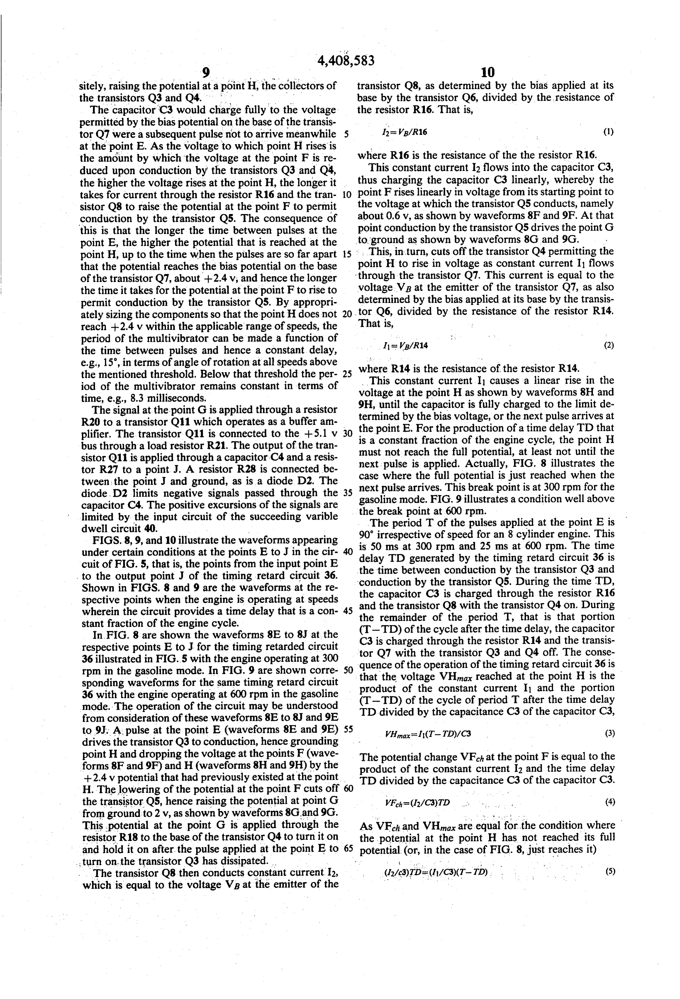
sitely, raising the potential at a point H, the collectors of transistor Q8, as determined by the bias applied at its the transistors Q3 and Q4. base by the transistor Q6, divided by the resistance of The capacitor C3 would charge fully to the voltage the resistor R16. That is, permitted by the bias potential on the base of the transis 12= VB/R16 (1) tor Q7 were a subsequent pulse not to arrive meanwhile at the point E. As the voltage to which point H rises is where R16 is the resistance of the the resistor R16. the amount by which the voltage at the point F is re duced upon conduction by the transistors Q3 and Q4, thus This constant current 2 flows into the capacitor C3, the higher the voltage rises at the point H, the longer it point charging the capacitor C3 linearly, whereby the takes for current through the resistor R16 and the tran 10 Frises linearly in voltage from its starting point to sistor Q8 to raise the potential at the point F to permit the voltage at which the transistor Q5 conducts, namely about 0.6 v, as shown by waveforms 8F and 9F. At that conduction by the transistor Q5. The consequence of point conduction by the transistor Q5 drives the point G this is that the longer the time between pulses at the point E, the higher the potential that is reached at the to ground as shown by waveforms 8G and 9G. point H, up to the time when the pulses are so far apart 15 This, in turn, cuts off the transistor Q4 permitting the that the potential reaches the bias potential on the base point H to rise in voltage as constant current I1 flows of the transistor Q7, about +2.4v, and hence the longer through the transistor Q7. This current is equal to the the time it takes for the potential at the point F to rise to voltage VB at the emitter of the transistor Q7, as also permit conduction by the transistor Q5. By appropri determined by the bias applied at its base by the transis ately sizing the components so that the point H does not 20 tor Q6, divided by the resistance of the resistor R14. reach +2.4 v within the applicable range of speeds, the That is, period of the multivibrator can be made a function of I = VB/R14 (2) the time between pulses and hence a constant delay, e.g., 15, in terms of angle of rotation at all speeds above where R14 is the resistance of the resistor R14. the mentioned threshold. Below that threshold the per 25 This constant current. I causes a linear rise in the iod of the multivibrator remains constant in terms of time, e.g., 8.3 milliseconds. voltage at the point H as shown by waveforms 8H and The signal at the point G is applied through a resistor 9H, until the capacitor is fully charged to the limit de termined by the bias voltage, or the next pulse arrives at
R20 to a transistor Q11 which operates as a buffer am plifier. The transistor Q11 is connected to the +5.1 v 30 the point E. For the production of a time delay TD that bus through a load resistor R21. The output of the tran ismust a constant fraction of the engine cycle, the point H not reach the full potential, at least not until the sistor Q11 is applied through a capacitor C4 and a resis next pulse tor R27 to a point J. A resistor R28 is connected be case whereistheapplied. full
Actually, FIG. 8 illustrates the potential is just reached when the tween the point J and ground, as is a diode D2. The next pulse arrives. This break point is at 300 rpm for the diode. D2 limits negative signals passed through the 35 gasoline mode. FIG. 9 illustrates a condition well above capacitor C4. The positive excursions of the signals are the break point at 600 rpm.
limited by the input circuit of the succeeding varible The period T of the pulses applied at the point E is dwell circuit 40.
FIGS. 8,9, and 10 illustrate the waveforms appearing 90 irrespective of speed for an 8 cylinder engine. This under certain conditions at the points E to J in the cir delay ms
TD generated by the timing retard circuit 36 is cuit of FIG. 5, that is, the points from the input point E the time between conduction by the transistor Q3 and to the output point J of the timing retard circuit 36. "conduction by the transistor Q5. During the time TD, Shown in FIGS. 8 and 9 are the waveforms at the re spective points when the engine is operating at speeds and the capacitor C3 is charged through the resistor R16 wherein the circuit provides a time delay that is a con 45 the the transistor Q8 with the transistor Q4 on. During remainder of the period T, that is that portion stant fraction of the engine cycle. (T-TD) of the cycle after the time delay, the capacitor In FIG. 8 are shown the waveforms 8E to 8J at the respective points E to J for the timing retarded circuit tor isQ7charged
C3 through the resistor R14 and the transis with the transistor Q3 and Q4 off. The conse 36 illustrated in FIG.5 with the engine operating at 300 quence rpm in the gasoline mode. In FIG. 9 are shown corre 50 that theofvoltage the operation of the timing retard circuit 36 is VHna reached at the point H is the sponding waveforms for the same timing retard circuit product of the constant current I and the portion 36 with the engine operating at 600 rpm in the gasoline (T-TD) of the cycle of period T after the time delay mode. The operation of the circuit may be understood TD divided by the capacitance C3 of the capacitor C3, from consideration of these waveforms 8E to 8J and 9E to 9.J. A. pulse at the point E (waveforms 8E and 9E) 55 VH=(T-TD)/C3 (3) drives the transistor Q3 to conduction, hence grounding point H and dropping the voltage at the points F (wave The potential change VFch at the point F is equal to the forms 8F and 9F) and H (waveforms 8H and 9H) by the product of the constant current I2 and the time delay +2.4 v potential that had previously existed at the point TD divided by the capacitance C3 of the capacitor C3. H. The lowering of the potential at the point F cuts off 60 the transistor Q5, hence raising the potential at point G VF=(12/C3)TD (4) from ground to 2v, as shown by waveforms 8G and 9G.
This potential at the point G is applied through the As VF-hand VHmax are equal for the condition where resistor R18 to the base of the transistor Q4 to turn it on the potential at the point H has not reached its full and hold it on after the pulse applied at the point E to 65 potential (or, in the case of FIG. 8, just reaches it) turn on the transistor Q3 has dissipated.
. The transistor Q8 then conducts constant current 12, which is equal to the voltage Vb at the emitter of the
Page 14
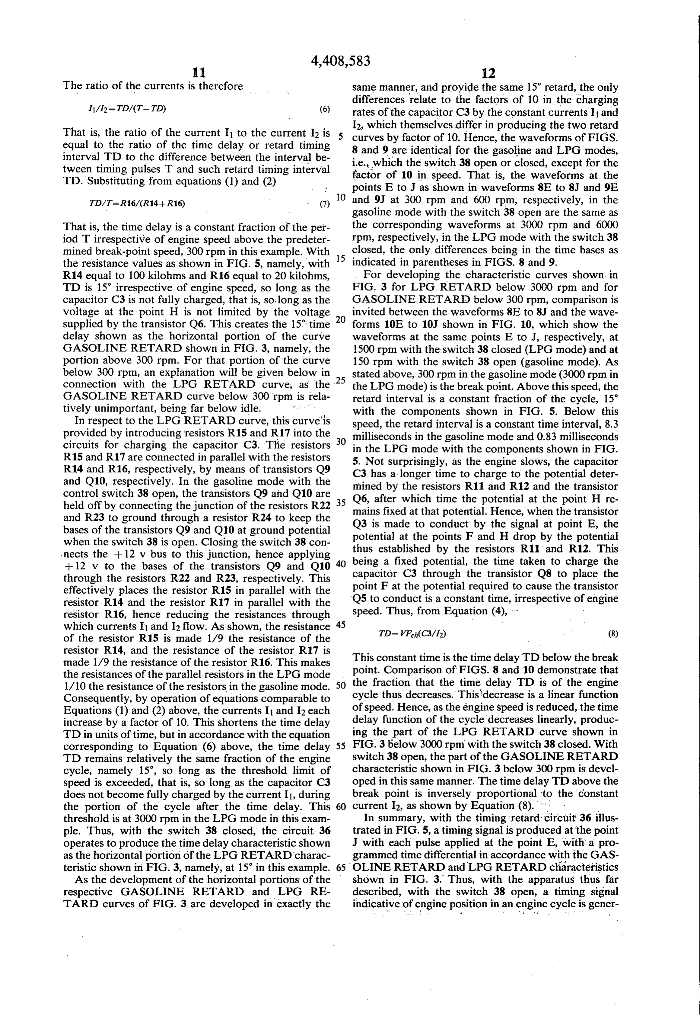
The ratio of the currents is therefore same manner, and provide the same 15 retard, the only
differences relate to the factors of 10 in the charging rates of the capacitor C3 by the constant currents I and
I2, which themselves differ in producing the two retard
That is, the ratio of the current I to the current I2 is curves equal to the ratio of the time delay or retard timing 8 and 9byarefactor of 10. Hence, the waveforms of FIGS. interval TD to the difference between the interval be i.e., which the switchfor identical the gasoline and LPG modes, tween timing pulses T and such retard timing interval factor of 10 in speed.38That open or closed, except for the is, the waveforms at the
TD. Substituting from equations (1) and (2) points E to J as shown in waveforms 8E to 8J and 9E O and 9J at 300 rpm and 600 rpm, respectively, in the
gasoline mode with the switch 38 open are the same as
That is, the time delay is a constant fraction of the per the corresponding waveforms at 3000 rpm and 6000 iod T irrespective of engine speed above the predeter rpm, respectively, in the LPG mode with the switch 38 mined break-point speed, 300 rpm in this example. With 15 closed, the only differences being in the time bases as the resistance values as shown in FIG. 5, namely, with indicated in parentheses in FIGS. 8 and 9. R14 equal to 100 kilohms and R16 equal to 20 kilohms, For developing the characteristic curves shown in TD is 15 irrespective of engine speed, so long as the FIG. 3 for LPG. RETARD below 3000 rpm and for capacitor C3 is not fully charged, that is, so, long as the GASOLINE, RETARD below 300 rpm, comparison is voltage at the point H is not limited by the voltage invited between the waveforms 8E to 8J and the wave supplied by the transistor Q6. This creates the 15 time forms 10E to 10J shown in FIG. 10, which show the delay shown as the horizontal portion of the curve waveforms at the same points E to J, respectively, at GASOLINE RETARD shown in FIG. 3, namely, the 1500 rpm with the switch 38 closed (LPG mode) and at portion above 300 rpm. For that portion of the curve 150 rpm with the switch 38 open (gasoline mode). As below 300 rpm, an explanation will be given below in 25 stated above, 300 rpm in the gasoline mode (3000 rpm in connection with the LPG RETARD curve, as the the LPG mode) is the breakpoint. Above this speed, the GASOLINE RETARD curve below 300 rpm is rela retard interval is a constant fraction of the cycle, 15 tively unimportant, being far below idle. s. . . . . . with the components shown in FIG. 5. Below this In respect to the LPG RETARD curve, this curve is speed, the retard interval is a constant time interval, 8.3 provided by introducing resistors R15 and R17 into the milliseconds in the gasoline mode and 0.83 milliseconds circuits for charging the capacitor C3. The resistors 30 in the LPG mode with the components shown in FIG. R15 and R17 are connected in parallel with the resistors 5. Not surprisingly, as the engine slows, the capacitor R14 and R16, respectively, by means of transistors Q9 and Q10, respectively. In the gasoline mode with the C3 has a longer time to charge to the potential deter mined by the resistors R11 and R12 and the transistor control switch 38 open, the transistors Q9 and Q10 are 35 Q6, after held off by connecting the junction of the resistors R22 mains fixedwhich time the potential at the point H re at that potential. Hence, when the transistor and R23 to ground through a resistor R24 to keep the Q3 is made to conduct by the signal at point E, the bases of the transistors Q9 and Q10 at ground potential potential at the points F and H drop by the potential when the switch 38 is open. Closing the switch 38 con thus established by the resistors R11 and R12. This nects the -- 12 v bus to this junction, hence applying being a fixed potential, the time taken to charge the - 12 v to the bases of the transistors Q9 and Q10 capacitor C3 through the transistor Q8 to place the through the resistors R22 and R23, respectively. This point F at the potential required to cause the transistor effectively places the resistor R15 in parallel with the resistor R14 and the resistor R17 in parallel with the Q5 to conduct is a constant time, irrespective of engine resistor R16, hence reducing the resistances through speed. Thus, from Equation (4), which currents I and I2 flow. As shown, the resistance 45 TD= VF(C3/12) (8) of the resistor R15 is made 1/9 the resistance of the resistor R14, and the resistance of the resistor R17 is made 1/9 the resistance of the resistor R16. This makes This constant time is the time delay TD below the break the resistances of the parallel resistors in the LPG mode point. Comparison of FIGS. 8 and 10 demonstrate that 1/10 the resistance of the resistors in the gasoline mode. SO the fraction that the time delay TD is of the engine Consequently, by operation of equations comparable to cycle thus decreases. This decrease is a linear function Equations (1) and (2) above, the currents I and I2 each of speed. Hence, as the engine speed is reduced, the time increase by a factor of 10. This shortens the time delay delay function of the cycle decreases linearly, produc TD in units of time, but in accordance with the equation ing the part of the LPG RETARD curve shown in corresponding to Equation (6) above, the time delay 55 FIG. 3 below 3000 rpm with the switch 38 closed. With TD remains relatively the same fraction of the engine switch 38 open, the part of the GASOLINE RETARD cycle, namely 15, so long as the threshold limit of characteristic shown in FIG. 3 below 300 rpm is devel speed is exceeded, that is, so long as the capacitor C3 oped in this same manner. The time delay TD above the does not become fully charged by the current I1, during break point is inversely proportional to the constant the portion of the cycle after the time delay. This 60 current I2, as shown by Equation (8). threshold is at 3000 rpm in the LPG mode in this exam In summary, with the timing retard circuit 36 illus ple. Thus, with the switch 38 closed, the circuit 36 trated in FIG. 5, a timing signal is produced at the point operates to produce the time delay characteristic shown J with each pulse applied at the point E, with a pro as the horizontal portion of the LPGRETARD charac grammed time differential in accordance with the GAS teristic shown in FIG. 3, namely, at 15 in this example. 65 OLINE RETARD and LPG RETARD characteristics As the development of the horizontal portions of the shown in FIG. 3. Thus, with the apparatus thus far respective GASOLINE RETARD and LPG RE described, with the switch 38 open, a timing signal
TARD curves of FIG. 3 are developed in exactly the indicative of engine position in an engine cycle is gener
Page 15
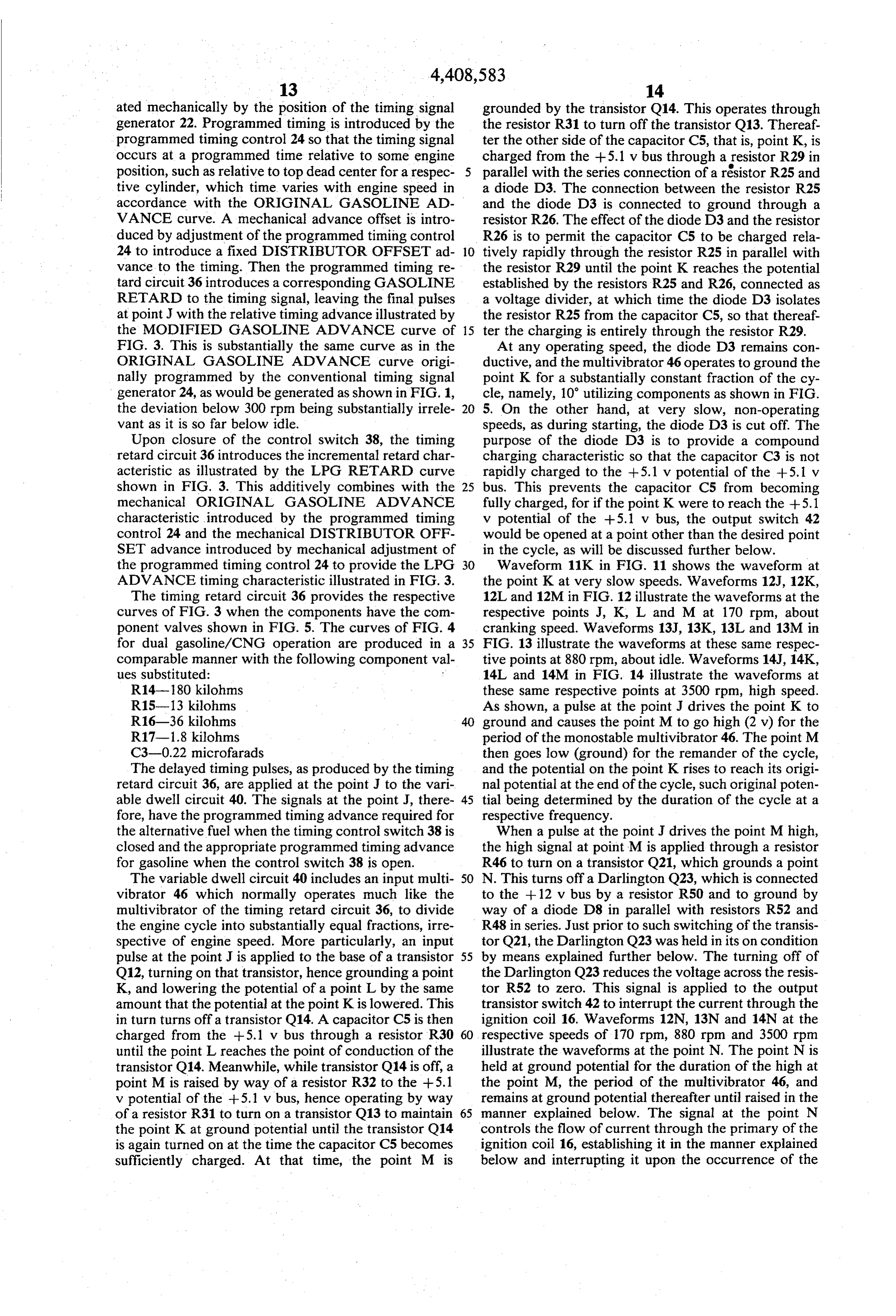
ated mechanically by the position of the timing signal grounded by the transistor Q14. This operates through generator 22. Programmed timing is introduced by the the resistor R31 to turn off the transistor Q13. Thereaf programmed timing control 24 so that the timing signal ter the other side of the capacitor C5, that is, point K, is occurs at a programmed time relative to some engine charged from the +5.1 v bus through a resistor R29 in position, such as relative to top dead center for a respec parallel with the series connection of a resistor R25 and tive cylinder, which time varies with engine speed in a diode D3. The connection between the resistor R25 accordance with the ORIGINAL GASOLINE AD and the diode D3 is connected to ground through a VANCE curve. A mechanical advance offset is intro resistor R26. The effect of the diode D3 and the resistor duced by adjustment of the programmed timing control R26 is to permit the capacitor C5 to be charged rela 24 to introduce a fixed DISTRIBUTOR OFFSET ad 10 tively rapidly through the resistor R25 in parallel with vance to the timing. Then the programmed timing re the resistor R29 until the point K reaches the potential tard circuit 36 introduces a corresponding GASOLINE established by the resistors R25 and R26, connected as RETARD to the timing signal, leaving the final pulses a voltage divider, at which time the diode D3 isolates at point J with the relative timing advance illustrated by the resistor R25 from the capacitor C5, so that thereaf. the MODIFIED GASOLINE ADVANCE curve of 15 ter the charging is entirely through the resistor R29. FIG. 3. This is substantially the same curve as in the At any operating speed, the diode D3 remains con ORIGINAL GASOLINE ADVANCE curve origi ductive, and the multivibrator 46 operates to ground the nally programmed by the conventional timing signal point K for a substantially constant fraction of the cy generator 24, as would be generated as shown in FIG. 1, cle, namely, 10 utilizing components as shown in FIG. the deviation below 300 rpm being substantially irrele 5. On the other hand, at very slow, non-operating vant as it is so far below idle. speeds, as during starting, the diode D3 is cut off. The Upon closure of the control switch 38, the timing purpose of the diode D3 is to provide a compound retard circuit 36 introduces the incremental retard char charging characteristic so that the capacitor C3 is not acteristic as illustrated by the LPG RETARD curve rapidly charged to the +5.1 v potential of the +5.1 v shown in FIG. 3. This additively combines with the 25 bus. This prevents the capacitor C5 from becoming mechanical ORIGINAL GASOLINE ADVANCE fully charged, for if the point K were to reach the +5.1 characteristic introduced by the programmed timing v potential of the +5.1 v bus, the output switch 42 control. 24 and the mechanical DISTRIBUTOR OFF would be opened at a point other than the desired point SET advance introduced by mechanical adjustment of in the cycle, as will be discussed further below. the programmed timing control 24 to provide the LPG 30 Waveform 11K in FIG. 11 shows the waveform at ADVANCE timing characteristic illustrated in FIG. 3. the point K at very slow speeds. Waveforms 12J, 12K, The timing retard circuit 36 provides the respective 12L and 12M in FIG. 12 illustrate the waveforms at the curves of FIG. 3 when the components have the com respective points J, K, L and M at 170 rpm, about ponent valves shown in FIG. 5. The curves of FIG. 4 cranking speed. Waveforms 13J, 13K, 13L and 13M in for dual gasoline/CNG operation are produced in a 35 FIG. 13 illustrate the waveforms at these same respec comparable manner with the following component val tive points at 880 rpm, about idle. Waveforms 14J, 14K, ues substituted: 14L and 14M in FIG. 14 illustrate the waveforms at R14-180 kilohms these same respective points at 3500 rpm, high speed. R15-13 kilohms As shown, a pulse at the point J drives the point K to R16-36 kilohms ground and causes the point M to go high (2 v) for the R17-1.8 kilohms period of the monostable multivibrator 46. The point M C3-0.22 microfarads then goes low (ground) for the remander of the cycle, The delayed timing pulses, as produced by the timing and the potential on the point K rises to reach its origi retard circuit 36, are applied at the point J to the vari nal potential at the end of the cycle, such original poten able dwell circuit 40. The signals at the point J, there 45 tial being determined by the duration of the cycle at a fore, have the programmed timing advance required for respective frequency.
the alternative fuel when the timing control switch 38 is When a pulse at the point J drives the point M high, closed and the appropriate programmed timing advance the high signal at point M is applied through a resistor for gasoline when the control switch 38 is open. R46 to turn on a transistor Q21, which grounds a point The variable dwell circuit 40 includes an input multi 50 N. This turns off a Darlington Q23, which is connected vibrator 46 which normally operates much like the to the -- 12 v bus by a resistor R50 and to ground by multivibrator of the timing retard circuit 36, to divide way of a diode D8 in parallel with resistors R52 and the engine cycle into substantially equal fractions, irre R48 in series. Just prior to such switching of the transis spective of engine speed. More particularly, an input tor Q21, the Darlington Q23 was held in its on condition pulse at the point J is applied to the base of a transistor 55 by means explained further below. The turning off of Q12, turning on that transistor, hence grounding a point the Darlington Q23 reduces the voltage across the resis K, and lowering the potential of a point L by the same tor R52 to zero. This signal is applied to the output amount that the potential at the point K is lowered. This transistor switch 42 to interrupt the current through the in turn turns off a transistor Q14. A capacitor C5 is then ignition coil 16. Waveforms 12N, 13N and 14N at the charged from the +5.1 v bus through a resistor R30 respective speeds of 170 rpm, 880 rpm and 3500 rpm until the point L reaches the point of conduction of the illustrate the waveforms at the point N. The point N is transistor Q14. Meanwhile, while transistor Q14 is off, a held at ground potential for the duration of the high at point M is raised by way of a resistor R32 to the +5.1 the point M, the period of the multivibrator 46, and v potential of the +5.1 v bus, hence operating by way remains at ground potential thereafter until raised in the of a resistor R31 to turn on a transistor Q13 to maintain 65 manner explained below. The signal at the point N the point K at ground potential until the transistor Q14 controls the flow of current through the primary of the is again turned on at the time the capacitor C5 becomes ignition coil 16, establishing it in the manner explained sufficiently charged. At that time, the point M is below and interrupting it upon the occurrence of the
Page 16
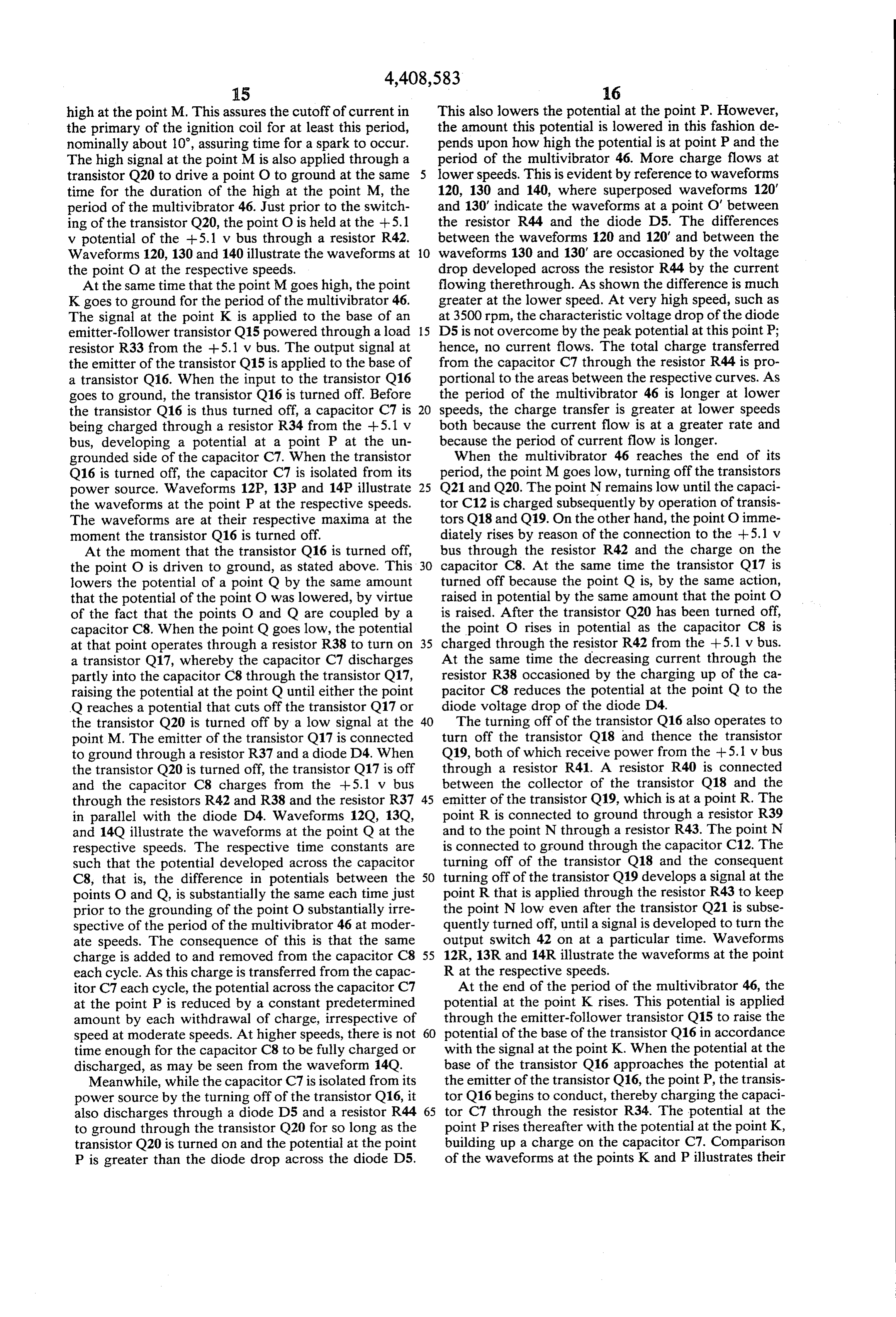
high at the point M. This assures the cutoff of current in This also lowers the potential at the point P. However, the primary of the ignition coil for at least this period, the amount this potential is lowered in this fashion de nominally about 10, assuring time for a spark to occur. pends upon how high the potential is at point P and the The high signal at the point M is also applied through a period of the multivibrator 46. More charge flows at transistor Q20 to drive a point O to ground at the same lower speeds. This is evident by reference to waveforms time for the duration of the high at the point M, the 120, 130 and 140, where superposed waveforms 120' period of the multivibrator 46. Just prior to the switch and 130' indicate the waveforms at a point O' between ing of the transistor Q20, the point O is held at the +5.1 the resistor R44 and the diode D5. The differences v potential of the -5.1 v bus through a resistor R42. between the waveforms 120 and 120' and between the Waveforms 120, 130 and 140 illustrate the waveforms at 10 waveforms 130 and 130' are occasioned by the voltage the point O at the respective speeds. drop developed across the resistor R44 by the current At the same time that the point M goes high, the point flowing therethrough. As shown the difference is much K goes to ground for the period of the multivibrator 46. greater at the lower speed. At very high speed, such as The signal at the point K is applied to the base of an at 3500 rpm, the characteristic voltage drop of the diode emitter-follower transistor Q15 powered through a load 15 D5 is not overcome by the peak potential at this point P; resistor R33 from the +5.1 v bus. The output signal at hence, no current flows. The total charge transferred the emitter of the transistor Q15 is applied to the base of from the capacitor C7 through the resistor R44 is pro a transistor Q16. When the input to the transistor Q16 portional to the areas between the respective curves. As goes to ground, the transistor Q16 is turned off. Before the period of the multivibrator 46 is longer at lower the transistor Q16 is thus turned off, a capacitor C7 is 20 speeds, the charge transfer is greater at lower speeds being charged through a resistor R34 from the --5.1 v both because the current flow is at a greater rate and bus, developing a potential at a point P at the un because the period of current flow is longer. grounded side of the capacitor C7. When the transistor When the multivibrator 46 reaches the end of its Q16 is turned off, the capacitor C7 is isolated from its period, the point M goes low, turning off the transistors power source. Waveforms 12P, 13P and 14P illustrate 25 Q21 and Q20. The point N remains low until the capaci the waveforms at the point P at the respective speeds. tor C12 is charged subsequently by operation of transis The waveforms are at their respective maxima at the tors Q18 and Q19. On the other hand, the point O imme moment the transistor Q16 is turned off. diately rises by reason of the connection to the --5.1 v At the moment that the transistor Q16 is turned off, bus through the resistor R42 and the charge on the the point O is driven to ground, as stated above. This 30 capacitor C8. At the same time the transistor Q17 is lowers the potential of a point Q by the same amount turned off because the point Q is, by the same action, that the potential of the point O was lowered, by virtue raised in potential by the same amount that the point O of the fact that the points O and Q are coupled by a is raised. After the transistor Q20 has been turned off, capacitor C8. When the point Q goes low, the potential the point O rises in potential as the capacitor C8 is at that point operates through a resistor R38 to turn on 35 charged through the resistor R42 from the +5.1 v bus. a transistor Q17, whereby the capacitor C7 discharges At the same time the decreasing current through the partly into the capacitor C8 through the transistor Q17, resistor R38 occasioned by the charging up of the ca raising the potential at the point Q until either the point pacitor C8 reduces the potential at the point Q to the Q reaches a potential that cuts off the transistor Q17 or diode voltage drop of the diode D4. the transistor Q20 is turned off by a low signal at the 40 The turning off of the transistor Q16 also operates to point M. The emitter of the transistor Q17 is connected turn off the transistor Q18 and thence the transistor to ground through a resistor R37 and a diode D4. When Q19, both of which receive power from the +5.1 v bus the transistor Q20 is turned off, the transistor Q17 is off through a resistor R41. A resistor R40 is connected and the capacitor C8 charges from the +5.1 v bus between the collector of the transistor Q18 and the through the resistors R42 and R38 and the resistor R37 45 emitter of the transistor Q19, which is at a point R. The in parallel with the diode D4. Waveforms 12O, 13O, point R is connected to ground through a resistor R39 and 14Q illustrate the waveforms at the point Q at the and to the point N through a resistor R43. The point N respective speeds. The respective time constants are is connected to ground through the capacitor C12. The such that the potential developed across the capacitor turning off of the transistor Q18 and the consequent C8, that is, the difference in potentials between the 50 turning off of the transistor Q19 develops a signal at the points O and Q, is substantially the same each time just point R that is applied through the resistor R43 to keep prior to the grounding of the point O substantially irre the point N low even after the transistor Q21 is subse spective of the period of the multivibrator 46 at moder quently turned off, until a signal is developed to turn the ate speeds. The consequence of this is that the same output switch 42 on at a particular time. Waveforms charge is added to and removed from the capacitor C8 55 12R, 13R and 14R illustrate the waveforms at the point each cycle. As this charge is transferred from the capac R at the respective speeds.
itor C7 each cycle, the potential across the capacitor C7 At the end of the period of the multivibrator 46, the at the point P is reduced by a constant predetermined potential at the point K rises. This potential is applied amount by each withdrawal of charge, irrespective of through the emitter-follower transistor Q15 to raise the speed at moderate speeds. At higher speeds, there is not 60 potential of the base of the transistor Q16 in accordance time enough for the capacitor C8 to be fully charged or with the signal at the point K. When the potential at the discharged, as may be seen from the waveform 14O. base of the transistor Q16 approaches the potential at Meanwhile, while the capacitor C7 is isolated from its the emitter of the transistor Q16, the point P, the transis power source by the turning off of the transistor Q16, it tor Q16 begins to conduct, thereby charging the capaci also discharges through a diode D5 and a resistor R44 65 tor C7 through the resistor R34. The potential at the to ground through the transistor Q20 for so long as the point Prises thereafter with the potential at the point K, transistor Q20 is turned on and the potential at the point building up a charge on the capacitor C7. Comparison P is greater than the diode drop across the diode D5. of the waveforms at the points K and P illustrates their
Page 17
relationship. The peak potential at the point P is neces point S indicates the maximum allowable current, the sarily reached at the moment the potential at the point transistor Q22 conducts. The transistor Q22 controls the K goes low, cutting off the transistor Q16. The peak signal at the point N at such value as to prevent the thus identifies the timing signal for interrupting current signal at the point S from rising above the voltage limit through the primary of the ignition coil 16 to cause a signifying the current limit. In this case a suitable cur spark in a respective cylinder. At constant speed, the rent limit is 7.5 amperes. This is higher than is permitted peak occurs at the same point in each cycle. The point in conventional ignition coils, because the current where the transistor Q16 starts to conduct depends through the ignition coil is held off by the variable upon the level of the potential at the point Q after dwell circuit 40 for a longer period of time than in charge has been removed as well as upon the potential 10 standard ignition systems. This permits a higher current at the point K. At all operating speeds, the potential at to be present at the time of current interruption because the point K rises linearly as a function of time, as is current is not flowing through such a large portion of shown by waveforms 13K and 14.K. At moderate the cycle and hence is not heating the ignition coil to speeds the charge removed from the capacitor C8 is a such an extent, it being the heating of the coil that is constant. Hence, the point of conduction of the transis 15 generally the limiting factor. Typically, current is lim tor Q16 is a substantially constant time interval prior to ited to 4 amperes in standard ignition coils with stan the switching off of the transistor Q165 at moderate dard ignitions.
speeds. At high speeds, the amount of charge removed The variable dwell circuit 40 operates at different is less, and consequently the point of conduction is not times following a spark to turn on the current in the so long before the switching. 20 primary of the ignition coil 16 to build up the current in When the transistor Q16 conducts to charge the ca the ignition coil 16 for providing sufficient energy to pacitor C7, a potential is developed across the resistor cause a spark when the current is interrupted. As it is R34 which causes the transistor Q18 to conduct, in turn desirable that the current not flow unnecessarily in the causing the transistor Q19 to conduct. This develops a ignition coil, as would result in unnecessary heating of high signal at the point R, thereby applying a positive 25 the coil and unnecessary power loss, it is desirable that signal to the point N, turning on the Darlington Q23, the current not turn on immediately after the spark, but and hence turning on the output transistor switch 42 to rather only sufficiently before the next spark as to pro cause current to flow through the primary of the igni vide appropriate energy in the ignition coil 46 at the tion coil 16. The signal at the point N, as illustrated by time of current interruption. At slower speeds it is desir waveforms 12N, 13N and 14N for the respective speeds, 30 able to turn on the current for a longer period in ad thus determines the timing of the turning off and on of vance of the spark than at higher speeds, because at current through the primary of the ignition coil 16. higher speeds there is residual current in the coil after As a voltage must be developed across the resistor the spark has fired and the current is turned back on. R34 to turn on the transistor Q18, it is essential that the That is, at high speeds there is insufficient time for all of potential at the point Knot reach +5.1 v. It is for this 35 the energy to be dissipated in a spark and some energy reason that the diode D3 decouples the point K from remains in the ignition coil 16, hence not requiring the the resistor R25 at high potentials, as described above, addition of so much energy for the next firing. This is to cause the capacitor C5 to charge more slowly and achieved by the variable dwell circuit 40 as illustrated in hence cause the potential of the point K to rise more FIG. 5.
slowly, as shown by waveform 11K. This will assure In summary of the operation of the variable dwell turning on of the output transistor switch 42 in starting. circuit 40, current in the primary of the ignition coil 16 The output transistor switch 42 comprises a Darling is turned on a programmed time before each expected ton Q24 connected at its collectors to the primary of the timing signal appearing at the point J. This is based on ignition coil 16. The input from the variable dwell cir the reasonable assumption that succeeding cycles of cuit 40 is applied to the Darlington Q24 across the resis 45 engine operation are almost always of substantially the tor R52. Diodes D9 and D10 are connected in series same duration. It can therefore be assumed that the peak across a capacitor C11 between the collectors and the signals reached at the point K, and hence the peak sig input of the Darlington Q24 to prevent overvoltages on nals reached at the point P, remain substantially the the Darlington Q24. The resistor R52 is connected be same for successive cycles. A predetermined voltage is tween the input and the output of the Darlington Q24. 50 subtracted from the peak signal reached at the point P in The input of the Darlington Q24 is applied to the cur one cycle to establish a dwell reference signal at the rent limiter circuit 44 at a point S. point P for the next cycle. When the magnitude of sig The current limiter circuit 44 includes a resistor R48 nal at the point K reaches the magnitude of the dwell through which the ignition coil current flows for devel reference signal at the point P, the current is reestab oping a control voltage at the point S indicative of such 55 lished through the primary of the ignition coil 16, and current. Waveforms 12S, 13S and 14S illustrate the the magnetic field builds up in the ignition coil. In the waveforms at the point S at the respective speeds, and variable dwell circuit 40 illustrated, the signal at the hence ignition current flow at the respective speeds. point Krises linearly with time at all operating speeds. The voltage at the point S is applied through a resis Further, at moderate speeds, the predetermined voltage tor R49 to the base of a transistor Q22. A resistor R47 is that is subtracted is substantially a constant. The current coupled between the base and emitter of the transistor is therefore reestablished a substantially constant time Q22, and a capacitor C9 is connected between the base interval before the next expected timing pulse. At and collector of transistor Q22. The function of the higher speeds, the charge drawn off is less, and the time transistor Q22 is to control the voltage at the point N so interval is therefore shorter, so that not so much time is as to limit the current through the resistor R48 to the 65 available for reestablishing the field. However, as the desired value of current limit in the primary of the field is not entirely dissipated at high speeds, it is unnec ignition coil 16. That is, the resistors R47 and R49 com essary to provide so much time to reestablish it. At very prise a voltage divider such that when the voltage at the low speeds, as in cranking, it is desired to provide more
Page 18
time for reestablishing the field in order to assure that of engine position in an engine cycle, means responsive the field be entirely established so that a hot spark, can to said timing signal for initiating a spark in a respective be assured, it being more important to assure adequate cylinder of the engine, and programmed timing control sparks in starting a cold engine. r means responsive to engine speed for controlling the The collectors of the Darlington Q24 are connected 5 occurrence of said timing signal relative to engine posi to the point L through a resistor R63. The effect of this tion in systematic relation to engine speed to provide is to charge the capacitor C5 more rapidly when the such spark at a timing angle appropriate for a first fuel ignition coil 16 is turned off for long periods as in the at each respective engine speed: a timing control for an case of a misfire. In the event of misfire, it is desirable to alternative fuel comprising means responsive to engine turn the current back on sooner so as not to dissipate the 10 speed for producing a controlled timing angle interval energy wastefully. A misfire will occur when one of the systematically related to engine speed, and means re leads to the spark plugs is broken or falls off. In such sponsive to said controlled timing angle interval and case the voltage across the capacitor C11 rises rapidly said timing signal for changing the timing angle of such and the diodes D9 and D10 conduct so as to limit the voltage. This would dissipate energy in the ignition coil, 15 spark by said controlled timing angle interval to pro not only wasting energy but perhaps impeding subse vide such spark at a timing angle appropriate for a sec quent firing, particularly at high speeds where there is a ond2. A fuel at each respective engine speed. timing control according to claim 1 wherein said very short time for current to be reestablished, reliance means for producing a controlled timing angle interval being placed on the fact that in normal operation the includes advance means for producing a fixed advance energy is not fully dissipated upon each firing. With the 20 timing angle interval, retard means for producing a feedback to the point L, the higher voltage developed retard timing angle interval advances the charging of the capacitor C5 to shorten engine speed, and means for systematicallycombining related to said advance the period of the multivibrator 46, hence hastening the and retard timing angle intervals to produce said con turning back on of the current through the primary of trolled timing angle interval.
the ignition coil 16 before all the energy is dissipated. 25 3. A timing control according to claim 2 wherein said Although a preferred embodiment of the invention has been shown and described with particularity, vari aretard means comprises a one shot multivibrator having period substantially equal to said retard interval.
ous changes in the circuit may be made within the scope 4. A timing control according to claim 2 wherein said of the present invention. For example, a voltage divider formed by resistors R35 and R36 may be connected 30 that is means retard provides a retard timing angle interval a substantially constant fraction of the engine between ground and the -- 12 v bus, with the junction of cycle at engine speeds above a predetermined engine two resistors connected to the point P by a diode D7. speed and is a substantially constant time interval at This operates to assure that the voltage at the point P not rise above the potential at the junction of the resis engine speeds below said predetermined engine speed. tors R35 and R36. This circuit is effective in cold 35 5. A timing control according to claim 2 wherein said weather for starting with a low battery. Under low retard means includes sources of first and second con battery conditions the junction of the resistors R35 and stant currents, and means responsive to said first and R36 is low. When this voltage is below the potential second constant currents for producing a retard timing that would otherwise exist at the point P, the charge on angle interval that bears such ratio to the difference the capacitor C7 is leaked off through the resistor R36, 40 between the timing angle interval between timing sig having advancing the time for turning on the output nals and said retard timing angle interval as the magni switch 42 so as to provide more time for current to build tude of said first constant current bears to the magni up in the coil 16 when the battery is low. This assures tude of said second constant current at engine speeds that a larger current be built up in the coil 16 to make above a predetermined engine speed and is a substan certain that a spark will be created when the current is 45 tially constant time interval inversely proportional to interrupted, even though the battery is low. the magnitude of said second constant current at engine As another alternative, the components of the timing speeds below said predetermined engine speed. retard circuit 36 may permit switching of timing for 6. A timing control according to claim 5 including more than two fuels, as all three of gasoline, LPG and switch means for selectively switching the magnitude of CNG. 50 at least one of said constant currents to change the What is claimed is: systematic relationship between said controlled timing 1. For use in an ignition system for a spark ignited angle interval and engine speed to provide such spark at internal combustion engine having a plurality of cylin a time appropriate for a fuel other than said second fuel ders, which system includes timing means responsive to at each respective engine speed.
engine position for producing a timing signal indicative 55 s: k 3: k
Page 19
UNITED STATES PATENT AND TFRADEMARK OFFICE
CERTIFICATE OF CORRECTION
INVENTOR(S) : James W. Merrick
It is certified that error appears in the above-identified patent and that said Letters Patent is hereby Corrected as shown below:
Abstract page, Item 73), change "Automatic Controls, Corp." to --Autotronic Controls, Corp. --.
Column 3 line 45, after "are" insert --an--. Column 6, line 33, change "curves" to -- curve--. Column l2, line 53, change "function" to --fraction--. Column l7, line 5l, change "input" to -- output--. Column l9, line 4l, change "having" to --hence--.
signed and sealed this
Twenty-fourth D 2 y of January 1984
SEAL
Attest:
GERALD J. MOSSINGHOFF
Attesting Officer Commissioner of Patents and Trademarks
Provenance
- Collection
- Cited prior art
- Original PDF
- patentimages.storage.googleapis.com →
- Filed
- 1981-05-26
- Pages
- 19
- Method
- pdftotext (the PDF's own text layer) + pdftoppm 300dpi page scans
- Source
- Google Patents bibliographic record
- Granted
- 1983-10-11
- Inventors
- James W. Merrick; Automatic Controls Corp
- Transcribed from
- patentimages.storage.googleapis.com →