patent · US4489564
Hydride storage for hydrogen
25 December 1984
Page 1 — bibliographic record
United States Patent (19) 11 Patent Number: 4,489,564 Häusler et al. (45) Date of Patent: Dec. 25, 1984
(54 HYDRIDE STORAGE FOR HYDROGEN 56 References Cited
(75) Inventors: Peter Häusler, Hattingen; Norbert 3,732,690 5/1973 Meijer ................................. 123/533 Nathrath, Bottrop, both of Fed. Rep. 4,135,621 1/1979 Turillon et al. ......................... 62/48 of Germany 4,165,569 8/1979 Mackay ... ... 62/48 4,187,092 2/1980 Woolley .................................. 62/48 4,383,606 5/1983 Hunter ........ ... 206/0.7 73) Assignee: Thyssen Industrie AG, Fed. Rep. of 4,393,924 7/1983 Asami et al. ............................ 62/48 Germany 4,396, 14 8/1983 Golben et al. .......................... 62/48 Primary Examiner-Ronald C. Capossela 21 Appl. No.: 488,264 Attorney, Agent, or Firm-McGlew & Tuttle
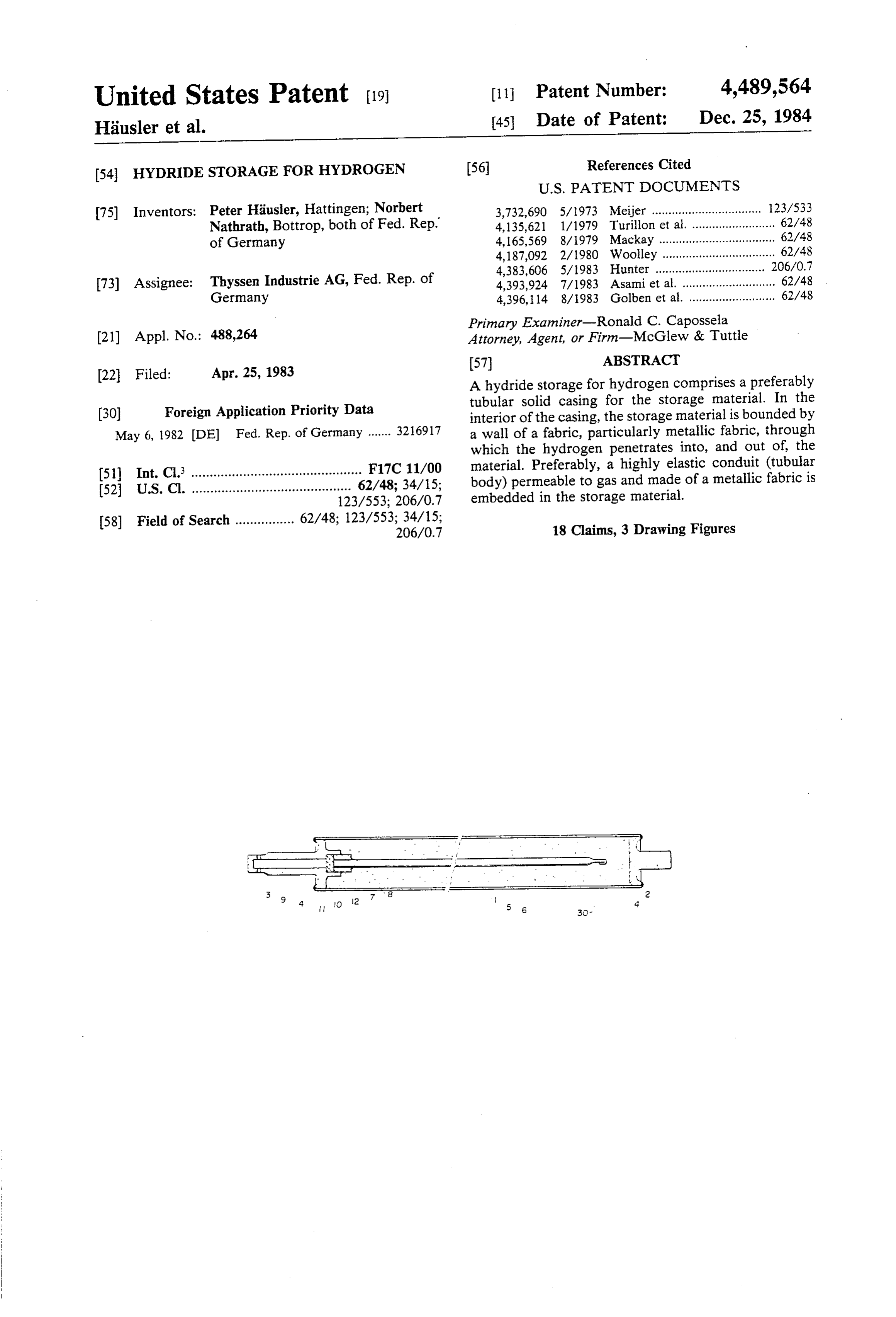
(22 Filed: Apr. 25, 1983 A hydride storage for hydrogen comprises a preferably (30) Foreign Application Priority Data tubular solid casing for the storage material. In the interior of the casing, the storage material is bounded by
May 6, 1982 (DE) Fed. Rep. of Germany ....... 3216917 a wall of a fabric, particularly metallic fabric, through which the hydrogen penetrates into, and out of, the (51) Int. Cl. .............................................. F17C 11/00 material. Preferably, a highly elastic conduit (tubular 52 U.S. Cl. ........................................... 62/48; 34/15; body) permeable to gas and made of a metallic fabric is 123/553; 206/0.7 embedded in the storage material.
58) Field of Search ................ 62/48; 123/553; 34/15; 18 Claims, 3 Drawing Figures
Page 2
Drawing sheet — no readable text.
Page 3
Drawing sheet — no readable text.
Page 4
Drawing sheet — no readable text.
Page 5
In an advantageous embodiment, the fabric is a metal
HYDRIDE STORAGE FOR HYDROGEN lic fabric. Metal fabrics are temperature resistant and make it possible to activate the storage material in the
FIELD AND BACKGROUND OF THE casing while applying higher temperatures. INVENTION 5 The fabric may also take the shape of a sleeve sur rounding
This invention relates in general to the construction being equipped the storage material and, advantageously, of storage containers and in particular to a new and with a baffle plate at the front end. useful hydride storage for hydrogen. In most instances, however, a hydride storage will be Depending on the required storage volume, even a 10 preferred the having at least one conduit extending from external connection of the casing and embedded in plurality of such storages may be combined to a larger the storage material.
unit. Hydrogen as an energy carrier can be stored and may be designed as aAccordingtubular to claim 4, this conduit body made of said fabric.
shipped either in gaseous or liquid state, or also in the To improve the charging and discharging capability form of a metal hydride. Under normal ambience condi tions, hydrogen can be stored in the metal hydride form 15 in hydride storage elements of larger dimensions, it is without problems, safely, and in a small space. In gen advantageous to utilize the fabric both as a sleeve sur eral, the storage material, such as a metal alloy contain rounding the storage material, and as a conduit embed ing titanium, zirconium, chromium, and manganese, in dedIntherein.
a hydride storage of one embodiment, the hydro the form of a powder, or of pellets (tablets), is received in elongated tubular casings having frontal and external 20 gen is distributed and passes through the tubular body connections. Most metals combine with hydrogen to made of a highly elastic fabric well permeable to gas. metal hydrides, with, as a rule, heat being released if Consequently, with usual elongated tubular casings, the hydrogen is introduced to the metal, and heat being hydrogen is introduced into and removed from the wanted to remove the hydrogen. The released or added storage material substantially only in the radial direc heat of reaction must be dissipated from, or introduced 25 tion. As the storage material expands during the charg into the storage material, depending on the direction of ing, the tubular body yields accordingly. The result is the reaction, as quickly as possible. Moreover, it must that the casing walls are less loaded, so that the varia be taken into account that during charging of the stor tions in dimensions may be provided while preserving age, i.e. adsorption of hydrogen, the storage material the same safety as before, and the total weight of the expands. To minimize the pressure and/or temperature 30 storage structure can be reduced. gradients within the storage material, it is sought to It is advisable to make the metallic fabric of stainless make all portions (partially volumes) of the storage steel wire, preferably such having a diameter of 0.04 material participate substantially uniformly in the re inn at InoSt.
spective reaction during the charging or discharging of Metal fabrics may be obtained therefrom having a the storage. 35 mesh size of the order of up to 0.04 mm, preferably 0.01 Up to the present time, this has been achieved only to to 0.02 mm. With such a small mesh size, the metallic an unsatisfactory extent with designs where the hydro fabric may in addition function as a filter, since the gen is introduced or removed at one side, particularly at passage of fine metal particles through the fabric is at the front end, of an elongated tubular casing (German least made difficult by apertures of this size. OS No. 30 22 859). It has been found particularly advantageous to use as
SUMMARY OF THE CASING
the metallic fabric a braid (lace or galloon) fabric. Such braid fabrics are made of relatively few thick wires in
The present invention is directed to providing more the warp direction, and of many thin wires in the filling Satisfactory charging and discharging conditions, and direction. They surround the storage material as a particularly to a design resulting in shorter (mean) paths 45 sleeve or tubular body exhibiting optimum properties in of flow in a casing volume filled with storage material, its stiffness in the longitudinal direction, elasticity in the and to an improved temperature and pressure distribu radial direction, mesh size, and shape of the apertures. tion. To ensure a satisfactorily stable shape of the tubular In accordance with the invention a hydride storage body before and after its insertion in the storage mate for hydrogen comprises a solid tubular casing in which 50 rial, the body is made from a flat piece of fabric by the storage material is received and which has a first bending it round and welding in the axial direction. The closed end and an opposite second closed end, an exter handling of the tubular body and its securing is simpli nal connection connected into said first closed end hav fied by fitting it at its connection end into a bushing and ing a passage for hydrogen flow, a filter in said passage, welding it thereto.
a casing extending around said tube along its length and 55 For safety reasons, an additional filter may be pro defining a boundary between the bottom of the storage vided in the inventive hydride storage, in the form of a material and said space within said casing between said disc or plate which is inserted along with the bushing in casing wall and said tube where the hydrogen can flow the external connection of the casing. Accordingly, it is freely, said tube having a wall formed of a fabric which an object of the invention to provide an improved hy is resistant to hydrogen. 60 dride storage for hydrogen. This design makes the volume of the storage material The various features of novelty which characterize body elastically variable and, advantageously, acceler the invention are pointed out with particularity in the ates the hydrogenation and hydrogen release, while claims annexed to and forming a part of this disclosure. providing an additional filtration. For a better understanding of the invention, its operat Fabrics of this kind may be made of a plastic, for 65 ing advantages and specific objects attained by its uses, example. In such instances, it is advisable to activate the reference is made to the accompanying drawings and storage material to be hydrogenated, prior to introduc descriptive matter in which preferred embodiments of ing it into the hydride storage casing. the invention are illustrated.
Page 6
as an embedded conduit 6. Conduit 6 is secured to bush
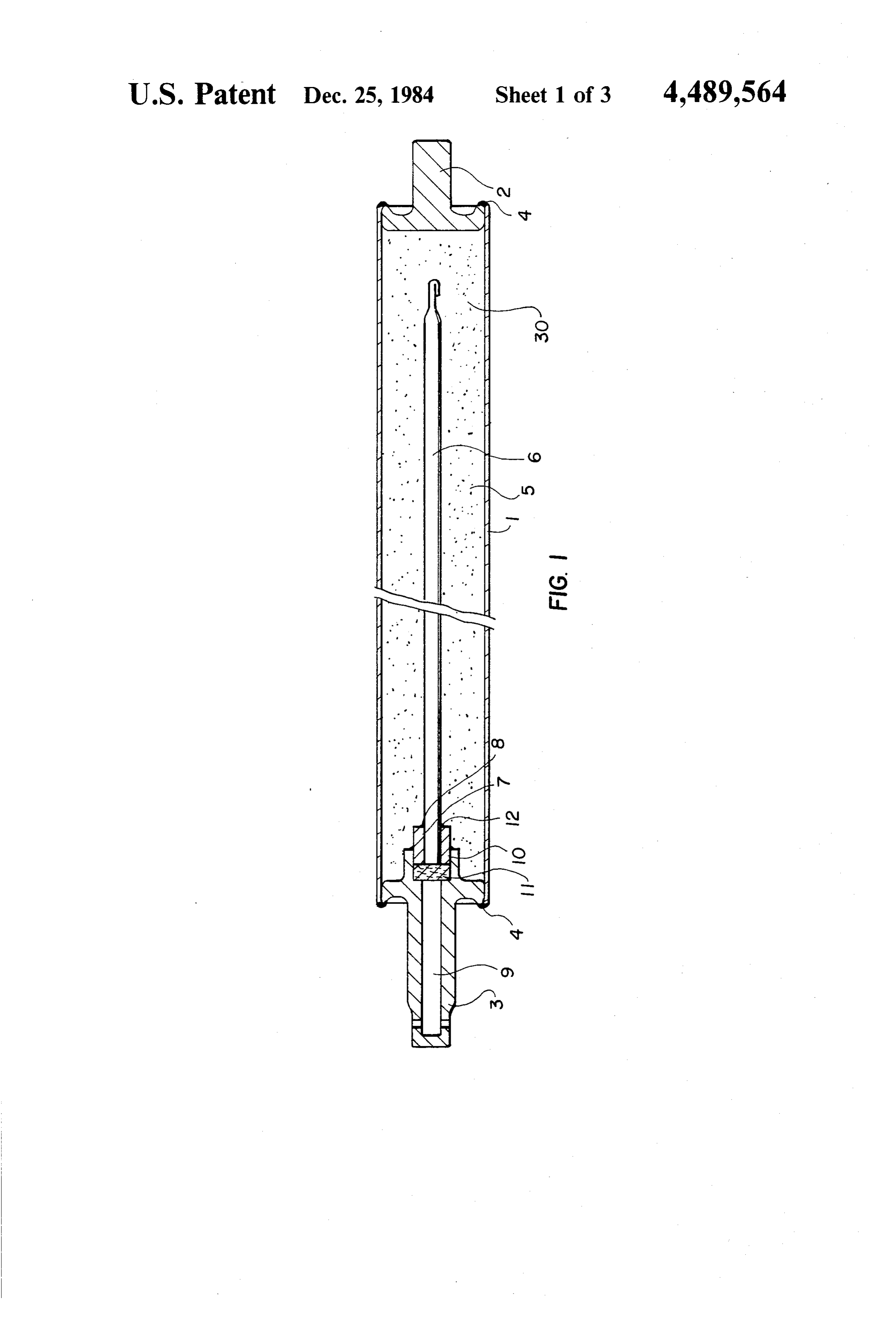
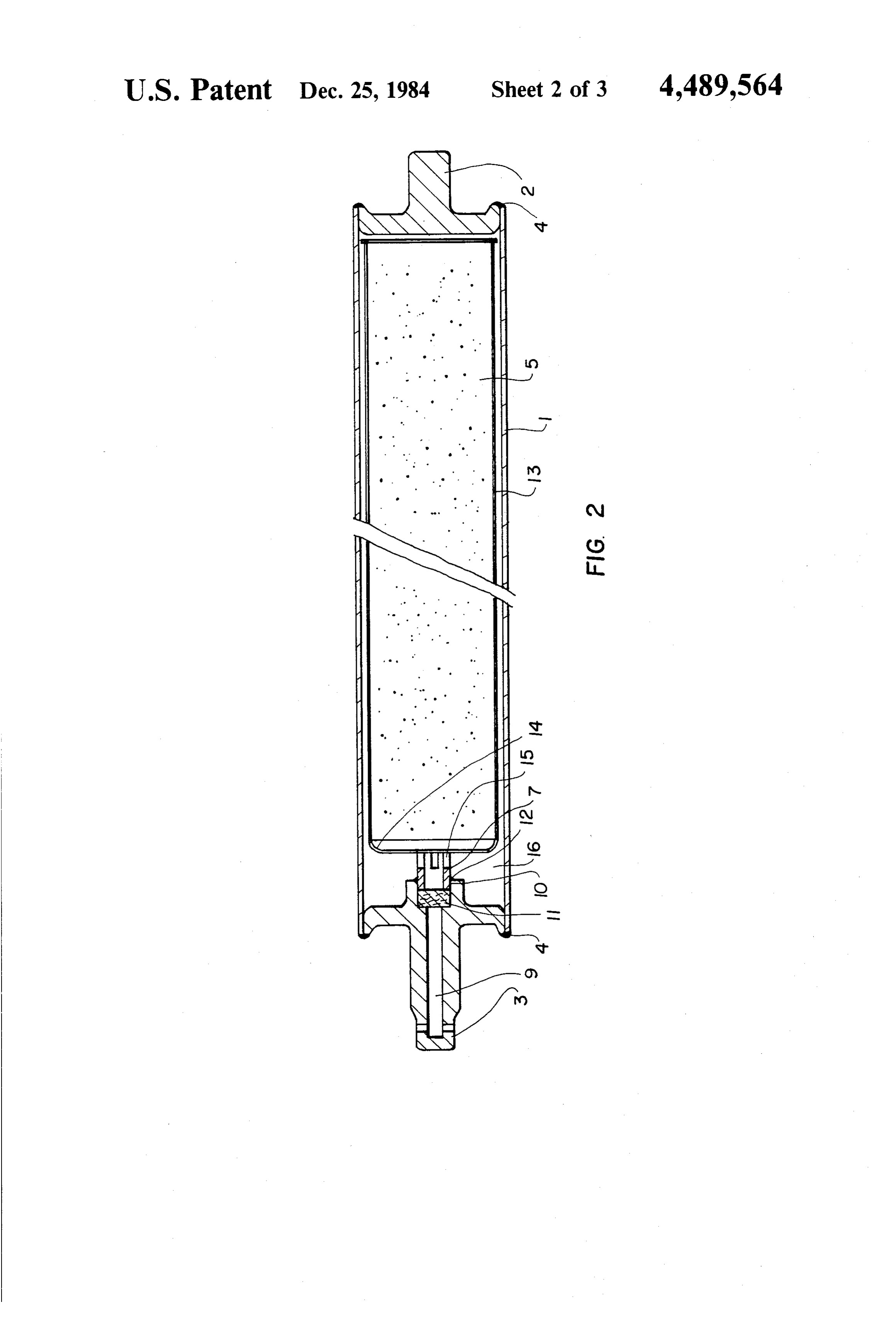
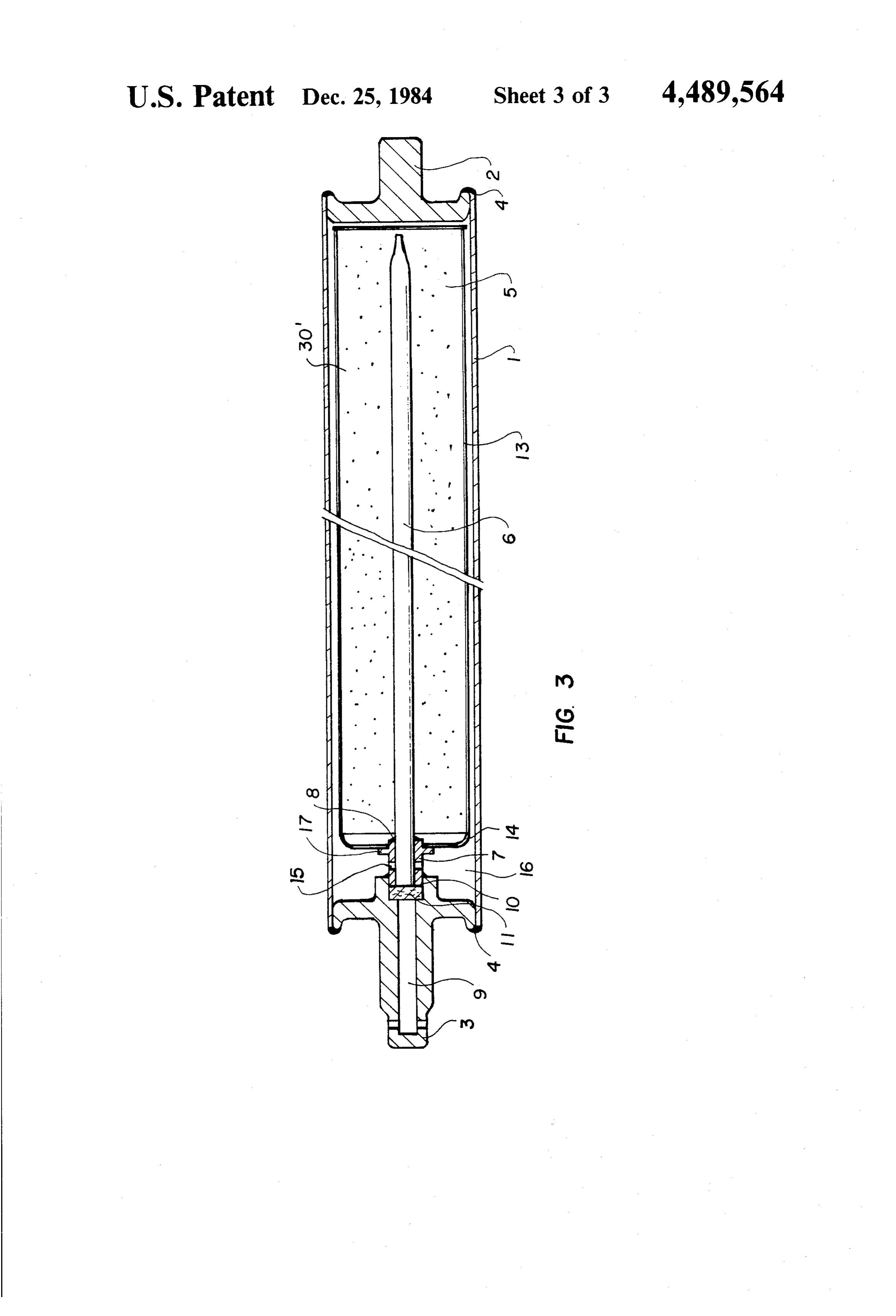
BRIEF DESCRIPTION OF THE DRAWINGS ing 7 by a circular weld 8; baffle plate 14 is supported on In the drawings: bushing 7 by a flange 17. The introduced hydrogen FIG. 1 is a longitudinal sectional view of a hydride branches downstream of filter plate 11; one part flows storage container constructed in accordance with the 5 into metal-fabric conduit 6, the other part flows through invention; slots 15 into vestibule 16 and therefrom into the gap FIG. 2 is a view similar to FIG. 1 of another embodi between solid casing 1 and sleeve 13. During a dis ment; and charge the flow is received.
FIG. 3 is a view similar to FIG. 1 of still another While specific embodiments of the invention have embodiment. O been shown and described in detail to illustrate the DESCRIPTION OF THE PREFERRED application of the principles of the invention, it will be EMBODIMENTS understood that the invention may be embodied other wise without departing from such principles.
Referring to the drawings, in particular to FIG. 1, the What is claimed is:
invention embodied therein comprises a hydride storage 15 1. A hydride storage for hydrogen comprising a rigid for hydrogen which comprises a rigid tubular casing or tubular housing containing a storage material therein housing 1 which contains a storage material 30 such as having one closed end and an opposite end with an a powdery metal and which has one end which is closed external connection, means defining a bore in said exter by a fitting plug 2 which is welded at 4 and an opposite other end with an external connection 3 and means 20 nal connection and into said housing for the flow of defining a passage including a step bore 9 and the inte hydrogen, a filter in said bore, a flexible fabric material rior of a metal braid conduit 6 for the hydrogen flow. A in the form of a tube extending axially in said housing filter 10 is in the passage and a space 5 is defined around and defining a space communicating with said bore, said the passage principally around the conduit 6 and con fabric material being resistant to hydrogen and bound tains the storage material 30. The hydrogen can flow 25 ing one axially extending surface of said storage mate rial so that hydrogen can pass into and out of said stor freely into the space 5 and the conduit 6 is formed by a age wall of a fabric material which is resistant to hydrogen pandmaterial and and so that said storage material can ex contract radially into and out of said space.
and preferably a metal fabric and from a stainless steel 2. A hydride storage according to claim 1, wherein wire having a particular mesh size.
The hydride storage shown in FIG. 1 comprises a 30 said3. fabric material is a metallic fabric. A hydride storage according to claim 2, wherein casing in the shape of a cylindrical tube 1 having its said metallic fabric is made from stainless steel wire. open ends closed by a fitting plug 2 and, on the other 4. A hydride storage according to claim 3, wherein side, by an external connection 3.
Plug 2 and connection 3 are secured to cylindrical said5. metallic fabric has a mesh size of up to 0.04 mm. A hydride storage according to claim 4, wherein tube 1 on their front edges by welds 4. The interior of 35 said mesh size is 0.01 to 0.02 mm. this casing is filled with a powdery storage metal 30. 6. A hydride storage according to claim 3, wherein Centrally within the storage metal 30, a conduit 6 is provided which is formed by a tubular body of a metal said metallic fabric is made from a steel wire having a lic braid fabric. The metallic fabric is made from stain diameter of up to 0.04 mm.
less steel wire having a maximum diameter of 0.04 mm, 40 said7. metallic
A hydride storage according to claim 6, wherein fabric is a braid fabric.
and has a mesh size of about 0.01 mm. At the connection side, conduit 6 is fitted into a bushing 7 of a steel resis 8. A hydride storage according to claim 1 wherein tant to hydrogen, and secured to the front side of the said fabric meterial in the form of a tube comprises a bushing by a circular weld 8. tubular conduit extending into said storage material, External connection 3 is provided with a stepped 45 said space defined centrally in said storage material with bore 9 having its larger-diameter portion 10 located storage material around said space.
adjacent inner space 5 of the casing. In this larger por 9. A hydride storage for hydrogen according to claim tion 10, bushing 7, fitted to conduit 6, is inserted with 8, wherein said tubular conduit extends into said con the interposition of a filter plate 11. Bushing 7 is secured nection and including a bushing in said connection en to the inside edge of connection 3 by a circular weld 12. 50 gaged around said conduit.
Filter plate 11 comprises a sintered body of chromi 10. A hydride storage according to claim 9, wherein um-nickel steel resistant to hydrogen. It is also possible, said conduit is welded into said bushing. however, to employ a filter plate of a plastic resistant to 11. A hydride storage according to claim 9, wherein hydrogen. The grade of filtration of the filter is 0.01 to said bushing and said filter are fitted into said external 0.02 mm. In the embodiment of FIG. 2, the storage 55 connection.
material in the interior 5 of the solid casing (tube 1) of 12. A hydride storage according to claim 9 wherein the hydride storage is surrounded by a sleeve 13 of a said storage material has an outer circumferential sur fabric made from steel wire having a mesh size of about face in contact with an inner surface of said rigid tubu 0.02 mm. At the front side of sleeve 13, a baffle plate 14 lar housing, is provided. Bushing 7 fitted in connection 3 has three 60 13. A hydride storage according to claim 12 wherein slots 15 providing communication between bore 9 and a said fabric material comprises a metallic fabric made vestibule 16. The other reference numerals are the same from stainless steel wire having a diameter up to 0.04 as in FIG. 1. Sleeve 13 surrounding the storage material mn, said metallic fabric having a mesh size of between is accommodated in casing 1 with only little play, yet 0.01 and 0.02 mm.
without affecting the free flow of hydrogen there- 65 14. A hydride storage according to claim 1 wherein around. said flexible fabric material extends around said storage In the embodiment of FIG. 3, the metal fabric bounds material and said space is defined between said flexible the storage material both as a surrounding sleeve 13 and fabric material and said rigid tubular housing.
Page 7
15. A hydride storage according to claim 14 wherein 17. A hydride storage according to claim 14 including said fabric material comprises metallic fabric made of a second fabric material tube extending into said storage stainless steel wire having a diameter of up to 0.04 mm, material and defining a second space extending axially said metallic fabric having a mesh size of 0.01 to 0.02 in said storage material said second space communicat ing with said bore.
16. A hydride storage according to claim 14 including 18. A hydride storage according to claim 17 including a baffle plate connected to said fabric material tube for a bushing connected to said external connection and separating said storage material from said space at one connected to said first mentioned fabric material, said axial end of said space, a bushing connected to said bore second fabric material extending into said bushing, said and engaged with said baffle plate, said bushing having 10 bushing having a plurality of holes therein communicat a plurality of slots for communicating said bore with ing said bore with said firstk mentioned
space.
said space.
Provenance
- Collection
- Cited prior art
- Original PDF
- patentimages.storage.googleapis.com →
- Filed
- 1983-04-25
- Pages
- 7
- Method
- pdftotext (the PDF's own text layer) + pdftoppm 300dpi page scans
- Source
- Google Patents bibliographic record
- Granted
- 1984-12-25
- Inventors
- Peter Hausler; Norbert Nathrath; Thyssen Industrie AG
- Transcribed from
- patentimages.storage.googleapis.com →