patent · US4425140
Gaseous fuel and air proportioning device
10 January 1984
Page 1 — bibliographic record
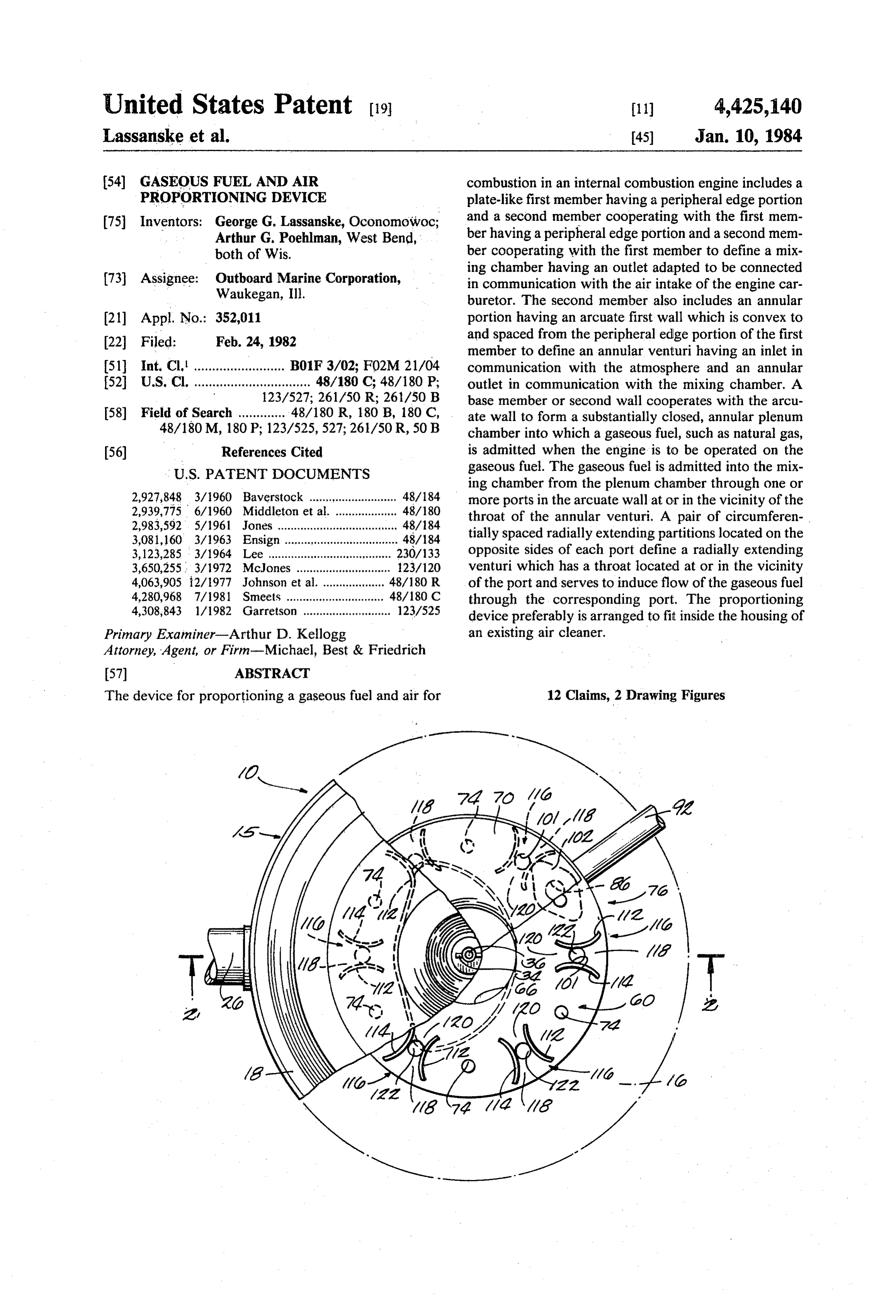
United States Patent (19) 11 4,425,140 Lassanske et al. 45) Jan. 10, 1984 (54) GASEOUS FUEL AND AIR combustion in an internal combustion engine includes a PROPORTIONING DEVICE plate-like first member having a peripheral edge portion (75) Inventors: George G. Lassanske, Oconomowoc, and a second member cooperating with the first mem Arthur G. Poehlman, West Bend, ber having a peripheral edge portion and a second mem both of Wis. ber cooperating with the first member to define a mix ing chamber having an outlet adapted to be connected (73) Assignee: Outboard Marine Corporation, in communication with the air intake of the engine car Waukegan, Ill. buretor. The second member also includes an annular (21) Appl. No. 352,011 portion having an arcuate first wall which is convex to 22 Filed: Feb. 24, 1982 and spaced from the peripheral edge portion of the first member to define an annular venturi having an inlet in 51 Int. Cl. ......................... B01F 3/02; F02M 21/04 communication with the atmosphere and an annular 52 U.S. Cl. ................................ 48/180 C; 48/180 P; outlet in communication with the mixing chamber. A 123/527; 261/50 R; 261/50 B base member or second wall cooperates with the arcu 58) Field of Search ............. 48/180 R, 180 B, 180 C, ate wall to form a substantially closed, annular plenum 48/180M, 180 P; 123/525,527; 261/50R, 50 B chamber into which a gaseous fuel, such as natural gas, 56) References Cited is admitted when the engine is to be operated on the
ing chamber from the plenum chamber through one or 2,927,848 3/1960 Baverstock ........... ... 48/184 more ports in the arcuate wall at or in the vicinity of the 2,939,775 6/1960 Middleton et al. . 48/180 throat of the annular venturi. A pair of circumferen 2,983,592 5/1961 Jones ..................................... 48/184 tially spaced radially extending partitions located on the 3,081,160 3/1963 Ensign.................................. 48/84 3,123,285 3/1964 Lee ........ ... 230/133 opposite sides of each port define a radially extending 3,650,255 3/1972 McJones ....... ... 23/120 venturi which has a throat located at or in the vicinity 4,063,905 i2/1977 Johnson et al. ... 48/180 R of the port and serves to induce flow of the gaseous fuel 4,280,968 7/1981 Smeets .......... 48/180 C through the corresponding port. The proportioning 4,308,843 1/1982 Garretson ........................... 123/525 device preferably is arranged to fit inside the housing of Primary Examiner-Arthur D. Kellogg an existing air cleaner. S. Attorney, Agent, or Firm-Michael, Best & Friedrich
The device for proportioning a gaseous fuel and air for 12 Claims, 2 Drawing Figures
Page 2
Drawing sheet — no readable text.
Page 3
ous fuel and air for combustion in an internal combus
GASEOUS FUEL AND AIR PROPORTIONING tion engine, which device can be mounted inside the
housing of an existing air cleaner to provide the engine with the capability of being operated on either a liquid
BACKGROUND OF THE INVENTION 5 fuel or a gaseous fuel.
This invention relates to devices for proportioning a Another of the principal features of the invention is gaseous fuel and air for combustion in an internal com the provision of such a proportioning device which bustion engine. In one aspect, the invention relates to does not require means for increasing the air flow area such devices which can be mounted on the air intake of when operation of the engine is switched from a gase the existing carburetor of an internal combustion engine O ous fuel to a liquid fuel.
to provide the engine with the capability of being oper Other features, aspects and advantages of the inven ated on either a liquid fuel or a gaseous fuel. tion will become apparent to those skilled in the art Systems for providing internal combustion engines upon reviewing the following detailed description, the with the capability of operating on either liquid fuel, 15 drawing and the appended claims.
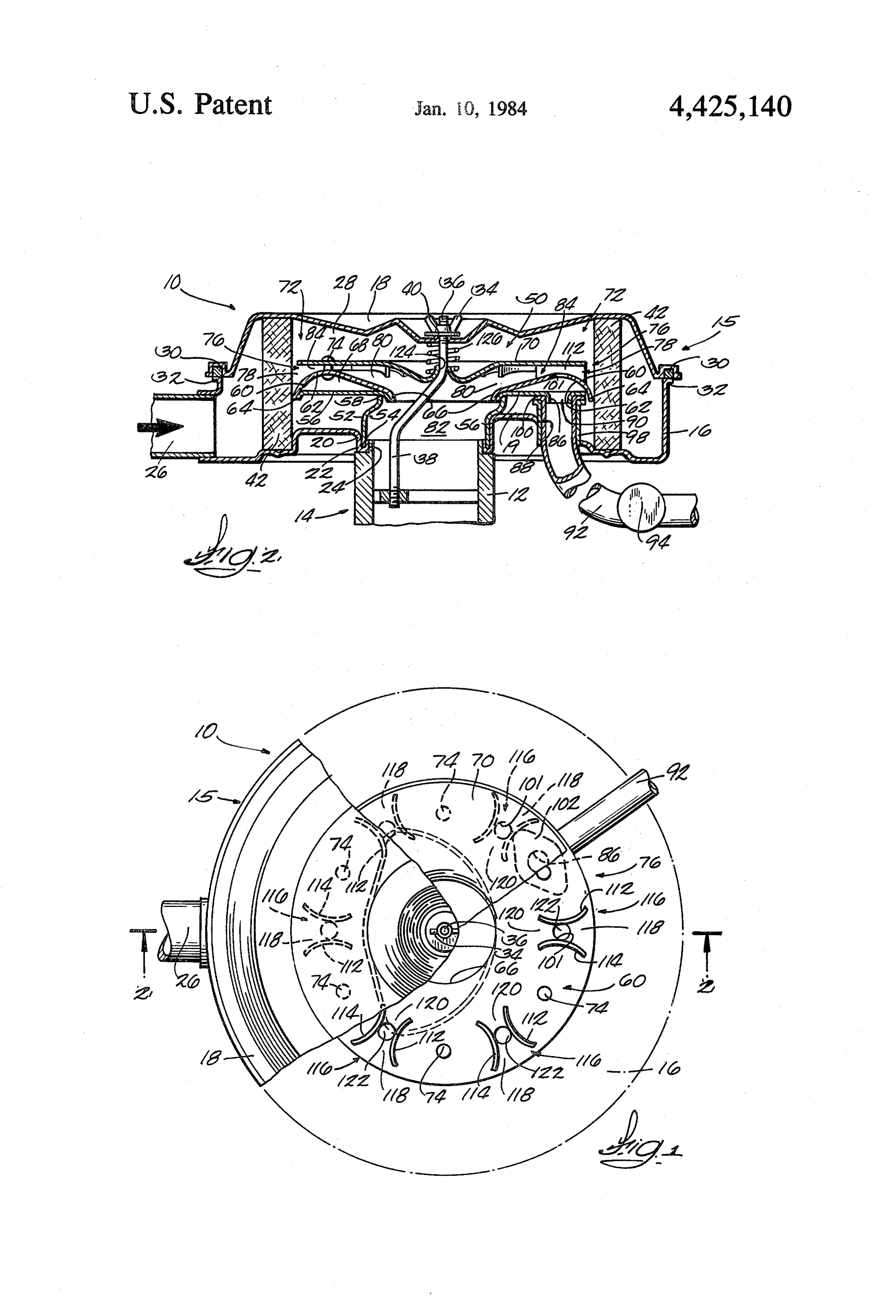
such as gasoline, or a gaseous fuel, such as natural gas, BRIEF DESCRIPTION OF THE DRAWING typically include a so-called gas mixer which fits onto the air intake of the existing carburetor and proportions FIG. 1 is a top view, partially broken, of a propor the tion.
gaseous fuel and air in the proper ratio. for combus tioning device which embodies various of the features
of the invention and which is shown mounted inside the housing of an existing air cleaner mounted on the air
Attention is directed to the following United States Patents: intake
Patentee U.S. Pat. No, Issue Date of an internal combustion engine carburetor.
FIG. 2 is a sectional view taken generally along line
Baverstock 2,927,848 March 8, 1960 2-2 in FIG. 1.
Jones' 2,983,592 May 9, 1961 25 Before explaining at least one of the embodiments of 3. Ensign 3,081,160 March 12, 1963 the invention in detail, it is to be understood that the ...'. Lee 3,123,285 March 3, 1964 invention is not limited in its application to the details of McJones
Johnson et, al.
construction and the arrangement of components set
Smeets 4,280,968 July 28, 1981 forth in the following description or illustrated in the drawings. The invention is capable of other embodi
Attention is also directed to application Ser. No. ways. ments and of being practiced and carried out in various 314,266, filed Oct. 23, 1981 and assigned to the assignee and terminology Also, it is to be understood that the phraseology of the present application. employed herein is for the purpose of description and should not be regarded as limiting.
SUMMARY OF THE INVENTION 35 DESCRIPTION OF THE PREFERRED
The invention provides a device for proportioning a EMBODIMENT gaseous fuel and air for an internal combustion engine, which device includes a wall means defining a mixing onIllustrated in the drawing is an air cleaner 10 mounted the air intake 12 of a conventional carburetor 14 chamber having an outlet adapted to be connected in communication with the internal combustion engine. (illustrated fragmentarily in FIG. 2) of a conventional The wall means also defines an annular venturi having internal combustion engine. Externally, the air cleaner an annular inlet in communication with the atmosphere, 10 is of conventional construction and includes a hous an annular outlet in communication with the mixing ing 15 including a bowl-like bottom section 16 and a chamber and an intermediate annular throat of reduced removable top section or cover 18. The bottom section cross sectional areas and further defines a substantially 45 6 includes a bottom wall 19 and a generally central closed, annular plenum chamber. The device includes sleeve portion 20 terminating in an upturned lip 22 means for selectively admitting a gaseous fuel into the which defines an aperture 24 for receiving the carbure plenum chamber, one or more ports communicating tor air intake 12. The air cleaner 10 includes an air inlet between the mixing chamber and the plenum chamber, duct 26 through which atmospheric air is admitted into and means disposed in the annular venturi defining a 50 an interior chamber 28 defined by the bottom section 16 radially extending venturi having an inlet in communi and the cover 18.
cation with the atmosphere, an outlet in communication The cover 18 carries an annular seal or gasket 30 with the mixing chamber and an intermediate throat at which seats on a peripheral flange 32 on the bottom or on the vicinity of the port, whereby air flowing section 16. The cover 18 is removably held in place by through the radial venturi induces flow of the gaseous 55 a wing nut 34 threaded onto the outer end 36 of an fuel through the port. attachment rod 38 extending through a central aperture In one embodiment, the radial venturi is formed by a 40 in the cover 18. The other end of the attachment rod pair of circumferentially spaced, radially extending 38 is connected to the carburetor 14 in the usual man partitions located on the opposite sides of a port and ner. Located inside the chamber 28 is a conventional extending between the peripheral edge portion of the 60 filter element 42 through which the air flows enroute first member and the arcuate wall of the second mem from the inlet duct 26 to the carburetor intake 12. ber. The partitions converge and then diverge in the Disposed inside the chamber 28 is a proportioning direction of airflow to form the radial venturi throat. device, designated generally by reference numeral 50, In a preferred embodiment, the mixing device is for mixing air and a gaseous fuel, such as natural gas, adapted to fit inside the housing of an existing air 65 The proportioning device 50 includes an annular sleeve cleaner. - ". . . . . . . . . . 52 having a lower end 54 which rests in the lip 22 on the One of the principal features of the invention is the bottom housing section 16, an annular base member 56 provision of a compact device for proportioning a gase connected to the upper end 58 of the sleeve 52, and an
Page 4
annular member 60 having an arcuate wall 62 and fur communication with the mixing chamber 82 and an ther having respective outer and inner peripheral edges intermediate, generally rectangular throat 122 in the 64 and 66 which are fastened to the base member 56 to area of minimum spacing between the partitions 112 and define a substantially closed annular plenum chamber 114 and between the arcuate wall 62 and the top 70. The 68. throat 122 of the radial venturi 116 is at or in the vicinity The proportioning device 50 also includes a plate or of the port 101.
disc-like member or top 70 which has an annular periph As air flows through the radial venturi 116, the fur eral edge portion 72 and which is mounted on the annu ther reduced pressure condition created in the vicinity lar member 60 in spaced relationship to the arcuate wall of the throat 122 induces greater flow of the gaseous 62 via a plurality of circumferentially spaced spacers 74. O fuel through the corresponding port 101 when the en The arcuate wall 62 is convex with respect to the pe gine is operating on a gaseous fuel.
ripheral edge portion 72 of the top 70 and cooperates When the engine is operating on a liquid fuel, such as therewith to form an annular venturi designated gener gasoline, the flow area for air to the carburetor intake 12 ally by reference number 76. The annular venturi 76 has is the total cross sectional area of the annular venturi an annular inlet 78 in communication with the atmo 15 throat 84 except for the relatively small space occupied sphere via the filter element 40 and the air inlet duct 26, by the partitions 112 and 114. an annular outlet 80 in communication with a mixing Thus, while the partitions 112 and 114 do not substan chamber 82 formed primarily by the top 70 and the tially decrease the total air flow area when the engine is sleeve 52, and an intermediate annular throat 84 in the operating on a liquid fuel, the radial venturis 116 formed area of minimum spacing between the arcuate wall 62 20 thereby do substantially increase the suction in the area and the top 70. immediately adjacent to the corresponding ports 101 to Means are provided for selectively admitting the more effectively draw the gaseous fuel into the mixing gaseous fuel into the plenum chamber 68. While various chamber 82 when the engine is operating on a gaseous means can be used, in the specific instruction illustrated, fuel. In other words, the radial venturis 116 serve as such means includes a circular opening 86 provided in 25 boost venturis. Accordingly, there is no need to provide the base member 56 and an opening 88 provided in the some mechanical means for increasing the flow area bottom wall 19 of the air cleaner section 16 and located when operation of the engine is switched from a gase coaxially with the base member opening 86. The base ous fuel to a liquid fuel as is the case with many prior member opening 86 is formed by a nipple 90. One end of constructions.
a pipe 92 is connected in communication with a source 30 The top 70 of the proportioning device 50 includes a of natural gas (not shown) through a suitable shutoff central aperture 124 through which the attachment rod valve 94 (illustrated schematically). The other end of 38 extends. A compression spring 126 disposed between the pipe 92 extends through a flexible grommet 98 the air cleaner cover 24 and the proportioning device mounted in the opening 88 in the air cleaner bottom top 70 maintains the lower end 54 of the sleeve 52 in wall 19 and fits over the nipple 90 on the base member 35 firm engagement with the air cleaner lip 22. 56. The pipe 92 terminates in a flare 100 and is held in By being arranged to fit inside the housing of an place by a clamp plate 102 which is suitably fastened to existing air cleaner, the proportioning device does not and clamps the hose flare 100 against the base member require any additional underhood space. Also, the exist 56. ing manifold heating system does not have to be re The gaseous fuel is admitted into the mixing chamber 40 moved or modified, so the warm-up characterisics of 82 from the plenum chamber 68 through one or more the engine when operating on gasoline are not affected. openings or ports 101 in the arcuate wall 62 at or in the Various of the features of the invention are set forth vicinity of the annular venturi throat 84. In the specific in the following claims:
instruction illustrated, a plurality (e.g., 6) of the ports We claim:
101 are provided in the arcuate wall 62 at substantially 45 1. A device for proportioning a gaseous fuel and air equal, circumferentially spaced intervals. for combustion in an internal combustion engine, said As air flows through the annular venturi 76 toward device including wall means defining a mixing chamber the mixing chamber 82, the reduced pressure condition having an outlet adapted to be connected in communi created in the vicinity of the annular venturi throat 84 cation with the internal combustion engine, said wall where the highest velocity exists tends to "suck' or 50 means also defining an annular venturi having an annu draw the gaseous fuel through the ports 101 when the lar inlet in communication with the atmosphere, an engine is operating on a gaseous fuel. To further reduce annular outlet in communication with said mixing the pressure in the vicinity of the ports 101 and thereby chamber, and an intermediate annular throat of reduced increase the suction, means defining a radially extending cross sectional area, said wall means further defining a venturi is provided in the annular venturi 76 in associa 55 substantially closed, annular plenum chamber, means tion with at least some of, and preferably all, the ports for selectively admitting a gaseous fuel into said plenum 101. chamber, a port communicating between said plenum More specifically, as best shown in FIG. 1, a pair of chamber and said annular throat, and partition means circumferentially spaced, radially extending walls or disposed in said annular venturi and defining a radially partitions 112 and 114 extend heightwise between the 60 extending venturi having an inlet in communication arcuate wall 62 and the top 70 and extend lengthwise with the atmosphere, an outlet in communication with radially inwardly from the outer edge of the top 70 to a said mixing chamber and an intermediate throat at or in point beyond the port 101. The partitions 112 and 114 the vicinity of said port, whereby air flowing through converge and then diverge in the direction of air flow to said radial venturi induces flow of the gaseous fuel form a radially extending venturi, generally designated 65 through said port.
116. The radial venturi 116 has a generally rectangular. 2. A device according to claim 1 including a plurality inlet 118 in communication with the atmosphere via the : of said ports which are circumferentially spaced at sub filter element 42, a generally rectangular outlet 120 in stantially equal intervals, and a plurality of said radially
Page 5
extending venturis respectively associated with said said radial venturi induces flow of the gaseous fuel plurality of ports. through said port.
3. A device according to claim 1 wherein said radial 7. A device according to claim 6 including a plurality venturi defining means comprises a pair of circumferen of said ports which are circumferentially spaced at sub tially spaced, radially extending partitions located on stantially equal intervals. the opposite side of said port, said partitions converging 8. A device according to claim 7 wherein said radial and then diverging in the direction of air flow to form venturi defining means comprises a pair of circumferen said radial venturi throat. tially spaced radially extending partitions located on the 4. A device according to claim 1 wherein said wall means includes a first member having a peripheral edge O opposite sides of each of said ports and extending be portion, a second member cooperating with said first and said firstperipheral tween said wall of edge portion of said first member said second member, said partitions member to define said mixing chamber and including an converging and then diverging in the direction of air annular portion having an arcuate first wall SE, is flow to form said radial venturi throat. convex to and spaced from said peripheral edge portion of said first chamber to define therebetween said annu 15 9. A device for proportioning a gaseous fuel and air lar venturi. for combustion in an internal combustion engine, said 5. A device according to claim 4 wherein said second device including wall means defining a mixing chamber member further includes a second wall cooperating cation with having an outlet adapted to be connected in communi with said first wall to define said plenum chamber. the internal combustion engine, said wall means also defining 6. A device for proportioning a gaseous fuel and air lar inlet in communication
for combustion in an internal combustion engine and annular with the atmosphere, an adapted to fit inside an existing air cleaner including a chamber,outlet in communication with said mixing and an intermediate annular throat of reduced housing having a hollow interior and a generally central cross sectional area, a port communicating with said opening adapted to receive the air intake of the engine annular throat and with a source of gaseous fuel, and carburetor, said device including a plate-like first mem 25 partition means disposed ber disposed in the hollow interior of the air cleaner defining a radially extending in said annular venturi and housing and having a peripheral edge portion, a second venturi having an inlet in member disposed in the hollow interior of the air communication with the atmosphere, an outlet in com cleaner housing and cooperating with said first member munication with said mixing chamber, and an interme to define a mixing chamber having an outlet in commu 30 diate throat at or in the vicinity of said port. nication with the carburetor air intake, said second 10. A device according to claim 9 including a plural member including an annular portion having an arcuate ity of said ports which are circumferentially spaced at first wall which is convex to and spaced from said pe substantially equal intervals, and a plurality of said radi ripheral edge portion of said first member to define ally extending venturis respectively associated with said therebetween an annular venturi having an annular inlet 35 pluarlity of said ports.
in communication with the atmosphere, an annular 11. A device according to claim 9 wherein said radial outlet in communication with said mixing chamber and venturi defining means comprises a pair of circumferen an annular throat of reduced cross section area interme tially spaced, radially extending partitions located on diate said annular venturi inlet and outlet, said second the opposite side of a said port, said partitions converg member further including a second wall cooperating 40 ing and then diverging in the direction of air flow to with said first wall to define a substantially closed, an form said radial venturi throat.
nular plenum chamber, means for selectively admitting 12. A device according to claim 9 wherein said wall a gaseous fuel into said plenum chamber, at least one means includes a first member having a peripheral edge port in said first wall for admitting the gaseous fuel from portion, a second member cooperating with said first said plenum chamber into said mixing chamber, and 45 member to define said mixing chamber and including an means disposed in said annular venturi defining a radi annular portion having an arcuate first wall which is ally extending venturi having an inlet in communication convex to and spaced from said peripheral edge portion with the atmosphere, an outlet in communication with of said first chamber to define therebetween said annu said mixing chamber and an intermediate throat at or in lar venturi.
the vicinity of said port, whereby air flklowing through 50 k k k k
Provenance
- Collection
- Cited prior art
- Original PDF
- patentimages.storage.googleapis.com →
- Filed
- 1982-02-24
- Pages
- 5
- Method
- pdftotext (the PDF's own text layer) + pdftoppm 300dpi page scans
- Source
- Google Patents bibliographic record
- Granted
- 1984-01-10
- Inventors
- George G. Lassanske; Arthur G. Poehlman; Outboard Marine Corp
- Transcribed from
- patentimages.storage.googleapis.com →