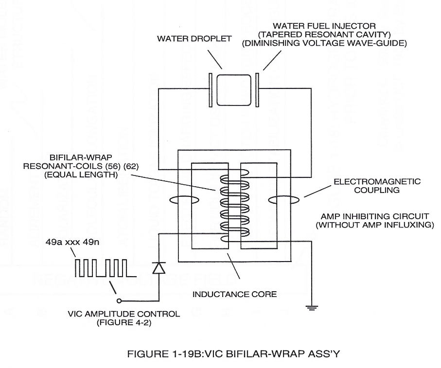
Figure (1-19B)
Figure (1-19B)
How it is written
- (1-19B) 4×
Drawings 1
-
Figure 1-19B · Amp Inhibiting Circuit Vs Voltage Enhancement
On this figure 5
- C Distributed Capacitance
- C2 Distributed Capacitance
- Cl Distributed Capacitance
- FL1 Distributed Inductance
- FL2 Distributed Inductance
Where it is named · 4
Amp Inhibiting Circuit Vs Voltage Enhancement 4×
-
Beyond amp restricting characteristic of said Amp Inhibiting Circuit of Figure (1-18) as to VIC Dual Single-coil Assembly (Figure 1-19A) and VIC Bifilar-Wrap Coil Assembly (Figure 1-19B), the spiral-wrapped coils being paired together, also, causes voltage level enhancement beyond applied voltage input since the "Distributed Capacitance" (Cl xxx Cln =C2a xxx C2n) / "Distributed Indu …
-
Figure 1-19B
-
Both VIC Dual Single-Coil (Figure 1-19A) and VIC Bifilar-Wrap Coil (Figure 1-19B) function similarly without incurring amp influxing. (See WFC U.S. Patent Validation Report titled "Natural Water Hydrogen Generation System filed September 16, 1981)
-
Figure 1-19B