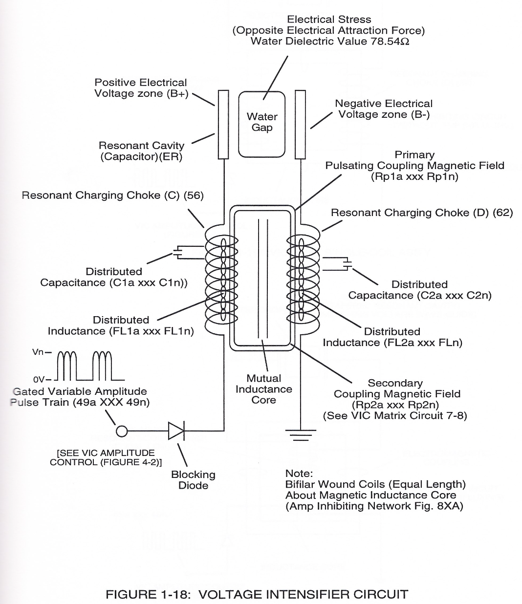
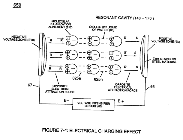
Figure (1-18)
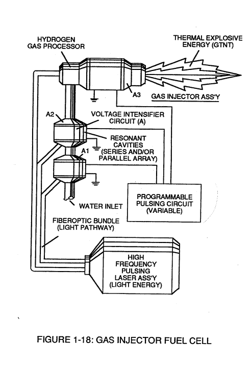
Gas Injector Fuel Cell
How it is written
- (1-18) 11×
Drawings 2
-
Captioned as this figure · Laser Interaction
-
(650) of Figure (7-4) · Amp Inhibiting Circuit Vs Voltage Enhancement
Where it is named · 11
Laser Interaction 1×
-
Injecting "Electromagnetically Primed" and "Electrically Charged" combustible gas ions (from water) into other light-activated Resonant Cavities further promotes gas-yield beyond voltage/laser stimulation, as illustrated in Figure (1-16) as to Figure (1-18).
Electron Extraction Process 4×
-
Exposing the displaced and moving combustible gas atoms (exiting waterbath and passing through Gas Resonant Cavity (T), Figure (1-17) as to Figure (1-18) to another or separate pulsating laser energy-source (V) at higher voltage levels (E3/E4) causes more electrons to be "pulled away" or "dislodged" from the gas atoms, as illustrated in Figure (1-15) as to Figure (1-8).
-
Figure (1-18)
-
Figure (1-18)
Thermal Explosive Energy 2×
-
Exposing the expelling "laser-primed" and "electrically charged" combustible gas ions (exiting from Gas Resonant Cavity) to a thermal-spark or heat-zone causes thermal gas-ignition, releasing thermal explosive energy (gmt) beyond the Gas-Flame Stage, as illustrated in Figure (1-19) as to (1-18).
-
Figure (1-18)
Rocket Propulsion 2×
-
Add-on Resonant Cavities (placed beneath the Hydrogen Gas Gun Assembly) arranged in parallel to vertical Cluster-Array increases the atomic Energy-Yield of the Hydrogen Fracturing Process undergoing thermal gas-ignition, as illustrated in Figure (1-22) as to Figure (1-18).
-
Figure (1-18)
Amp Inhibiting Circuit Vs Voltage Enhancement 2×
-
The resultant voltage enhancement (Voltage Amplitude) can exceed 40 kilovolts to instantly convert water (droplets) into thermal explosive energy (gtnt), as so illustrated in voltage Intensifier Circuit Diagram (Figure 1-18).