patent · US6371198B1
Heat storage device
16 April 2002
Page 1 — bibliographic record
(12) United States Patent (10) Patent No.: US 6,371,198 B1 Hirano (45) Date of Patent: Apr. 16, 2002
(54) HEAT STORAGE DEVICE 4,187,831. A 2/1980 Eubank ....................... 165/10
(75) Inventor: Satoshi Hirano, Tsukuba (JP) 5,687,706 A * 11/1997 Goswami et al. ........... 165/902 5,944,089 A 8/1999 Roland ........................ 165/10 (73) Assignee: Agency of Industrial Science and
Technology, Tokyo (JP) * cited by examiner (*) Notice: Subject to any disclaimer, the term of this Primary Examiner-Henry Bennett patent is extended or adjusted under 35 ASSistant Examiner Terrell McKinnon
U.S.C. 154(b) by 0 days. (74) Attorney, Agent, or Firm-Oblon, Spivak, McClelland, Maier & Neustadt, P.C.
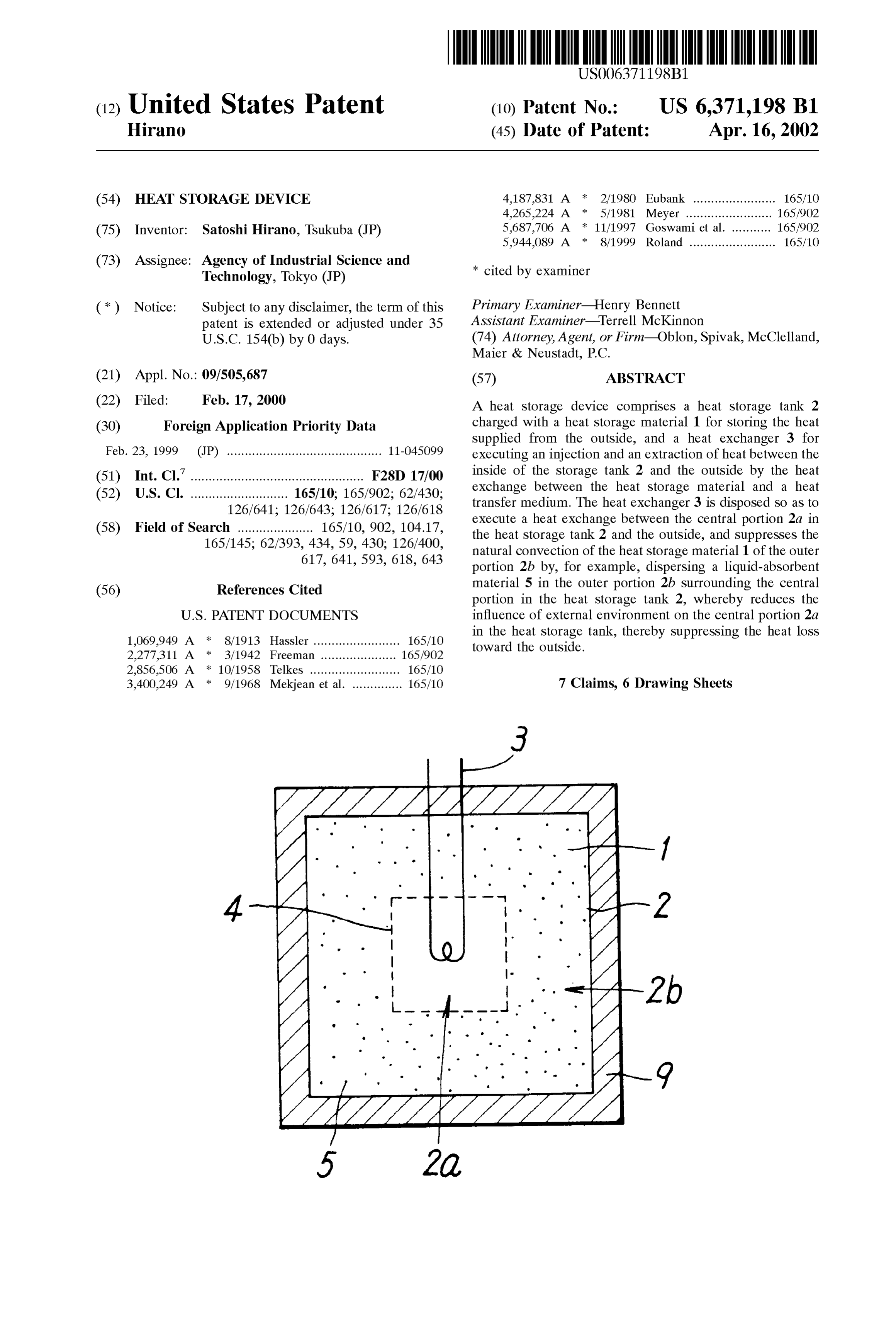
(21) Appl. No.: 09/505,687 (57) ABSTRACT (22) Filed: Feb. 17, 2000 A heat Storage device comprises a heat Storage tank 2 (30) Foreign Application Priority Data charged with a heat Storage material 1 for Storing the heat Supplied from the outside, and a heat eXchanger 3 for
Feb. 23, 1999 (JP) ........................................... 11-045099 executing an injection and an extraction of heat between the (51) Int. Cl. ................................................ F28D 17/00 inside of the Storage tank 2 and the outside by the heat (52) U.S. Cl. ........................... 165/10; 165/902; 62/430; eXchange between the heat Storage material and a heat 126/641; 126/643; 126/617; 126/618 transfer medium. The heat eXchanger 3 is disposed So as to (58) Field of Search ..................... 165/10, 902, 104.17, execute a heat eXchange between the central portion 2a in 165/145; 62/393, 434, 59, 430; 126/400, the heat Storage tank 2 and the outside, and Suppresses the 617, 641, 593, 618, 643 natural convection of the heat Storage material 1 of the outer portion 2b by, for example, dispersing a liquid-absorbent (56) References Cited material 5 in the outer portion 2b Surrounding the central portion in the heat Storage tank 2, whereby reduces the
1,069,949 A 8/1913 Hassler ........................ 165/10 in the heat Storage tank, thereby Suppressing the heat loSS toward the outside.
2.277.311 A * 3/1942 Freeman ..., ..., 165/902 2.856,506 A :* 10/1958 Telkes ......................... 165/10 3,400.249 A 9/1968 Mekjean et al. .............. 165/10 7 Claims, 6 Drawing Sheets
Page 2
Drawing sheet — no readable text.
Page 3
Drawing sheet — no readable text.
Page 4
Drawing sheet — no readable text.
Page 5
Drawing sheet — no readable text.
Page 6
Drawing sheet — no readable text.
Page 7
Drawing sheet — no readable text.
Page 8
HEAT STORAGE DEVICE transfer medium 47 in the processes of injection and extrac FIELD OF THE INVENTION tion will be opposite to each other. However, the basic operation is similar to the foregoing.
The present invention relates to a heat Storage device for On the other hand, in a heat storage device shown in FIG. temporarily Storing heat. 13, a heat Storage material 51 utilizing mainly transition heat DESCRIPTION OF THE RELATED ART is charged into Small vessels 56, which are accommodated in the heat Storage tank 52, and the heat Storage tank 52 is
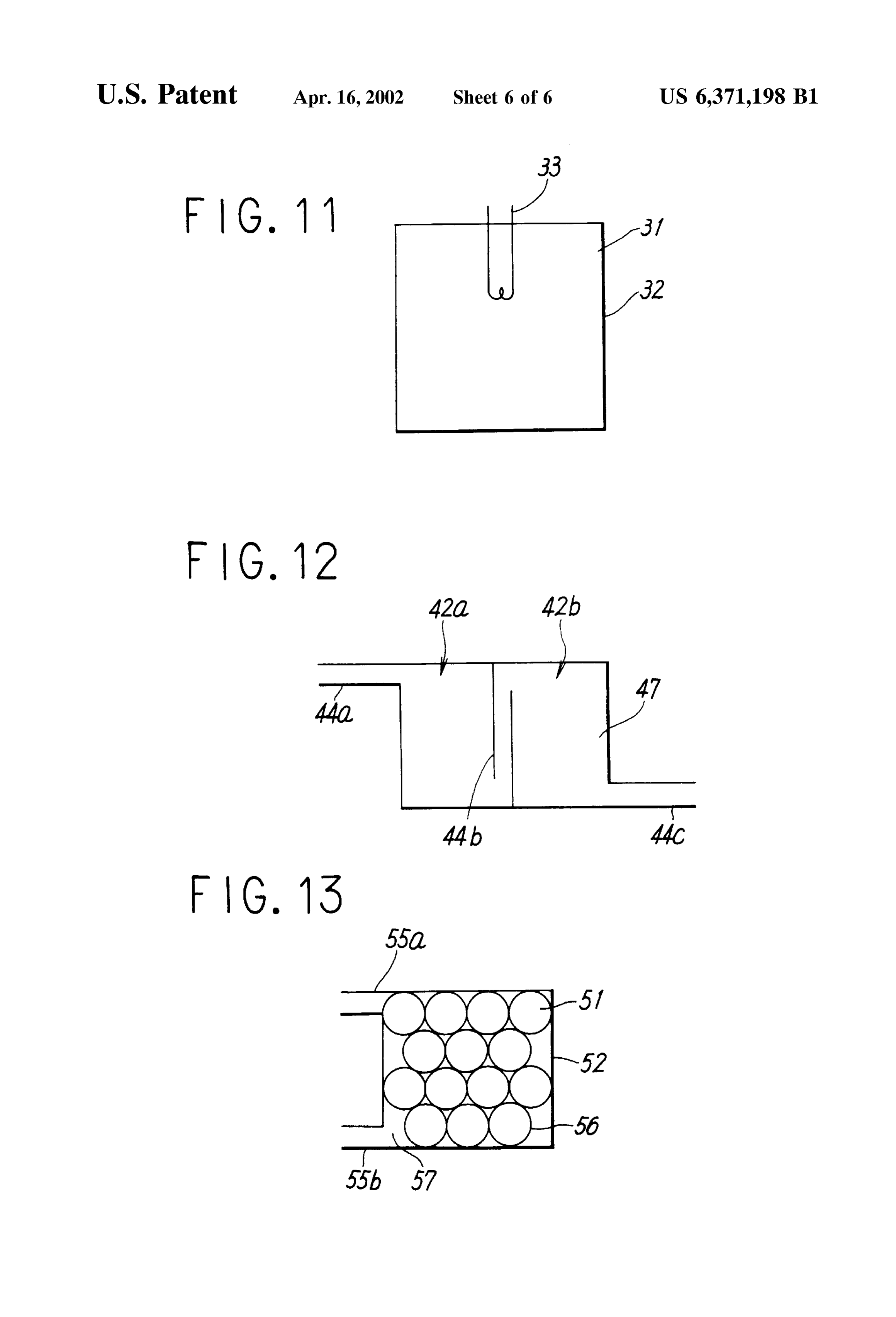
Basic constructions of conventional heat Storage devices provided with communicating tubes 55a and 55b for making are illustrated in FIGS. 11 through 13 in the form of sectional the heat Storage tank 52 communicate with the outside. By views. the heat transfer medium 57 which circulates through these A heat Storage device shown in FIG. 11 comprises a heat communicating tubes 55a and 55b and the heat storage tank, Storage tank 32 charged with a heat Storage material 31 Such heat eXchange means for executing a heat eXchange with the as water, and a heat eXchanger 33 disposed in the heat outside is constituted. In this case, the Storage of heat is Storage tank 32, for executing a heat eXchange with the mainly executed by the heat storage material 51 which outside. In order to Store the heat of, for example, a 15 utilizes a transition heat. Although the heat transfer medium temperature T within this heat Storage device, the tempera 57 functions as heat transport means, it does not mean that ture of the heat Storage material 31 is raised to T by adding the heat transfer medium 57 does not participate in the the heat of a temperature of at least T to the heat eXchanger Storage of heat.
33 from the outside. When heat is needed at the outside, the In this heat Storage device, in order to Store the heat of, for heat of the temperature T is extracted from the heat Storage example, a temperature T, the heat transfer medium 57 having a temperature of at least T is injected from the material 31 to the outside, using the heat eXchanger 33.
Aheat Storage device as shown in FIG. 12 comprises heat outside to the heat Storage tank 52 through the communi Storage tankS 42a and 42b charged with a heat transfer heat which 55a.
cating tube The heat storage material 51 is heated by the has been released by the heat transfer medium 57 medium 47 Such as water which also serves as a heat Storage via the walls of the Small vessels 56. The heat transfer material for Storing heat, wherein the heat Storage tank 42a 25 medium 57 injected returns to the outside passing through has a communicating tube 44a for connecting the heat the communicating tube 55b, and is again heated to a Storage tank 1 with the outside, wherein the heat Storage temperature of at lease T. Thus, a similar circulation is tankS 42a and 42b are connected by a communicating tube repeated. If heat is needed at the outside, a process in the 44b, and wherein the heat Storage tank 42b has a commu opposite direction to the process of heat injection is nicating tube 44c for connecting the heat Storage tank 42b executed. That is, the heat transfer medium 57 is injected with the outside. from the outside to the heat storage tank 52 through the In the operation of this heat Storage device, in order to communicating tube 55b. The heat transfer medium 57 Store the heat of, for example, a temperature T, the heat injected is heated by the heat released by the heat transfer transfer medium 47 is Sucked out from the communicating medium 51, via the walls of the Small vessels 56. The heat tube 44c, and the temperature of the heat transfer medium 47 35 transfer medium 57 heated returns to the outside passing is raised to at least T by adding heat to the heat transfer through the communicating tube 55a, and its temperature medium 47 at the outside, then the heat transfer medium 47 becomes lower than T as a result of the utilization at the being injected from the communicating tube 44a to the heat outside, then being injected again. Thus, a Similar circulation storage tanks 42a. The heat transfer medium 47 removed is repeated. Also in the case where the heat of a lower from the heat Storage tank 42a by this injection, arrives at the 40 temperature than the ambient temperature is Stored, the basic heat Storage tankS 42a passing through the communicating operation is similar to the foregoing.
tube 44a. After a while, the heat transfer medium 47 is In this example of constitution, Since the heat transfer Sucked out from the communicating tube 44c, and executes medium 57 which is injected and extracted from the outside a heat transport between the heat Storage tank 42 and the passes through the gaps between the Small vessels, the area outside, then returning to the heat Storage tank 42a again 45 of a heat transfer Surface to the heat Storage material 51 passing through the communicating tube 4.4a. Thus, a cir becomes large, as well as the treatment of the heat Storage culation of the heat transfer medium 47 is accomplished. If material 51 becomes easy, and hence Such a constitution is heat is needed at the outside, a proceSS in the opposite often used for heat Storage devices that use paraffin as a heat direction to the injection process of heat is executed. That is, Storage material 51 which utilizes transition heat. the heat transfer medium 47 is Sucked out from the com 50 municating tube 44a, and heat is absorbed and utilized at the FIGS. In the above-described heat Storage devices shown in 11 through 13, in the state of heat storage, if there are outside, and the heat transfer medium 47 of which tempera temperature differences between the heat Storage materials ture has decreased as a result of the absorption and utiliza 31, 51, and the heat transfer medium 47 which also serves tion of heat, is returned from the communicating tube 44c to as a heat Storage material, and the external environment the heat Storage tank 42b. Due to this returning, the heat 55 Surrounding the heat Storage tanks 32, 42, and 52, then heat transfer medium 47 removed from the heat storage tanks 42b transfer always takes place between the heat Storage devices flows into the heat Storage tank 42a passing through the and the external environment through the wall Surfaces of communicating tube 4.4b. Thus, a circulation of the heat heat Storage tanks 32, 42, and 52, respectively. transfer medium 47 is accomplished. Neglecting the influence of heat radiation which is usually An object of Suitably dividing the heat Storage tank is to 60 low, the heat loSS Q of a heat Storage material or a heat SuppreSS the occurrence of a dead water region where flow transfer medium which also serves as a heat Storage material is apt to Stagnate within the heat Storage tank, and to allow (hereinafter these are both referred to as a heat Storage the circulation of the heat transfer medium 47 in injecting material) is expressed by the following equation. and extracting heat to be uniformly conducted by using the whole of the heat Storage tank. 65
If the heat of a lower temperature than an ambient Here, k denotes an overall heat transfer coefficient deter temperature is stored, the directions of flow of the heat mined by the material, construction, and ambient air Speed
Page 9
of a heat Storage tank, etc. A denotes a contact area between Surface of the heat Storage material transfers, whereby heat a heat Storage tank and a ambient fluid (Such as air). To transfer always takes place between the heat Storage material represents an environmental temperature outside the heat and the external environment through the wall Surface of the Storage device, and T' represents a temperature at the heat Storage tank, and hence causes a large heat loSS within Surface where the heat Storage material contacts the heat the heat Storage material.
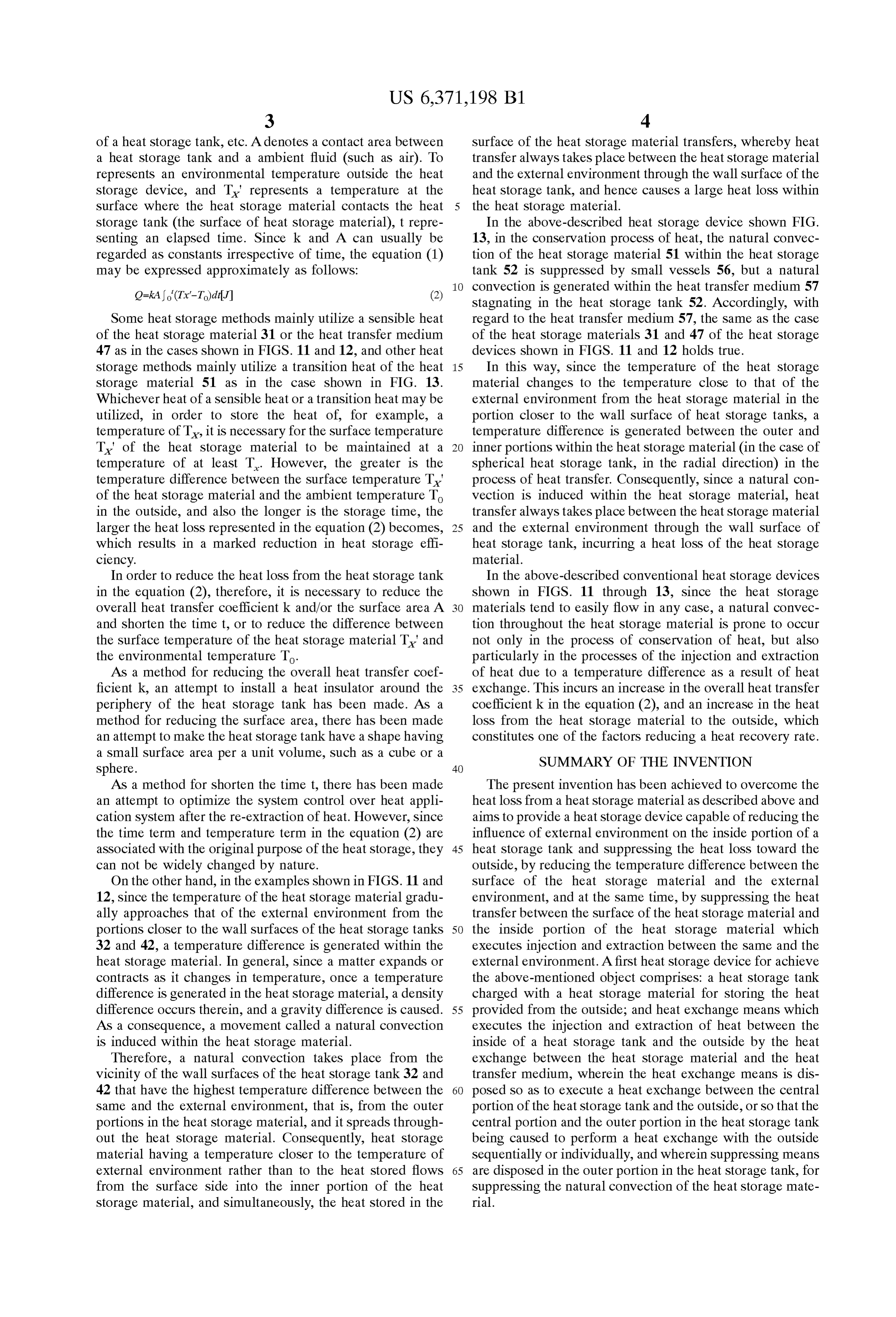
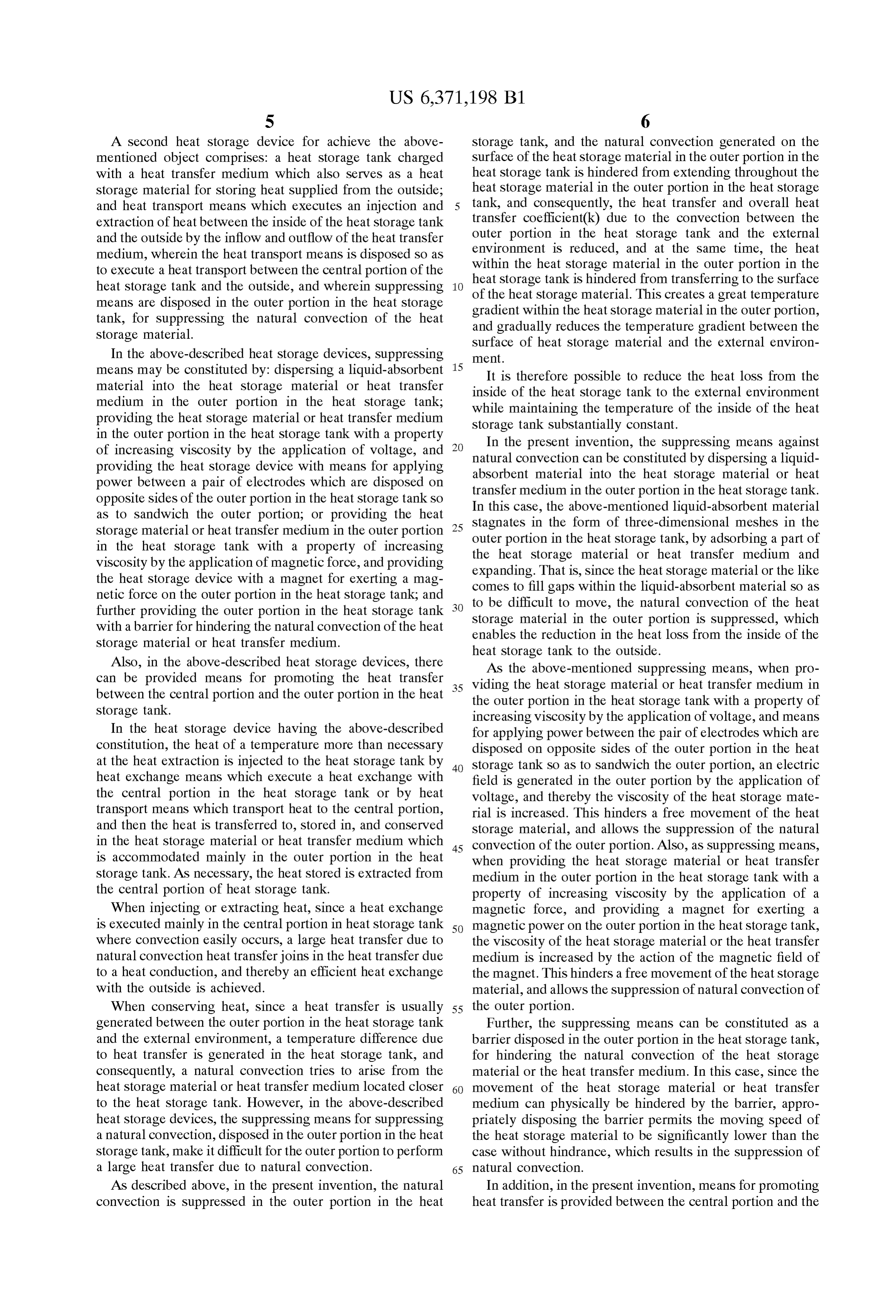
Storage tank (the Surface of heat storage material), t repre In the above-described heat storage device shown FIG. Senting an elapsed time. Since k and A can usually be 13, in the conservation process of heat, the natural convec regarded as constants irrespective of time, the equation (1) tion of the heat Storage material 51 within the heat Storage may be expressed approximately as follows: tank 52 is suppressed by small vessels 56, but a natural convection is generated within the heat transfer medium 57
Stagnating in the heat Storage tank 52. Accordingly, with
Some heat Storage methods mainly utilize a Sensible heat regard to the heat transfer medium 57, the same as the case of the heat Storage material 31 or the heat transfer medium of the heat storage materials 31 and 47 of the heat storage 47 as in the cases shown in FIGS. 11 and 12, and other heat devices shown in FIGS. 11 and 12 holds true. Storage methods mainly utilize a transition heat of the heat 15 In this way, Since the temperature of the heat Storage storage material 51 as in the case shown in FIG. 13. material changes to the temperature close to that of the Whichever heat of a sensible heat or a transition heat may be external environment from the heat Storage material in the utilized, in order to Store the heat of, for example, a portion closer to the wall Surface of heat Storage tanks, a temperature of T, it is necessary for the Surface temperature temperature difference is generated between the outer and T' of the heat Storage material to be maintained at a inner portions within the heat Storage material (in the case of temperature of at least T. However, the greater is the spherical heat Storage tank, in the radial direction) in the temperature difference between the Surface temperature T' process of heat transfer. Consequently, Since a natural con of the heat Storage material and the ambient temperature To vection is induced within the heat Storage material, heat in the outside, and also the longer is the Storage time, the transfer always takes place between the heat Storage material larger the heat loss represented in the equation (2) becomes, 25 and the external environment through the wall Surface of which results in a marked reduction in heat Storage effi heat Storage tank, incurring a heat loss of the heat Storage ciency. material.
In order to reduce the heat loSS from the heat Storage tank In the above-described conventional heat Storage devices in the equation (2), therefore, it is necessary to reduce the shown in FIGS. 11 through 13, since the heat storage overall heat transfer coefficient k and/or the Surface area A materials tend to easily flow in any case, a natural convec and shorten the time t, or to reduce the difference between tion throughout the heat Storage material is prone to occur the Surface temperature of the heat Storage material T' and not only in the process of conservation of heat, but also the environmental temperature To. particularly in the processes of the injection and extraction As a method for reducing the overall heat transfer coef of heat due to a temperature difference as a result of heat ficient k, an attempt to install a heat insulator around the 35 eXchange. This incurs an increase in the Overall heat transfer periphery of the heat Storage tank has been made. AS a coefficient k in the equation (2), and an increase in the heat method for reducing the Surface area, there has been made loSS from the heat Storage material to the outside, which an attempt to make the heat Storage tank have a shape having constitutes one of the factors reducing a heat recovery rate. a Small Surface area per a unit volume, Such as a cube or a SUMMARY OF THE INVENTION Sphere. 40
As a method for Shorten the time t, there has been made The present invention has been achieved to overcome the an attempt to optimize the System control over heat appli heat loSS from a heat Storage material as described above and cation System after the re-extraction of heat. However, Since aims to provide a heat Storage device capable of reducing the the time term and temperature term in the equation (2) are influence of external environment on the inside portion of a asSociated with the original purpose of the heat Storage, they 45 heat Storage tank and Suppressing the heat loSS toward the can not be widely changed by nature. outside, by reducing the temperature difference between the On the other hand, in the examples shown in FIGS. 11 and Surface of the heat Storage material and the external 12, Since the temperature of the heat Storage material gradu environment, and at the same time, by Suppressing the heat ally approaches that of the external environment from the transfer between the Surface of the heat Storage material and portions closer to the wall Surfaces of the heat Storage tanks 50 the inside portion of the heat Storage material which 32 and 42, a temperature difference is generated within the executes injection and extraction between the same and the heat Storage material. In general, Since a matter expands or external environment. A first heat Storage device for achieve contracts as it changes in temperature, once a temperature the above-mentioned object comprises: a heat Storage tank difference is generated in the heat Storage material, a density charged with a heat Storage material for Storing the heat difference occurs therein, and a gravity difference is caused. 55 provided from the outside; and heat eXchange means which AS a consequence, a movement called a natural convection executes the injection and extraction of heat between the is induced within the heat Storage material. inside of a heat Storage tank and the outside by the heat Therefore, a natural convection takes place from the eXchange between the heat Storage material and the heat vicinity of the wall Surfaces of the heat Storage tank 32 and transfer medium, wherein the heat eXchange means is dis 42 that have the highest temperature difference between the 60 posed So as to execute a heat eXchange between the central Same and the external environment, that is, from the outer portion of the heat Storage tank and the outside, or So that the portions in the heat Storage material, and it spreads through central portion and the outer portion in the heat Storage tank out the heat Storage material. Consequently, heat Storage being caused to perform a heat eXchange with the outside material having a temperature closer to the temperature of Sequentially or individually, and wherein Suppressing means external environment rather than to the heat stored flows 65 are disposed in the outer portion in the heat Storage tank, for from the surface side into the inner portion of the heat Suppressing the natural convection of the heat Storage mate Storage material, and Simultaneously, the heat Stored in the rial.
Page 10
S 6
A Second heat Storage device for achieve the above Storage tank, and the natural convection generated on the mentioned object comprises: a heat Storage tank charged Surface of the heat Storage material in the outer portion in the with a heat transfer medium which also serves as a heat heat Storage tank is hindered from extending throughout the Storage material for Storing heat Supplied from the outside; heat Storage material in the outer portion in the heat Storage and heat transport means which executes an injection and tank, and consequently, the heat transfer and overall heat extraction of heat between the inside of the heat Storage tank transfer coefficient(k) due to the convection between the and the outside by the inflow and outflow of the heat transfer outer portion in the heat Storage tank and the external environment is reduced, and at the same time, the heat medium, wherein the heat transport means is disposed So as within the heat Storage material in the Outer portion in the to execute a heat transport between the central portion of the heat Storage tank is hindered from transferring to the Surface heat Storage tank and the outside, and wherein Suppressing of the heat Storage means are disposed in the Outer portion in the heat Storage gradient within the material.heat
This creates a great temperature
Storage material in the outer portion, tank, for Suppressing the natural convection of the heat and gradually reduces the temperature gradient between the Storage material. Surface of heat Storage material and the external environ In the above-described heat Storage devices, Suppressing ment.
means may be constituted by: dispersing a liquid-absorbent 15 It is therefore possible to reduce the heat loss from the material into the heat Storage material or heat transfer inside of the heat Storage tank to the external environment medium in the Outer portion in the heat Storage tank; while maintaining the temperature of the inside of the heat providing the heat Storage material or heat transfer medium Storage tank Substantially constant.
in the Outer portion in the heat Storage tank with a property In the present invention, the Suppressing means against of increasing Viscosity by the application of Voltage, and natural convection can be constituted by dispersing a liquid providing the heat Storage device with means for applying absorbent material into the heat Storage material or heat power between a pair of electrodes which are disposed on transfer medium in the Outer portion in the heat Storage tank. opposite sides of the outer portion in the heat Storage tank So In this case, the above-mentioned liquid-absorbent material as to Sandwich the outer portion; or providing the heat Stagnates in the form of three-dimensional meshes in the
Storage material or heat transfer medium in the outer portion outer portion in the heat Storage tank, by adsorbing in the heat Storage tank with a property of increasing the heat Storage material or heat transfer medium a part of Viscosity by the application of magnetic force, and providing expanding. That is, Since the heat Storage material or the like and the heat Storage device with a magnet for exerting a mag comes to fill gaps within the liquid-absorbent material So as netic force on the Outer portion in the heat Storage tank, and to be difficult to move, the natural convection of the heat further providing the outer portion in the heat Storage tank Storage material in the outer portion is Suppressed, which with a barrier for hindering the natural convection of the heat enables the reduction in the heat loss from the inside of the Storage material or heat transfer medium. heat Storage tank to the outside. Also, in the above-described heat Storage devices, there AS the above-mentioned Suppressing means, when pro can be provided means for promoting the heat transfer 35 Viding the heat Storage material or heat transfer medium in between the central portion and the Outer portion in the heat the outer portion in the heat Storage tank with a property of Storage tank. increasing Viscosity by the application of Voltage, and means In the heat Storage device having the above-described for applying power between the pair of electrodes which are constitution, the heat of a temperature more than necessary disposed on opposite Sides of the outer portion in the heat at the heat extraction is injected to the heat Storage tank by 40 Storage tank So as to Sandwich the Outer portion, an electric heat eXchange means which execute a heat eXchange with field is generated in the outer portion by the application of the central portion in the heat Storage tank or by heat Voltage, and thereby the Viscosity of the heat Storage mate transport means which transport heat to the central portion, rial is increased. This hinders a free movement of the heat and then the heat is transferred to, Stored in, and conserved Storage material, and allows the Suppression of the natural in the heat Storage material or heat transfer medium which 45 convection of the outer portion. Also, as Suppressing means, is accommodated mainly in the outer portion in the heat when providing the heat Storage material or heat transfer Storage tank. AS necessary, the heat Stored is extracted from medium in the outer portion in the heat Storage tank with a the central portion of heat Storage tank. property of increasing Viscosity by the application of a When injecting or extracting heat, Since a heat eXchange magnetic force, and providing a magnet for exerting a is executed mainly in the central portion in heat Storage tank 50 magnetic power on the outer portion in the heat Storage tank, where convection easily occurs, a large heat transfer due to the Viscosity of the heat Storage material or the heat transfer natural convection heat transfer joins in the heat transfer due medium is increased by the action of the magnetic field of to a heat conduction, and thereby an efficient heat eXchange the magnet. This hinders a free movement of the heat Storage with the outside is achieved. material, and allows the Suppression of natural convection of When conserving heat, Since a heat transfer is usually 55 the outer portion.
generated between the outer portion in the heat Storage tank Further, the Suppressing means can be constituted as a and the external environment, a temperature difference due barrier disposed in the outer portion in the heat Storage tank, to heat transfer is generated in the heat Storage tank, and for hindering the natural convection of the heat Storage consequently, a natural convection tries to arise from the material or the heat transfer medium. In this case, Since the heat Storage material or heat transfer medium located closer 60 movement of the heat Storage material or heat transfer to the heat Storage tank. However, in the above-described medium can physically be hindered by the barrier, appro heat Storage devices, the Suppressing means for Suppressing priately disposing the barrier permits the moving Speed of a natural convection, disposed in the Outer portion in the heat the heat Storage material to be Significantly lower than the Storage tank, make it difficult for the outer portion to perform case without hindrance, which results in the Suppression of a large heat transfer due to natural convection. 65 natural convection.
AS described above, in the present invention, the natural In addition, in the present invention, means for promoting convection is Suppressed in the outer portion in the heat heat transfer is provided between the central portion and the
Page 11
outer portion in the heat Storage tank. When, for example, a or an extraction of heat between the central portion and the rapid injection to and an extraction from the heat Storage outer portion Sequentially, whereby it is possible to provide tank is required, it is possible to Speedily execute a heat a heat Storage device having a low heat loSS as described transfer between the central portion and the outer portion above while executing the exchange of heat between the where the heat transfer from the central portion is difficult heat Storage device and the outside rapidly and on a large due to the Suppression means against natural convection. Scale. Also, individually disposing heat eXchangers in the The heat eXchange means in the present invention can be central portion and the outer portion enables a Selective use disposed So that the central portion and the outer portion in of either the central portion or the Outer portion each having the heat Storage tank are caused to Sequentially perform a a different temperature, or both of them, whereby it becomes heat eXchange with the outside. By this constitution, when possible to provide a heat Storage device having a low heat injecting heat, by utilizing the residual heat remaining after loSS while efficiently executing an heat change between the the heating or cooling of the central portion in the heat heat Storage device and the outside in accordance with the Storage tank, it is possible to additionally heat or cool the Supply and demand of heat.
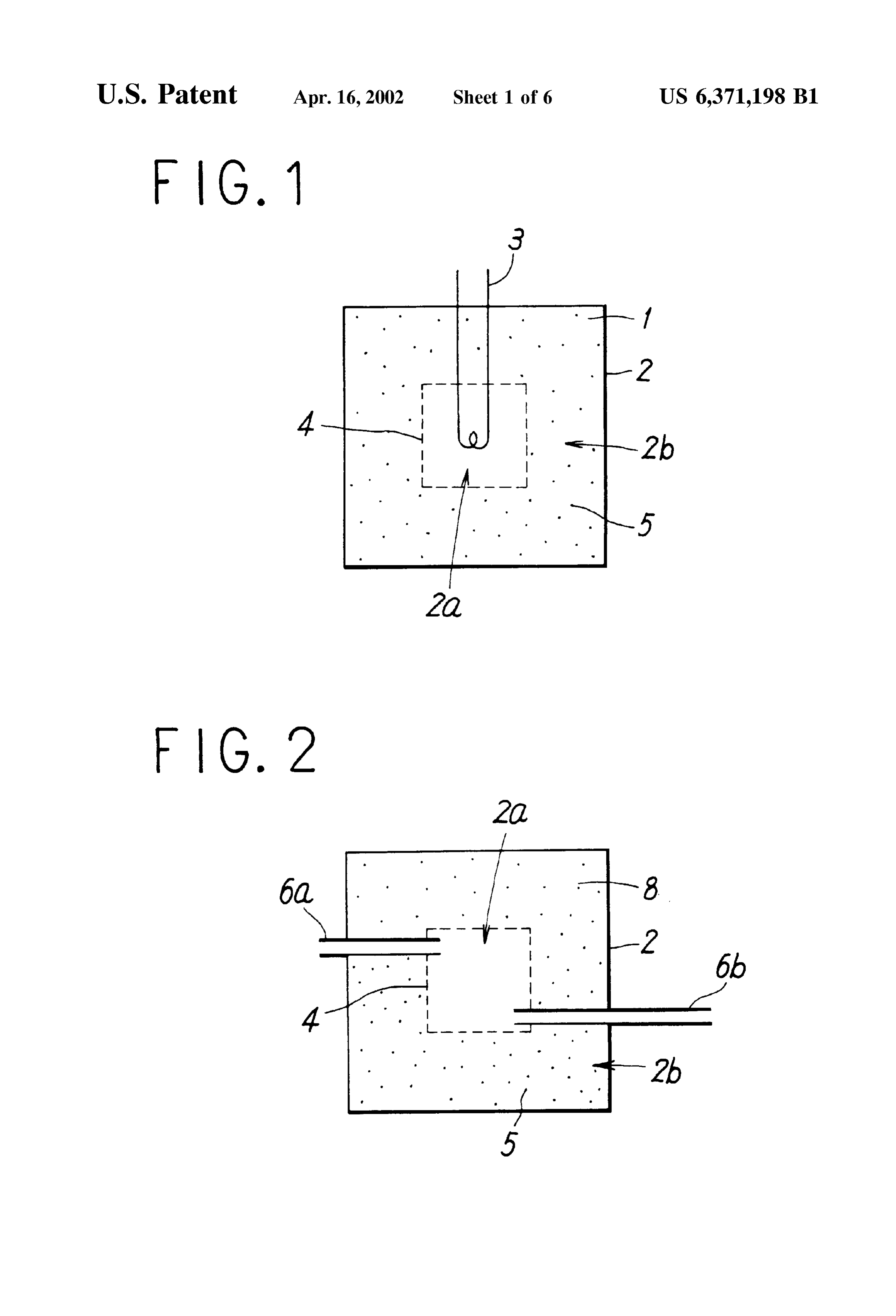
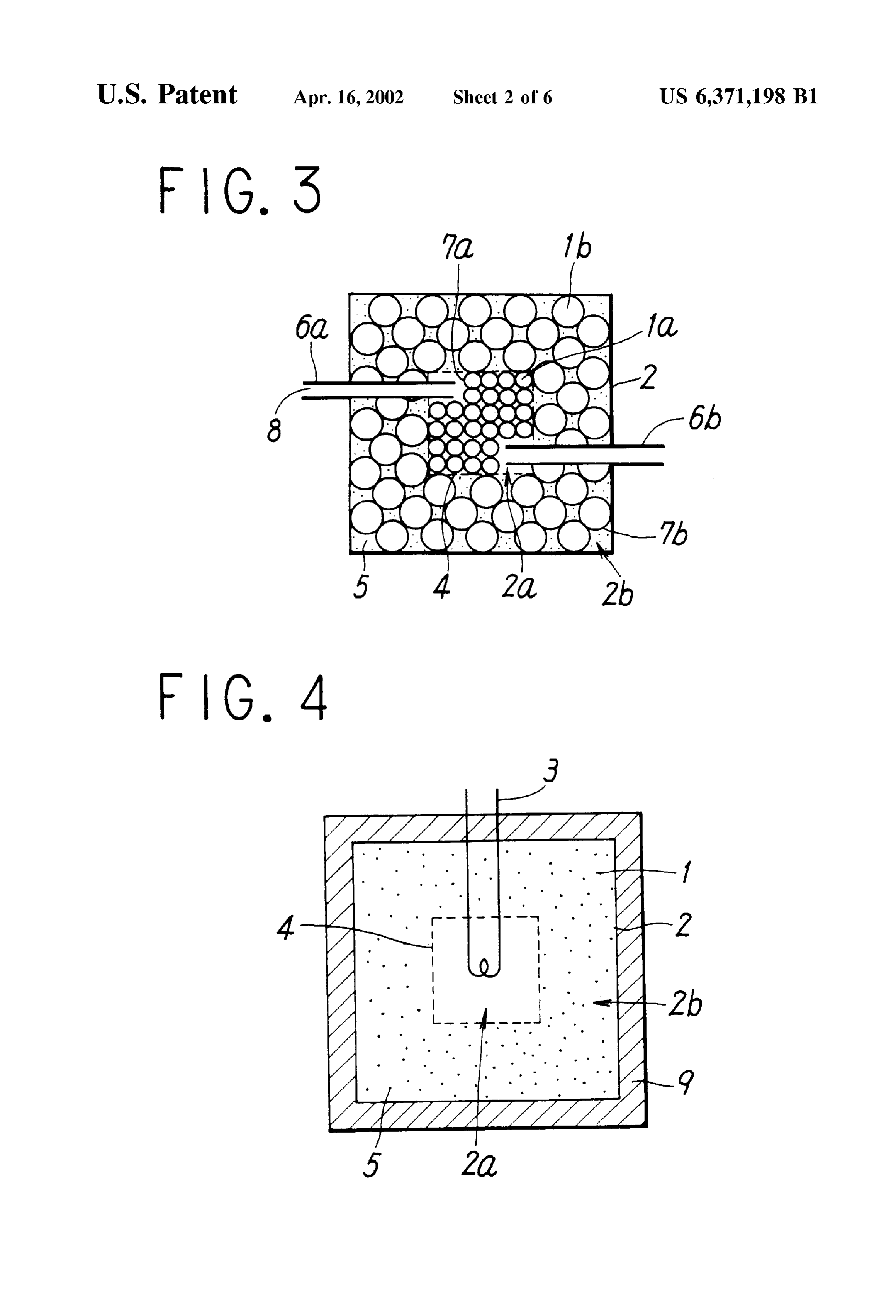
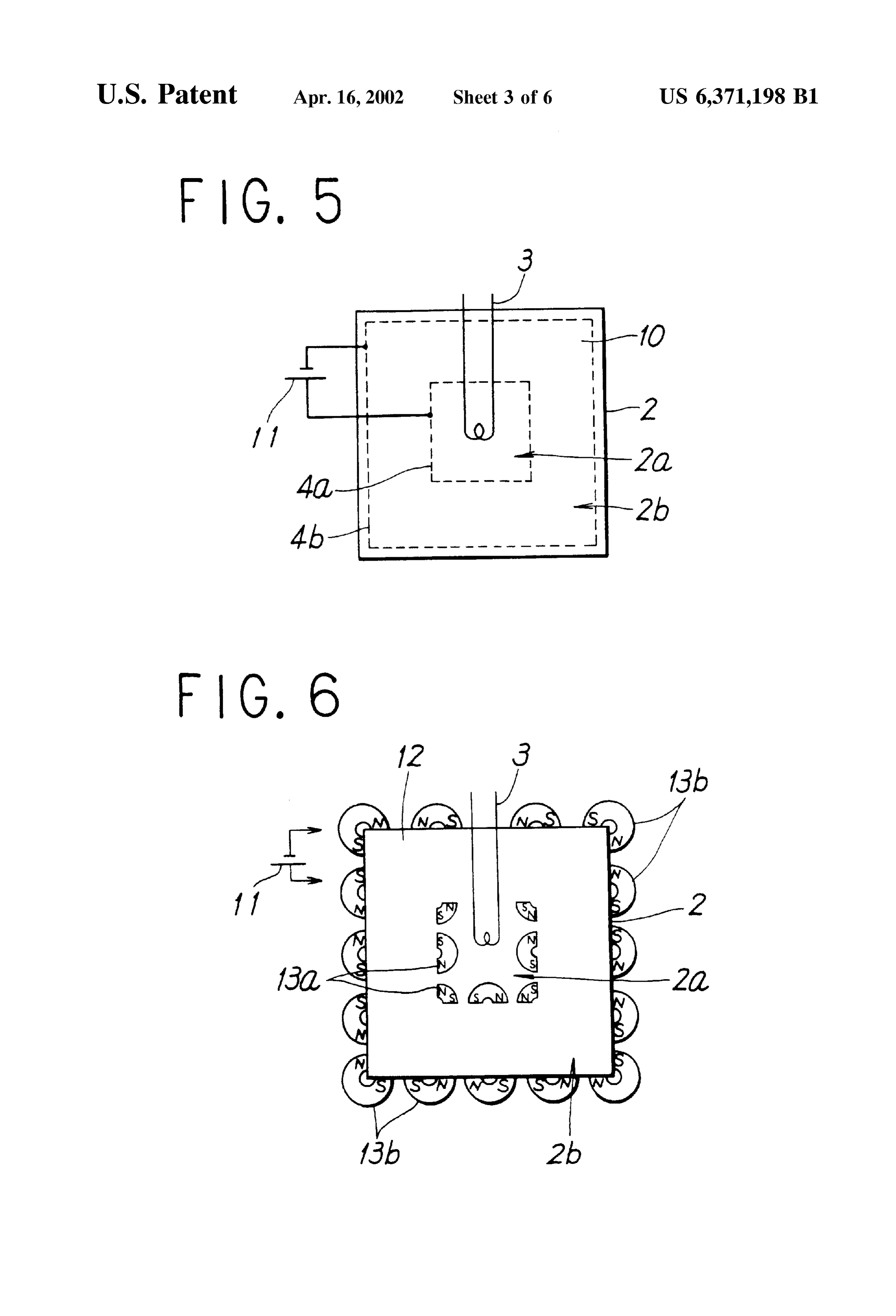
outer portion. On the contrary, when extracting heat, after BRIEF DESCRIPTION OF THE DRAWINGS the preheating or precooling of the heat eXchanger in the 15 outer portion in the heat Storage tank, it is possible to FIGS. 1 through 10 are sectional views showing varied additionally heat or cool the heat eXchanger in the outer embodiments of heat Storage devices of the present inven portion. This allows the exchange of heat between the heat tion.
Storage device and the external environment to be executed FIGS. 11 through 13 are sectional views showing varied rapidly and efficiently. examples of conventional heat Storage devices. Moreover, the heat eXchange means can be disposed So DETAILED DESCRIPTION OF THE that the central portion and the outer portion in the heat PREFERRED EMBODIMENTS Storage tank are caused to individually perform a heat eXchange with the outside. By this constitution, when inject 25 FIG. 1 is an1 embodiment of sectional view of the heat Embodiment ing heat, a heat eXchange can be executed in the central Storage device in accordance with the present invention. portion or the Outer portion whichever is more Suitable, in This heat Storage device accommodates a heat Storage accordance with the temperature of the heat injected from the outside to the heat Storage tank. On the contrary, when material 1 for Storing heat in a heat Storage tank 2 and has a heat eXchanger 3 in a heat Storage tank 2, as means for extracting heat, a heat eXchange may be executed in the executing a heat eXchange with the outside. As a heat Storage central portion or the outer portion whichever is more
Suitable, in accordance with the temperature of the heat material 1, Various materials may be used in accordance with required by the outside. Consequently, the exchange of heat a required heat Storage temperature. The heat Storage mate between the heat Storage device and the external environ rial 1 may be a material which makes a phase change in the processes of injection and extraction of heat. The inside ment can be executed rapidly and efficiently. 35 Space of the heat Storage tank is divided by a net 4 into a In accordance with the above-described heat Storage central portion 2a and an outer portion 2b Surrounding the devices associated with present invention, Since the ease of central portion 2. That is, within the heat Storage tank 2, the convection of the heat Storage material or heat transfer net 4 is stretched throughout the boundary between the medium within the heat Storage tank varies depending on central portion 2a and the outer portion 2b, and the central position, the injection operation from the outside to the heat 40 portion 2a is Surrounded by the Outer portion 2b via the net Storage material and the extraction operations from the heat 4. A liquid-absorbent material 5 is dispersed only in the heat Storage material to the outside are executed toward the Storage material 1 existing in the outer portion. central portion where a natural convection is easy to occur, It is preferable that the above-mentioned net 4 has a while the Storage of heat is executed in the central portion Stability toward the heat Storage material 1 and the liquid where a natural convection is difficult to occur. Therefore, in 45 absorbent material 5, and prevents the liquid-absorbent the processes of the injection and extraction of heat as well material 5 from mixing into the central portion 2a. as in the process of conservation, the natural convection The heat eXchanger 3 is provided as means for executing occurring within the inside of the heat Storage material due a heat eXchange between the outside of the heat Storage to the temperature difference from the outside takes place in device and the heat Storage material 1 existing in the central the central portion in the heat Storage tank and hardly takes 50 portion 2a, and its material and structure and the like are not place in the Outer portion, with the result that the overall heat limited as long as it is stable toward the heat Storage material transfer coefficient k becomes less than conventional cases. 1.
This enables the provision of a heat Storage device having a Preferably, the liquid-absorbent material 5 is stable low heat loss toward the outside. chemically and thermally toward the heat Storage tank 2 and Also, providing the central portion and the outer portion 55 the net 4, and increases the Viscosity of the heat Storage with heat transfer elements permits the heat transfer between material 1 existing in the Outer portion 2b, whereby it can the central portion and the outer portion where heat transfer constitute Suppressing means against natural convection. For does not much occur basically to be temporarily promoted, Such materials, various materials, for example, polymer whereby it is possible to provide a heat Storage device material particles with a high water-absorbency Such as having a low heat loSS as described above while executing 60 Starch-acrylonitrile graft polymeric hydrolysate, and fiber an efficient operating of the heat Storage tank in accordance Such as absorbent cotton are applicable. with the Supply and demand of heat. Next, a description is given of the operation of the heat Further, disposing heat eXchangerS So as to make a circuit Storage device shown in FIG. 1, for the case where a higher through the central portion and the outer portion in the heat temperature than that of environment outside the heat Stor Storage tank, permits the heat eXchanger to execute a direct 65 age device is Stored.
heat eXchange with the Outer portion where heat transfer In the injection process of heat, out of the heat Storage does not much occur basically, and to execute an injection material 1 charged into the heat Storage tank 2, the one
Page 12
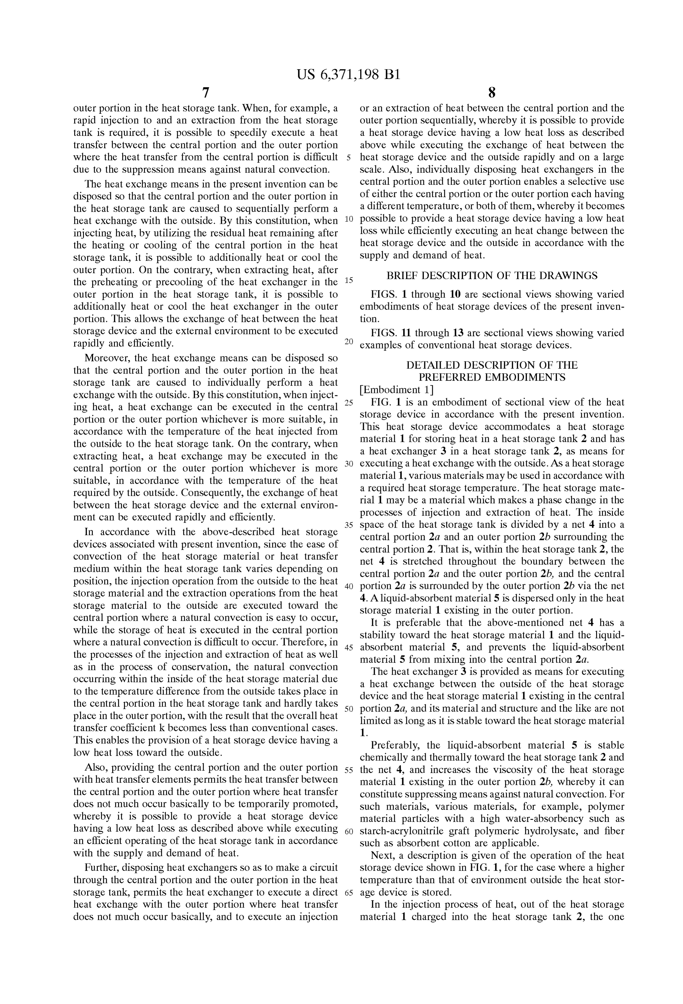
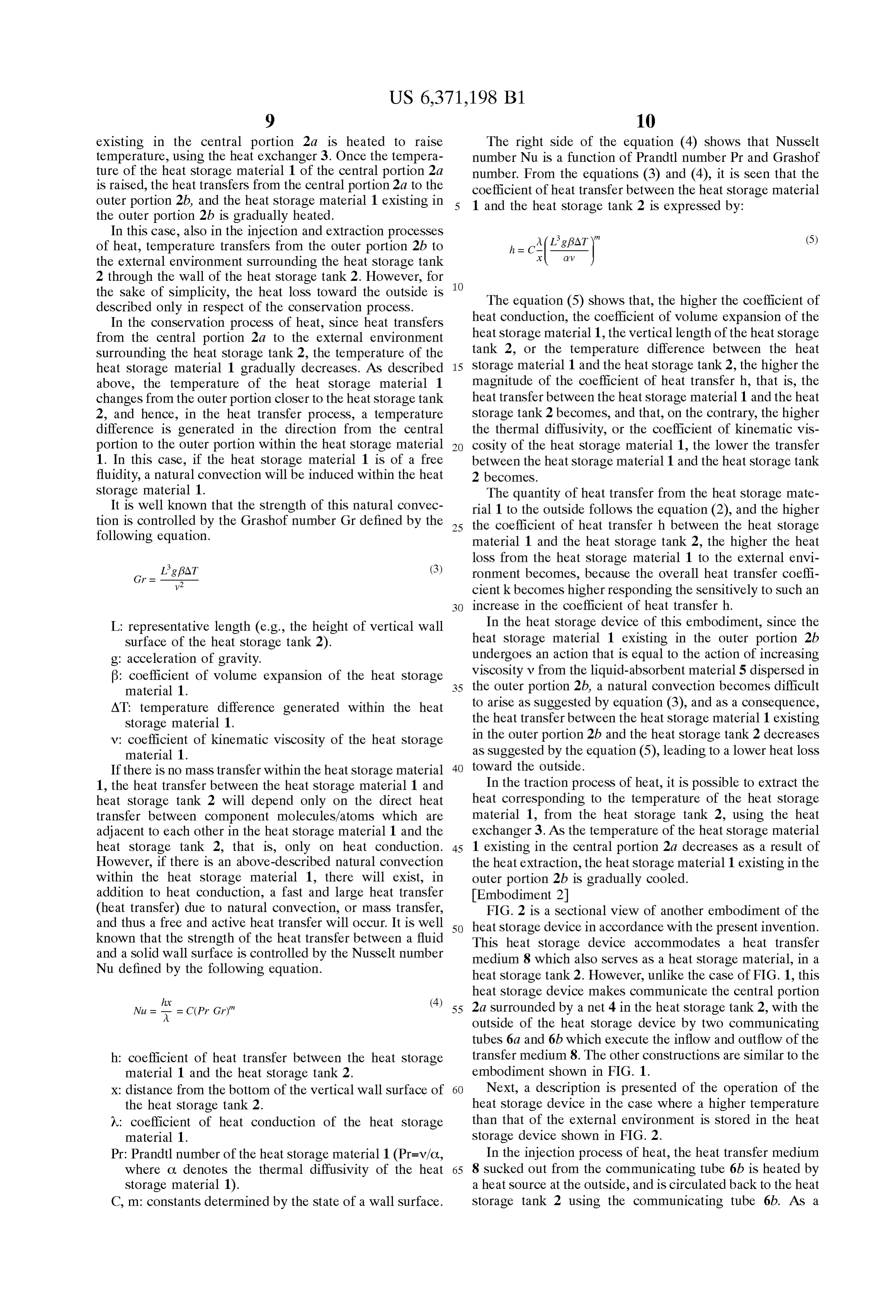
existing in the central portion 2a is heated to raise The right side of the equation (4) shows that Nusselt temperature, using the heat eXchanger 3. Once the tempera number Nu is a function of Prandtl number Pr and Grashof ture of the heat Storage material 1 of the central portion 2a number. From the equations (3) and (4), it is seen that the is raised, the heat transferS from the central portion 2a to the coefficient of heat transfer between the heat Storage material outer portion 2b, and the heat Storage material 1 existing in 1 and the heat Storage tank 2 is expressed by: the outer portion 2b is gradually heated.
In this case, also in the injection and extraction processes (5) of heat, temperature transferS from the Outer portion 2b to the external environment Surrounding the heat Storage tank 2 through the wall of the heat storage tank 2. However, for
the Sake of Simplicity, the heat loss toward the outside is The equation (5) shows that, the higher the coefficient of described only in respect of the conservation process.
In the conservation process of heat, Since heat transfers heat conduction, the coefficient of Volume expansion of the from the central portion 2a to the external environment heat Storage material 1, the vertical length of the heat Storage Surrounding the heat Storage tank 2, the temperature of the tank 2, or the temperature difference between the heat heat Storage material 1 gradually decreases. AS described 15 Storage material 1 and the heat Storage tank 2, the higher the above, the temperature of the heat Storage material 1 magnitude of the coefficient of heat transfer h, that is, the changes from the Outer portion closer to the heat Storage tank heat transfer between the heat Storage material 1 and the heat 2, and hence, in the heat transfer process, a temperature Storage tank 2 becomes, and that, on the contrary, the higher difference is generated in the direction from the central the thermal diffusivity, or the coefficient of kinematic vis portion to the outer portion within the heat Storage material cosity of the heat Storage material 1, the lower the transfer 1. In this case, if the heat Storage material 1 is of a free between the heat Storage material 1 and the heat Storage tank fluidity, a natural convection will be induced within the heat 2 becomes.
Storage material 1. The quantity of heat transfer from the heat Storage mate It is well known that the strength of this natural convec rial 1 to the outside follows the equation (2), and the higher tion is controlled by the Grashof number Gr defined by the 25 the coefficient of heat transfer h between the heat Storage following equation. material 1 and the heat Storage tank 2, the higher the heat loSS from the heat Storage material 1 to the external envi
Ligf8AT (3) ronment becomes, because the Overall heat transfer coeffi 2 cient k becomes higher responding the Sensitively to Such an increase in the coefficient of heat transfer h.
L. representative length (e.g., the height of vertical wall In the heat Storage device of this embodiment, Since the Surface of the heat Storage tank 2). heat Storage material 1 existing in the Outer portion 2b g: acceleration of gravity. undergoes an action that is equal to the action of increasing B: coefficient of Volume expansion of the heat Storage viscosity v from the liquid-absorbent material 5 dispersed in material 1. 35 the outer portion 2b, a natural convection becomes difficult AT: temperature difference generated within the heat to arise as Suggested by equation (3), and as a consequence, Storage material 1. the heat transfer between the heat Storage material 1 existing v: coefficient of kinematic Viscosity of the heat Storage in the Outer portion 2b and the heat Storage tank 2 decreases material 1. as Suggested by the equation (5), leading to a lower heat loss If there is no mass transfer within the heat Storage material 40 toward the outside.
1, the heat transfer between the heat Storage material 1 and In the traction process of heat, it is possible to extract the heat Storage tank 2 will depend only on the direct heat heat corresponding to the temperature of the heat Storage transfer between component molecules/atoms which are material 1, from the heat Storage tank 2, using the heat adjacent to each other in the heat Storage material 1 and the eXchanger 3. AS the temperature of the heat Storage material heat Storage tank 2, that is, only on heat conduction. 45 1 existing in the central portion 2a decreases as a result of However, if there is an above-described natural convection the heat extraction, the heat Storage material 1 existing in the within the heat Storage material 1, there will exist, in outer portion 2b is gradually cooled.
addition to heat conduction, a fast and large heat transfer Embodiment 2 (heat transfer) due to natural convection, or mass transfer, FIG. 2 is a sectional view of another embodiment of the and thus a free and active heat transfer will occur. It is well 50 heat Storage device in accordance with the present invention. known that the strength of the heat transfer between a fluid This heat Storage device accommodates a heat transfer and a solid wall surface is controlled by the Nusselt number medium 8 which also serves as a heat Storage material, in a Nu defined by the following equation. heat storage tank 2. However, unlike the case of FIG. 1, this heat Storage device makes communicate the central portion (4) 55 2a Surrounded by a net 4 in the heat Storage tank 2, with the
A. outside of the heat Storage device by two communicating tubes 6a and 6b which execute the inflow and outflow of the h: coefficient of heat transfer between the heat Storage transfer medium 8. The other constructions are similar to the material 1 and the heat Storage tank 2. embodiment shown in FIG. 1.
X: distance from the bottom of the vertical wall Surface of 60 Next, a description is presented of the operation of the the heat Storage tank 2. heat Storage device in the case where a higher temperature 2 : coefficient of heat conduction of the heat Storage than that of the external environment is stored in the heat material 1. storage device shown in FIG. 2.
Pr: Prandtl number of the heat storage material 1 (Pr=V/C, In the injection process of heat, the heat transfer medium where C. denotes the thermal diffusivity of the heat 65 8 Sucked out from the communicating tube 6b is heated by Storage material 1). a heat Source at the outside, and is circulated back to the heat C, m: constants determined by the State of a wall Surface. Storage tank 2 using the communicating tube 6b. AS a
Page 13
consequence, the temperature of the heat transfer medium 8 2, the temperature of the heat transfer medium 8 gradually existing in the central portion 2a rises, with the result that decreases. However, as in the case of the operation in FIG. heat is injected to the heat Storage tank2. AS the temperature 1, it becomes difficult for a natural convection to occur due of the heat transfer medium 8 in the central portion 2a rises, to the liquid-absorbent material 5 dispersed in the outer the heat transfer medium 8 in the outer portion 2b is portion 2b, and consequently, the heat transfer between the gradually heated. heat transfer medium 8 existing in the Outer portion 2b and In the conservation process of heat, Since heat transferS to the heat Storage tank 2 decreases, leading to a lower heat loSS toward the outside.
the external environment Surrounding the heat Storage tank The traction process of heat is Substantially the same as 2, the temperature of the heat transfer medium 8 gradually that of the embodiment shown in FIG. 2. decreases. However, as in the case of the operation in FIG. Embodiment 4 1, a natural convection becomes difficult to occur due to the FIG. 4 is a sectional view of another embodiment of the liquid-absorbent material 5 dispersed in the outer portion 2b, heat Storage device in accordance with the present invention. and consequently, the heat transfer between the heat transfer Although this heat Storage device has Substantially the same medium 8 existing in the outer portion 2b and the heat construction as that of the embodiment shown in FIG. 1, it Storage tank 2 decreases, leading to a lower heat loSS toward 15 has a thermal insulating layer 9 outside a heat Storage tank the outside. 2. Therefore, the description of the common parts with the In the traction process of heat, the heat transfer medium embodiment shown in FIG. 1 is omitted, and the common 8 accommodated in the heat Storage tank 2 is Sucked out referential numerals are marked with the identical numerals from the communicating tube 6a, and is utilized at the in FIG. 4.
outside as a heat Source having the temperature of the heat Next, a description is given of the operation of the heat transfer medium 8. The heat transfer medium 8 cooled as a Storage device in the case where a higher temperature than result of the thermal utilization is circulated back to the heat that of environment outside the heat Storage device is Stored Storage tank 2 through the communicating tube 6b. AS the in the heat storage device shown in FIG. 4. temperature of the heat transfer medium 8 existing in the The operation in the injection process of heat is basically central portion 2a decreases as a result of the heat extraction, 25 the same as that of the embodiment 1. the temperature of the heat transfer medium 8 existing in the Although the operation in the conservation process of heat outer portion 2b is gradually cooled. is also basically the same as that of the embodiment 1, the Embodiment 3 coefficient of heat conduction of the thermal insulating layer FIG. 3 is a sectional view of another embodiment of the 9 is lower than that of the heat storage tank 2, so that it is heat Storage device in accordance with the present invention. possible to reduce the overall heat transfer coefficient k In this heat Storage device, in a heat Storage tank 2 having shown in the equation (2) and to provide a heat Storage a similar construction as the embodiment shown in FIG. 2, device with a further lower heat loss. heat Storage materials 1a and 1b to be accommodated in the The operation in the extraction process of heat is basically central portion 2a and the Outer portion 2b are accommo the same as that of the embodiment 1.
dated in small vessels 7a and 7b, respectively. As heat 35 In this embodiment, a case is shown where the heat Storage materials 1a and 1b, various materials may be used Storage tank and the like is Same as those in the embodiment in accordance with required temperatures. The heat Storage 1, but these operations are applicable also for Such construc material may be a material which makes a phase change in tions as shown in the embodiment 2 or 3.
the processes of injection and extraction. Further, the heat Embodiment 5
Storage materials 1a and 1b which exist respectively in the 40 FIG. 5 is a sectional view of another embodiment of the central portion 2a and the outer portion 2b in a heat Storage heat Storage device in accordance with the present invention. tank 2 may be an identical material, or may be different Although this heat Storage device has a similar heat Storage materials. tank 2 and a heat eXchanger 3 to the embodiment shown in In the drawing, though small vessels 7a and 7b in this FIG. 1, it has an electrode 4a So as to Spatially Separate the embodiment are represented by a spherical shape, the mate 45 central portion 2a and the outer portion 2b, in place of the rial and shape of the Small vessel are not limited, as long as net 4 shown in FIG. 1. Also, an electrode 4b is stretched the Small vessels are stable toward the heat Storage materials around in the vicinity of the inner Surface of the heat Storage 1a and 1b and the heat transfer medium 8, and the dimen tank 2. The electrodes 4a and 4b are disposed on opposite sions of the small vessels may be different between those in Sides So as to Sandwich the outer portion 2b, each connected the central portion 2a and those in the Outer portion 2b, or 50 to a power Supply 11. Inside the heat Storage tank 2, an may be the Same. electrorheological fluid 10 is charged, which has a property Next, a description is given of the operation of the heat of increasing Viscosity by application of Voltage and which Storage device in the case where a higher temperature than Serves as a heat Storage material.
that of environment outside the heat Storage device is Stored The material and structure of the electrodes 4a and 4b are in the heat storage device shown in FIG. 3. 55 not limited, as long as they are capable of generating a In the injection process of heat, as in the case of the uniform electric field in the outer portion 2b by the appli embodiment shown in FIG. 2, the heat transfer medium 8 cation of Voltage to the power Supply 11. They may, for heated at the outside is circulated back to the heat Storage example, be reticular. Preferably, the electrorheological fluid tank, and consequently, heat transferS from the heat transfer 10 is stable toward the heat storage tank 2, the heat medium 8 to the heat Storage materials 1a, the temperature 60 eXchanger 3, the electrodes 4a and 4b. For an electrorheo thereof rising, thereby heat being injected to the heat Storage logical fluid, various materials Such as, for example, a liquid tank 2. AS the temperature of the heat Storage material 1 a which is Suspending carbon particles are applicable in existing in the central portion 2a rises, the heat Storage accordance with required heat Storage temperatures. material 8 existing in the outer portion 2b is gradually Next, an explanation is presented of the operation of the heated. 65 heat Storage device in the case where a higher temperature In the conservation process of heat, Since heat transferS to than that of the external environment is stored in the heat the external environment Surrounding the heat Storage tank storage device shown in FIG. 5.
Page 14
In the injection process of heat, out of the electrorheo The electromagnet 13a is disposed So that the magnetic logical fluid (heat storage material) 10 accommodated in the poles face away from the central portion 2a, and on the heat Storage tank 2, the one existing in the central portion 2a contrary, the electromagnet 13b is disposed So that the is heated to raise temperature, using the heat eXchanger 3, magnetic poles face away from the outside of the heat and thereby the electrorheological fluid 10 existing in the Storage device. The material and Structure of electromagnets outer portion 2b is gradually heated. 13a and 13b are not limited as long as they can generate a If the quantity of heat supplied from the outside to the heat magnetic field only in the Outer portion. For example, Storage device is lower than or equal to that of the quantity permanent magnets may be used in place of the electromag of heat diffusing from the central portion 2a to the outer nets 13a and 13b. Also in that case, the basic operation is the portion 2b, then a Voltage is applied between 4a and 4b by Same. For an electrorheological fluid 12, various materials, the power Supply 11. As a consequence, an electric field is Such as a liquid which is Suspending carbon particles, are generated between 4a and 4b, and the Viscosity of the applicable in accordance with required heat Storage tem electrorheological fluid 10 existing in the outer portion 2b peratures.
Sandwiched by the electrodes 4a and 4b is increased, result The processes of injection, conservation and extraction of ing in a lower heat loss toward the outside. 15 heat in the heat Storage device shown in FIG. 6 are the same If the quantity of heat supplied from the outside to the heat as those in the embodiment shown in FIG. 5, except that the Storage device is larger than the quantity of heat diffusing Viscosity of the magnetic fluid 12 is increased by the from the central portion 2a to the outer portion 2b, then it generation of the magnetic field through the energizing of will be possible to reduce the viscosity of the outer portion the electromagnets 13a and 13b in place of the generation of 2b by not applying a Voltage between the electrodes 4a and electric field.
4b, and to allow the heat transfer from the central portion 2a The operation in the case where the electromagnets 13a to the outer portion 2b to freely take place, thereby causing and 13b are replaced with permanent magnets is the same as the heat injected from the outside to be absorbed efficiently that of the case where the electromagnets 13a and 13b are into the heat Storage tank 2. energized. Further, as in the case of the embodiment 4, a heat In the conservation process of heat, a Voltage is applied to 25 Storage device with a lower heat loSS can also be achieved the electrodes 4a and 4b by the power Supply 11. The by covering the heat Storage tank with the thermal insulating application of a Voltage reduces the heat loSS from the heat layer 9.
Storage device to the outside for the foregoing reason. Embodiment 7
In the extraction process of heat, the heat corresponding FIG. 7 is a sectional view of another embodiment of the to the temperature of the electrorheological fluid 10 can be heat Storage device in accordance with the present invention. extracted from the heat Storage tank 2 through the heat This heat Storage device accommodates a heat Storage eXchanger 3. AS the temperature of the electrorheological material 1 for Storing heat, in a heat Storage tank 2 thereof, fluid 10 in the outer portion 2b decreases as a result of the and has a heat exchanger 3 for executing a heat exchange extraction of heat, the electrorheological fluid 10 in the with the outside, in the heat Storage tank 2, as in the case of central portion 2a gradually cooled. 35 the embodiment shown in FIG. 1. However, it has a multi
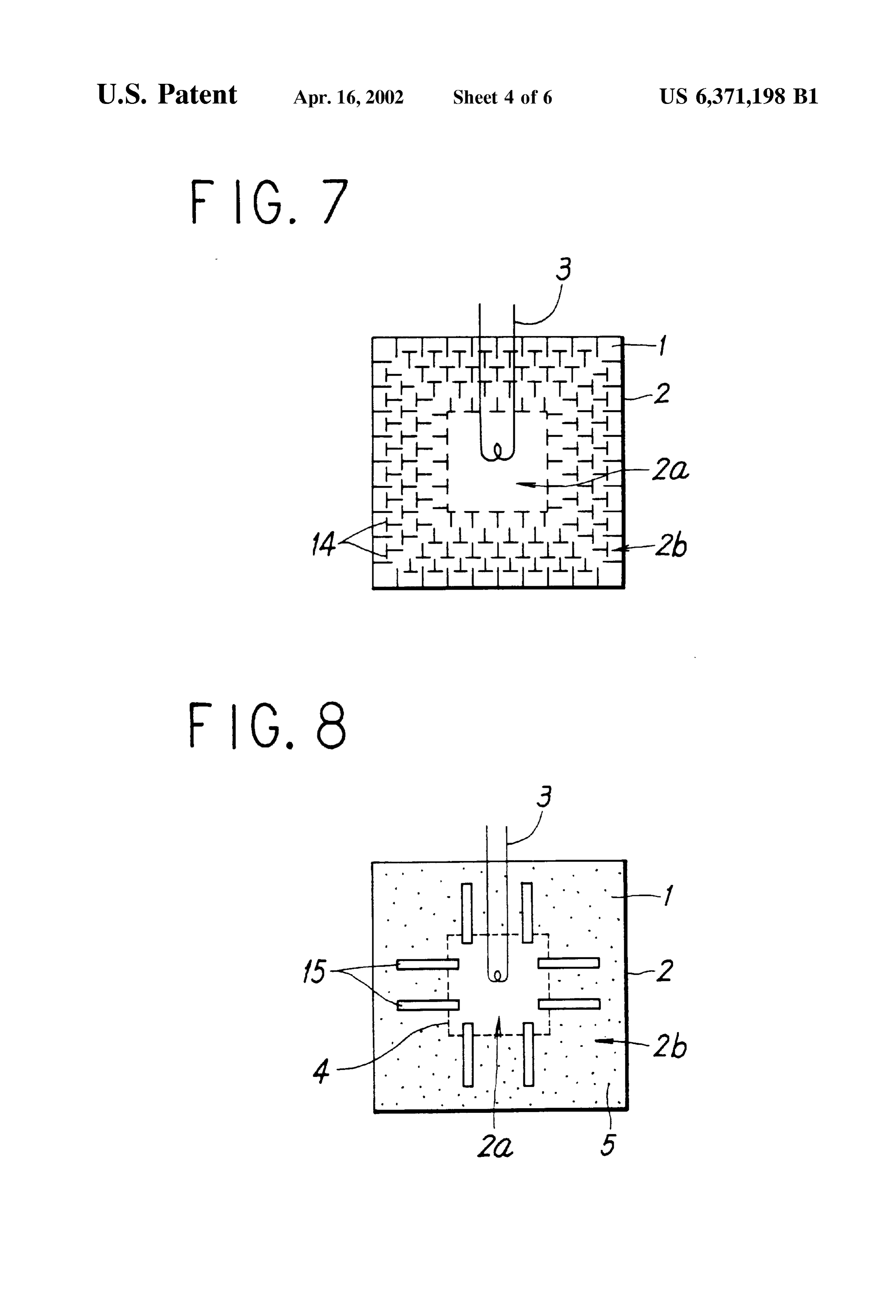
If the quantity of heat required of the heat Storage device tude of barriers 14 disposed in the outer portion 2b parti by the outside is met by the heat conserved in the central tioned by a net 4 in the a heat Storage tank 2. For the barriers portion 2a, a Voltage will be applied to the electrodes 4a and 14, for example, reticular ones may be applicable. 4b by the power Supply 11. The application of a Voltage reduces the heat loSS from the heat Storage device to the 40 theInembodiment this embodiment, a liquid-absorbent material 5 used in shown in FIG. 1 is not used, but it may be outside for the foregoing reason. If the quantity of heat employed. Because required of the heat Storage device by the outside is not met embodiment shown other constructions are the same as the in FIG. 1, description of them is omit by only the heat conserved in the central portion 2a, it will ted.
be possible to reduce the viscosity of the outer portion 2b by not applying a voltage between the electrodes 4a and 4b, and 45 Next, an explanation is presented of the operation of the to allow the heat transfer from the outer portion 2b to the heat Storage device in the case where a higher temperature central portion 2a to freely take place, thereby causing the than that of environment outside the heat Storage device is heat needed at the outside to be extracted efficiently from the stored in the heat storage device shown in FIG. 7. heat Storage tank 2. The operation in the injection process of heat is basically Further, as in the case of embodiment 4, a heat Storage 50 the same as that of the embodiment 1. In the conservation device having a lower heat loSS can be achieved by covering process of heat, Since heat transferS from the central portion the heat Storage tank with the thermal insulating layer 9. 2a to the external environment, the temperature of the heat Embodiment 6 Storage material 1 gradually decreases. However, even if the FIG. 6 is a sectional view of another embodiment of the heat Storage material 1 of the Outer portion 2b tries to heat Storage device in accordance with the present invention. 55 transfer to the central portion 2a, it will repeatedly collide This heat Storage device has a similar heat Storage tank 2 and against the minutely intricated barriers 14, So that the heat exchanger 3 to the embodiment shown in FIG. 1, but in moving Speed of the heat Storage material 1 becomes lower the heat Storage tank 2 a magnetic fluid 12 is charged, which than the case without the barriers 14, and thereby the heat has a property of increasing Viscosity by the application of Storage material 1 undergoes an action that is apparently a magnetic field. 60 equal to the action of increasing Viscosity v of the heat On the boundary between the central portion 2a and the Storage material 1 existing in the outer portion 2b, which outer portion 2b in the heat Storage tank 2, and outside the leads to a lower heat loSS toward the outside. heat Storage tank 2, a multitude of electromagnets 13a and The operation in the extraction process of heat is also 13.b which generate a magnetic force by a application of an basically the same as that of the embodiment 1. Further, as external power Supply, are disposed by an arbitrary number. 65 in the case of the embodiment 4, a heat Storage device In the drawing, the wiring between the electromagnets 13a having a lower heat loSS can be achieved by covering the and 13b and the power Supply 11 are omitted. heat Storage tank with the thermal insulating layer 9.
Page 15
Embodiment 8 the central portion 2a of the heat Storage material 1 charged FIG. 8 is a sectional view of another embodiment of the into heat Storage tank 2 is heated to increase temperature heat Storage device in accordance with the present invention. using the heat eXchanger 16. Next, the heat Storage material This heat Storage device has basically the same construction 1 of the outer portion 2b is heated by using the residual heat. as the embodiment shown in FIG. 1, and in the outer portion In the embodiment 1, the heat Storage material 1 of the outer 2b partitioned by a net 4 in a heat Storage tank 2, a portion 2b is gradually heated through the heat transfer due liquid-absorbent material 5 is dispersed in a heat Storage to the temperature increase of the heat Storage material 1 of material 1. Further, a heat transfer element 15 capable of the central portion 2a, but the outer portion 2b has a high arbitrarily promoting heat transfer is disposed between the apparent Viscosity as described in the embodiment 1, So that central portion 2a and the outer portion2b in the heat Storage a heat transfer is difficult to occur. By utilizing the heat tank. The heat transfer element 15 may be, for example, one eXchanger 16, a more rapid injection of heat than the case of capable of transporting any quantity of heat in any direction the embodiment 1 can be achieved.
by the application of Voltage, or may be one which markedly The conservation process of heat is similar to that of the varies in the heat transfer resistance with temperature, Such embodiment 1.
as a heat pipe. 15 In the extraction process of heat, by using the heat Next, an explanation is presented of the operation of the existing in the outer portion 2b out of the heat Storage heat Storage device in the case where a higher temperature material 1 charged into the heat Storage tank 2, the heat than that of the external environment is stored in the heat transfer medium to perform a heat eXchange with the outside storage device shown in FIG. 8. are heated by way of preheating. Next, the heat transfer The operation in the injection process of heat is basically medium is heated by the heat of the heat Storage material 1 the same as the case of the embodiment 1. However, if the of the central portion 2a. In this embodiment, as in the case quantity of heat Supplied by the outside is more than heats of the embodiment 1, the outer portion2b is high in apparent the heat Storage material 1 of the central portion 2a, it is viscosity so as to be difficult to perform heat transfer. possible, in addition to the procedure in the embodiment 1, However, use of the heat eXchanger enables a more rapid to promote the heat transfer from the central portion 2a to 25 injection of heat than the case of the embodiment 1. the outer portion 2b by the heat transfer element 15, and In this embodiment, a case where the heat Storage tank thereby store the heat supplied by the outside in the heat and the like are similar to those in the embodiment 1 is Storage device as completely and rapidly as possible. The shown, but Similar operations to the forgoing can be operation in the conservation process of heat is also similar achieved also when applied to Such structures as shown in to that of the embodiment 1, and the heat loss from the heat the embodiments 2 through 8.
Storage device is less than conventional cases. Embodiment 10
The operation in the extraction process of heat is also FIG. 10 is a sectional view of another embodiment of the basically the same as that of the embodiment 1. However, if heat Storage device in accordance With the present invention. the quantity of heat Supplied by the outside is not met by This heat storage device has heat exchangers 17a and 17b only the use of the heat Stored in the heat Storage material 1 35 capable of heating or cooling the central portion 2a and the existing in the central portion 2a, it is possible, in addition outer portion 2b in a heat Storage tank 2 individually, in to the procedure in the embodiment 1, to promote the heat place of the heat eXchanger 16 in the embodiment shown in transfer from the outer portion 2b to the central portion 2a FIG. 9. Since the material of the heat exchanger 17a and 17b by the heat transfer element 15, and thereby to extract the are the same as those of the embodiment shown in FIG. 9 heat required by the outside from the heat Storage device as 40 and the other constructions are also the same as those of the completely and rapidly as possible. embodiment shown in FIG. 9, description of constructions is In this embodiment, a case where the heat Storage tank omitted.
and the like are similar to those in the embodiment 1 is Next, an explanation is presented of the operation of the shown, but similar operations to the foregoing can be heat Storage device in the case where a higher temperature achieved also in the case of Such constructions as shown in 45 than that of the external environment is stored in the heat the embodiments 2 through 7. storage device shown in FIG. 10.
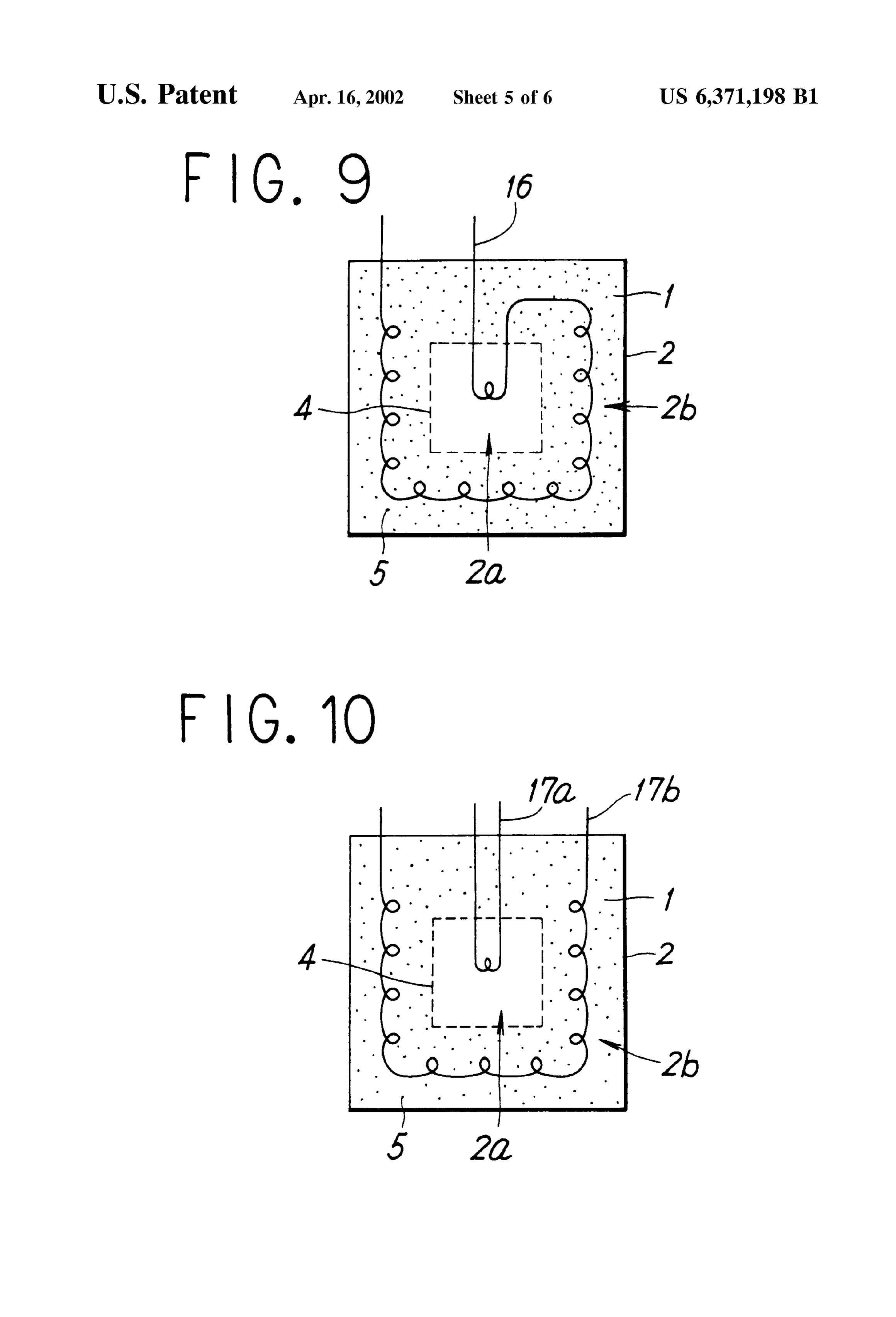
Embodiment 9 The operation in each process is basically the same as that FIG. 9 is a sectional view of another embodiment of the of the embodiment 1. In the injection process of heat, heat Storage device in accordance with the present invention. procedure varies in accordance with the following three This heat Storage device has basically the same construction 50 CSCS.
as the embodiment shown in FIG. 1, and provides a heat A first procedure is adopted when the temperature of the Storage tank 2 with an heat eXchanger 16 disposed So as to heat Source is higher than that of the central portion 2a of the Sequentially pass the central portion 2a and the outer portion heat Storage material 1, and at the same time, when the 2b, for executing a heat eXchange between the outside. Also, quantity of the heat of the heat Source is more than heats the a liquid-absorbent material 5 is dispersed in the heat Storage 55 central portion 2a. At this time, the heat transfer medium material 1 of the outer portion 2b partitioned by a net 4 in which exchanges heat with the outside is first Sent from the the heat Storage tank2. With regard to the heat eXchanger 16, heat Source to the heat eXchanger 17a, and heats the heat the constitutions Such as material, the cross-sectional profile, Storage material 1 of the central portion 2a, being then and the presence or absence of a fin is not limited, as long returned to the outside. However, Since the temperature of as the heat eXchanger 16 has a Stability toward the heat 60 this heat transfer medium returned is higher than that of the Storage material 1. heat Storage material 1 of the outer portion 2b, the heat Next, an explanation is presented of the operation of the transfer medium is next sent to the heat eXchanger 17b, and heat Storage device in the case where a higher temperature heats the heat Storage material 1 of the outer portion 2b, than that of the external environment is stored in the heat being then returned to the outside. This makes it possible to storage device shown in FIG. 9. 65 rapidly heat the heat Storage material 1 of the outer portion The operation in each proceSS is basically the same as that 2b and to improve the efficiency of heat eXchange in the heat of the embodiment 1. In the injection process of heat, firstly Source. This is because the temperature difference at heat
Page 16
eXchange in the heat Source becomes large as compared with central portion 2a, and at the same time, when it can be met the case where only the heat Storage material 1 of the central by the quantity of heat extracted from the central portion 2a. portion 2a is heated, since the heat transfer medium Sent At this time, the heat transfer medium from the outside is from the heat Source is returned thereto with the temperature Sent to the heat eXchanger 17a, and is heated by the heat decreased. Storage material 1 of the central portion 2a, being then A Second procedure in the injection process of heat is returned to the outside for utilizing. adopted when the temperature of the heat Source is higher A third procedure in the extraction process of heat is than that of the central portion 2a of the heat Storage material adopted when the temperature of the heat needed at the 1, and at the same time, when the quantity of the heat of the outside is lower than that of the heat Storage material 1 of the heat Source is all that is needed to heat the central portion 2a. central portion 2a, but at the same time, when it is higher At this time, the heat transfer medium from the heat Source than that of the heat Storage material 1 of the Outer portion is Sent to the heat eXchanger 17a, and heats the heat Storage 2b. is
In this case, the heat transfer medium from the outside heated by the heat exchanger 17b, and then it is returned material 1 of the central portion 2a, being then returned to to the outside the heat Source. Although the temperature of this heat medium is Sentforfrom utilizing. If the whole of the heat transfer the outside to the heat eXchanger 17a, transfer medium returned from the 17a is higher than that of 15 the temperature of the heat Storage material 1 of the central the heat Storage material 1 of the Outer portion 2b, further portion 2a having a higher temperature than the outer heat transfer medium can not be sent to the heat eXchanger portion 2b is reduced, which causes a decrease in the 17b, unlike the case of the first procedure. This is because temperature of the heat Storage material 1 existing in the the quantity of heat of the heat Source in this case is not central portion 2a having a temperature higher than that of Sufficient, and hence the heat transfer medium which has the outer portion 2b. This is undesirable because the effec further decreased in temperature as a result of usage of the tive energy (exergy) of the heat Storage device is rendered heat eXchanger can not be heated by the heat Source to a less, even if the quantity of heat to be extracted from the heat higher temperature than that of the heat Storage material 1 of Storage device to the outside is the same. the central portion 2a, with the result that a circulation A third procedure is to prevent the reduction in the wherein heat Starts from the heat Source and returns thereto 25 effectiveness of heat Storage device as much as possible, by via the heat exchangers 17a and 17b can not thermally exist. extracting the heat from a Suitable portion of the heat Storage A third procedure in the injection process of heat is material required 1 corresponding to the temperature of the heat by the outside. This makes it possible to provide a adopted when the temperature of the heat Source is lower than that of the central portion 2a of the heat Storage material heat Storage device that efficiently operates in Spite of a wide 1, and at the Same time, when it is higher than that of the heat variation in Supply and demand of heat. In this embodiment, a case where the heat Storage tank and the like are similar to
Storage material 1 of the outer portion 2b. In this case, the those in the embodiment 1 is shown, but Similar operations heat transfer medium is Sent to the heat eXchanger 17a, and heats the heat Storage material 1 of the outer portion 2b, to the foregoing can be achieved also in the case of Such being then returned to the heat Source. Since the temperature constructions as shown in the embodiments 2 through 8. of the outer portion 2b lies between the temperature of the 35 Incidentally, when the heat of a temperature lower than central portion 2a and the that of environment outside the that of the environment outside heat Storage device is Stored heat Storage device, it is possible to cause the heat Storage in the Storage device of each embodiment, only the high device to efficiently Store the energy of the heat Source by lower relation of temperature between the Storage device using the heat eXchanger 17b alone, even if the temperature and the external environment, and the direction of heat flow of the heat Source is not Sufficiently high. 40 become opposite to those of each of the above-described In the conservation process of heat, as in the case of the embodiments.
a corresponding
However, the basic operation is the Same as embodiment.
embodiment 1, the apparent Viscosity of the heat Storage material 1 of the outer portion2b is high so that the heat loss areThe shape of the heat Storage tank 2 in these embodiments not limited to the cuboid shape as shown in the drawings.
toward the outside is low.
Also in the extraction process of heat, the procedure 45 Variousalso be shapes. Such as cylindrical, or Spherical shape may adopted.
varies in accordance with the following three cases. What is claimed is:
A first procedure is adopted when the temperature of the 1. A heat Storage device comprising: heat needed at the outside is close to that of the heat Storage material 1 of the central portion 2a, and at the same time, a heat Storage tank charged with a heat Storage material when it can not be met by only the heat of the central portion 50 for Storing heat from outside the heat Storage tank, Said 2a. At this time, the heat transfer medium exchanging heat heat Storage tank having a central portion and an outer with the outside is first sent from the heat Source to the heat portion, Said outer portion Surrounding Said central eXchanger 17b, and is preheated by the heat Storage material portion;
1 of the outer portion 2b, being then once returned to the heat eXchange means for executing an injection and an outside. Since the temperature of the heat transfer medium 55 extraction of heat between inside and outside the heat returned from the heat exchanger 17b is lower than that of Storage tank by heat eXchange between Said heat Stor the heat Storage material 1 of the central portion 2a, the heat age material and a heat transfer medium, Said heat transfer medium is next sent to the heat eXchanger 17a, and eXchange means being disposed So that the central is heated by the heat Storage material 1 of the central portion portion and outer portion of Said heat Storage tank are 2a, being then returned to the outside. This makes it possible 60 caused to Sequentially perform heat eXchange with to rapidly extract the heat of the heat Storage material 1 of Outside the heat Storage tank, the outer portion 2b and to SuppreSS a rapid temperature Suppressing means for Suppressing natural convection of decrease of the central portion 2a caused by a large load the heat Storage material, Said Suppressing means being from the outside. disposed in the outer portion of the heat Storage tank, A Second procedure in the extraction process of heat is 65 and adopted when the temperature of the heat needed at the a partitioning device positioned between Said central and outside is close to that of the heat Storage material 1 of the Outer portions of Said heat Storage tank and configured
Page 17
to be permeable for the heat Storage material and a partitioning device positioned between Said central and impermeable for the Suppressing means. Outer portions of Said heat Storage tank and configured 2. A heat Storage device as claimed in claim 1, wherein to be permeable for the heat Storage material and Said partitioning device comprises a net. impermeable for the Suppressing means. 3. A heat Storage device comprising: 4. A heat Storage device as claimed in claim 1, wherein a heat Storage tank charged with a heat Storage material Said Suppressing means comprises a liquid-absorbent mate for Storing heat from outside the heat Storage tank Said rial dispersed in the heat Storage material or the heat transfer heat Storage tank having a central portion and an outer medium in the Outer portion of the heat Storage tank. portion, Said outer portion Surrounding Said central portion; 5. A heat Storage device as claimed in claim 3, wherein heat eXchange means for executing an injection and an Said partitioning device comprises a net. extraction of heat between inside and outside the heat 6. A heat Storage device as claimed in claim 4, wherein Storage tank by heat eXchange between Said heat Stor Said liquid-absorbent material comprises at least one of a age material and a heat transfer medium, Said heat polymer particles capable of a high water-absorbency and a eXchange means being positioned to execute heat 15 fiber material.
eXchange between the central portion of Said heat 7. A heat Storage device as claimed in claim 6, wherein Storage tank and outside the heat Storage tank, Said polymer particles capable of a high water-absorbency Suppressing means for Suppressing natural convection of comprises Starch-acrylonitrile graft polymeric hydrolysate, the heat Storage material, Said Suppressing means being and Said fiber comprises absorbent cotton. disposed in the Outer portion of the heat Storage tank, and
Provenance
- Collection
- Patents citing this work
- Original assignee
- Agency of Industrial Science and Technology
- Pages
- 17
- Method
- pdftotext (the PDF's own text layer) + pdftoppm 300dpi page scans
- Patent office record
- patents.google.com →
- Source
- Google Patents citing-documents table
- Inventors
- Satoshi Hirano; Agency of Industrial Science and Technology
- Published
- 2002-04-16
- Transcribed from
- patentimages.storage.googleapis.com →