patent · US5944089
Thermal storage systems for buildings
31 August 1999
Page 1 — bibliographic record
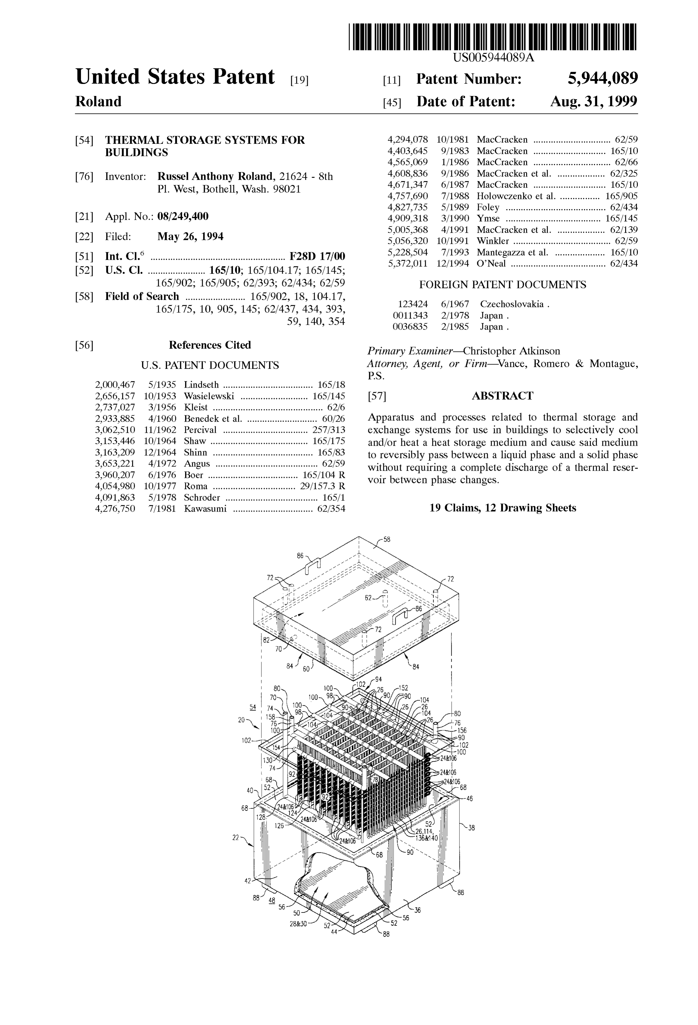
United States Patent (19) 11 Patent Number: 5,944,089 Roland (45) Date of Patent: Aug. 31, 1999 54) THERMAL STORAGE SYSTEMS FOR 4.294,078 10/1981 MacCracken ............................... 62/59 BUILDINGS 4,403.645 9/1983 MacCracken ... 165/10 4,565,069 1/1986 MacCracken ............................... 62/66 76 Inventor: Russel Anthony Roland, 21624 - 8th Y/ -a-
aC-IaCKCIl . . . . . . . . . . . . . . . . . . . . . . . . . . . . .
Pl. West, Bothell, Wash. 98021 4,757,690 7/1988 Holowczenko et al. 165/905 4,827,735 5/1989 Foley .................. ... 62/434 21 Appl. No.: 08/249,400 4.909,318 3/1990 Ymse .................. ... 165/145 5,005,368 4/1991 MacCracken et al. . ... 62/139 22 Filed: May 26, 1994 5,056,320 10/1991 Winkler ....................................... 62/59 6 5,228,504 7/1993 Mantegazza et al. ... 165/10 51) Int. Cl. ...................................................... F28D 17/00 5,372,011 12/1994 O'Neal ...................................... 62/434 52 U.S. Cl. ....................... 165/10; 165/104.17; 165/145;
165/902; 165/905; 62/393; 62/434; 62/59 FOREIGN PATENT DOCUMENTS 58 Field of Search ........................ 165/902, 18, 104.17, hoslovaki 165/175, 10, 905, 145; 62/437, 434, 393, 123424 6/1967 Czechoslovakia.
56) References Cited Primary Examiner-Christopher Atkinson
2,000,467 5/1935 Lindseth .................................... 165/18 2,656,157 10/1953 Wasielewski . ... 165/145 57 ABSTRACT 2,737,027 3/1956 Kleist ............................................ 62/6 2,933,885 4/1960 Benedek et al. ... 60/26 Apparatus and processes related to thermal Storage and 3,062,510 11/1962 Percival ........ ... 257/313 eXchange Systems for use in buildings to Selectively cool 3,153,446 10/1964 Shaw ..... . . 165/175 and/or heat a heat Storage medium and cause Said medium 3,163,209 12/1964 Shinn ........................................ 165/83 to reversibly pass between a liquid phase and a Solid phase
"Iosif without requiring a complete discharge of a thermal reser 4,054,980 10/1977 Roma ... ER voir between phase changes.
4,091,863 5/1978 Schroder ..................................... 165/1 4,276,750 7/1981 Kawasumi ................................ 62/354 19 Claims, 12 Drawing Sheets
Page 2
Drawing sheet — no readable text.
Page 3
TL I L St AAAA "I I I
| .a . ' . . . . Y. \\A.l cCdw" -
Ezza Aziz Aziz A.A.A.A.A.A.V.A.A2-SOH9
LL AAAAAYAA Z777-Z.ZZ
s 1EEEEEy/AAAAZAzizi Aaaay! AAAAAAAA zzzzzzzzz ziz,777,777-sGC
Lifestigiit is firefits. Dis NYess
Niigisilii
AAAAAAAAAYAa ls
E. aarzzzzzi GS
FEEEE
Ezzazza AZAAAAAAZZZZZZZZZZ Eää Ézi:ŽižEs-GSE N- to NC
Azazzazzaz A-AA-AA-A2
zAAAAAAA 4AZAAYAZAAAAA-Bet
SEAZXYZZZZZáxy
Dia
SSNS
Nos 53
rs conds
SNSNS
SSNS
ALLIE
Page 4
C Co C w Cd C C Cd Cd oC H H yr- S3 v- wn H vrr v- n ces cin So cSo So
YSSSSSSSSSNYSSASSNSSNYSSY easia alasa 21
LHEE
III
RTRTTTTTTRPRP
III-IIIMIITEIHEIS Rttract tract
IEEIHEITIEIHEIRIPIEIHRIEEIIIESN N
III EIFIEitilitiFitEiEIHis
IEEEIHIEEEIHEIEIEIEEIHEIHIP
FIFEIETEIEEIFIEEIEEIHEIEEI
I IHIEEIRIEEIETEIEEIHEI)
EIEEIEEETETELEETELEI
IHIEEEIEIEEIEIEEEIPIEEIEIHIS
IEEIIEEMENEI IEEEIEE IETETEllis
HIENRIETIEIEIIRIRIPIETRIETIEPIRIES
IIEEME IPIEEIHTERRIEIPIEEIEHEI
III EIETIEEIETEMEETIENET
IEIEEE IEEEIEEETELETEEIEEI
E III-III-III IIHTS
EIPIRIt
D EE IEEE IEEEEEEEEEEEASE
EmilitiFilipiltilitic
HHHHHHHHHHHHHHHHH)
Page 5
Drawing sheet — no readable text.
Page 6
Drawing sheet — no readable text.
Page 7
Drawing sheet — no readable text.
Page 8
Drawing sheet — no readable text.
Page 9
Seo
Seo
Seo Sco Seo
C) S. S
Nas;
3 W1. It AIA IA IAIEWIAIAIAIA/FS) is
NNEEE
DDDCU
C LUL
cres
TEEEEEEE EEEEEEEEIS) isis all ill C m
EEEEEEEEEEEEEEEEEEEE on
C HEEEEEEEEEEEEEEEEEES
H CCC 111
CEEEEEEEEEEEEE CS
ESEEEEEEE EIHEIRIS
SIEEEEEEEEEEEEEE
I III IIHIII
IIIs lettetter Fe2 S.
EEI-IEIHEITE HEIHEIHIEEIEEE IIIs Cd SEEEEEEEEEEEEEEE|Eas rH
B-121121111121121.21111-12 arror
EEEEEEEEEEEEEEEEE
sEEEEEEEEEEE
lic
TTTTTTTTTT 22) d CCCCCCHS can CN EEEEEEEEEEEEEEEEEE|2 n
EEE EEEEEEEEEE|3}}
EEEEEEEE-E-E--CYN Os
E-TFEP|| |||||PIPE|| ||23 C
III. If II
fiO &
Page 10
Drawing sheet — no readable text.
Page 11
FIG. 11 26& 14&36 2684 24806 2O 248106 76 156 N Y 7 / C-80
JNN
SNILS isis || |s sists 90 94 to
S-SS Nis NSS1IN N
F USS TNT S TST ISSISTR
100 104 5 s NSN 28."
NNNNN
NO-2E2ESS Tit,
7874J/T. A 2I I I INC
Page 12
seaser t-NSL INS INS INSTINI
104 NRJ IN
SNNN IN IN
NS S SNSSSS N-I-HSNN 94
NSN N N 1NSSE
S. SS NRNHT
Ssssssssss
OSISTNTISTST Iss-
Nist NS NS NS Niss 100
s NNNNNN
SSNsN St loo /9
- UNITTTTTTTTTTF OO
158 Niel lihyllii Illi 122 1
128- 74 122 120 19420 120
Page 13
Drawing sheet — no readable text.
Page 14
THERMAL STORAGE SYSTEMIS FOR During the charging phase of the thermal Storage System, BUILDINGS the condenser is generally located outside the building So that heat generated during the condensing phase can be
COPYRIGHT NOTICE expelled into the atmosphere, whereupon the refrigeration (a) Copyright 1994, James R. Vance. All Rights Reserved. proceSS begins again.
A portion of the disclosure of this patent document theDuring a discharging phase of the thermal Storage System, contains material that is Subject to copyright protection. The evaporated of process passing liquid or brine Solution, and/or the refrigerant through the System is generally copyright owner has no objection to the facsimile reproduc reversed. Consequently, the piping that is located within the tion by anyone of the patent document or the patent Storage container and is imbedded disclosure, as it appears in the Patent and Trademark Office block of ice, no longer functions as anwithin a nearly Solid evaporator to cool the patent file or records, but otherwise reserves all copyrights water. Rather, Such piping functions as a heat pump, whatsoever.
condenser, or heat eXchanger, to remove Stored thermal
TECHNICAL FIELD energy to cool the building. For example, heated or warm 15 liquid refrigerant can be passed through the piping, where
This invention relates to thermal or heat Storage and upon the liquid refrigerant and piping are cooled by the eXchange Systems that can be used in buildings. More Surrounding block of ice. AS the heated liquid refrigerant and particularly, this invention relates to apparatus and processes Surrounding piping is cooled, the block of ice is slowly Selectively to cool and/or heat a heat Storage medium and melted. Since the block of ice is So large, this cooling effect cause Said medium to pass reversibly between a liquid phase may continue for a Substantial period of time. The cooled and a Solid phase without requiring a complete discharge of liquid or refrigerant can then be used to cool the ambient air a thermal reservoir between phase changes. temperature of the building. BACKGROUND OF THE INVENTION The following patents describe specific apparatus and processes related to air conditioning Systems and heat
Since the advent of residential and commercial air con 25 exchangers: Kleist (U.S. Pat. No. 2,737,027, issued Mar. 6, ditioning Systems, many ingenious apparatus and processes 1956); Benedek et al. (U.S. Pat. No. 2,933,885, issued Apr. for cooling ambient air temperatures within buildings have 26, 1960); Percival (U.S. Pat. No. 3,062,510, issued Nov. 6, been created. One general concept is almost universally 1962); Shinn (U.S. Pat. No. 3,163,209, issued Dec. 29, utilized throughout Such Systems. That concept is to use a 1964); Angus (U.S. Pat. No. 3,653,221, issued Apr. 4, 1972); refrigeration process to change a heat Storage medium from Boer (U.S. Pat. No. 3,960,207, issued Jun. 1, 1976); Roma a liquid State to a frozen Solid State, and then use the coolneSS (U.S. Pat. No. 4,054,980, issued Oct. 25, 1977); Schroder stored within the frozen medium to cool the ambient air of (U.S. Pat. No. 4,091,863, issued May 30, 1978); Mac the building. Cracken (U.S. Pat. No. 4,294,078, issued Oct. 13, 1981); For example, many commercial ice Storage or thermal 35 MacCracken (U.S. Pat. No. 4,403,645, issued Sep. 13, Storage air-conditioning Systems typically include a large 1983); MacCracken (U.S. Pat. No. 4,565,069, issued Jan. Storage container that is filled with a heat Storage medium 21, 1986); MacCracken et al. (U.S. Pat. No. 4,608,836, Such as liquid water, a fluid brine Solution, or other phase issued Sep. 2, 1986); MacCracken (U.S. Pat. No. 4,671,347, change material (PCM). For purposes of easy understanding issued Jun. 9, 1987); MacCracken et al. (U.S. Pat. No. the term “water will be used to indicate any appropriate 40 5,005,368, issued Apr. 9, 1991); and Pardubice heat Storage medium, including, but not limited to, water, a (Czechoslovakia Patent No. 123,424, issued 1967). brine solution, or other phase-change material (PCM). The inventor believes that the listed disclosures taken A Section of piping is placed within the Storage container alone or in combination neither anticipate nor render obvi So that a Substantial portion thereof is immersed within the ous the present invention. Citation of these disclosures does water. The piping is connected to a refrigeration System. 45 not constitute an admission that Such disclosures are relevant In a Standard refrigeration System liquid refrigerant at or material to the present claims. Rather, Such relate only to high preSSure is passed through an expansion valve to an the general field of this invention and are cited as consti area of low pressure called an evaporator. AS the liquid tuting the closest art of which the inventor is aware. refrigerant passes from the expansion valve into the evapo DISCLOSURE OF INVENTION rator Some of the refrigerant turns from a liquid to a gaseous 50
Vapor. As a consequence of the liquid refrigerant turning to One of the primary difficulties and shortcomings of the a vapor, the refrigerant loses heat and becomes colder. previously known Systems is that many of Such systems that After the refrigerant passes through the evaporator, the contain water cannot be frozen completely to form a Solid refrigerant enters a compressor and is Subjected to a high block of ice. If that occurs, the system would be completely preSSure. The compressor pumps the refrigerant to a con 55 destroyed or inoperative. For example, Such systems that are denser. AS the refrigerant flows through the condenser, the commonly known as “ice builders” and “ice harvesters' high pressure causes the vapor to condense back to a liquid. cannot be properly operated if the Stored water becomes AS this process occurs, heat is expended and the condenser frozen into a Solid block of ice.
becomes warm. This process is known as refrigeration. Other difficulties and shortcomings of many previously During a charging phase of the thermal Storage System, 60 known Systems is that the process of circulating refrigerant the piping, that is immersed within the contained water, and/or coolant to charge the System must be terminated in functions as an evaporator. Consequently, liquid water that order to begin discharging the System. Surrounds or contacts the piping is quickly cooled and frozen Furthermore, other difficulties and shortcomings of many to form ice. AS the charging phase of the System continues, previously known Systems is that after the water contained the amount of ice Surrounding the piping increases until 65 within the Storage container is converted to a block of Solid nearly the entire Volume of contained water forms a large ice, the System had to be completely discharged before the block of ice. charging proceSS could again begin. In other words, the
Page 15
block of ice had to be completely melted before the freezing time is spent with the System operating in an ineffective and proceSS could be restarted. If the water within the container inefficient manner.
was only partially thawed and the freezing proceSS was Furthermore, at times it is important to discharge the re-initiated, pockets of liquid water could become Sur System as quickly as possible Such as during variations of rounded by ice. AS the liquid water became frozen, the peak load. With the systems heretofore known, the maxi Volume of water would expand exerting tremendous forces mum discharge rate may be exceeded. Consequently, the upon the System. Eventually, the captured water would crack System cannot utilize the Stored coolant fast enough to meet and burst the Surrounding envelope or jacket of ice. If there the demand.
were a Substantial number of liquid water pockets or a In contrast, the present invention has very little limitations Substantial Volume of liquid water encapsulated within the as to its discharge rate. For example, a System using old ice, the apparatus that freezes and thaws the water would technology may require Six (6) to eight (8) hours to com also become damaged and possibly crack or burst as a result pletely discharge. With the present invention, however, the of this phenomenon. If this phenomenon is not avoided, System or thermal reservoir may be completely discharged entire heat Storage Systems can be virtually destroyed. within approximately one (1) hour. This is a significant In other words, without the present invention, refreezing 15 improvement of technology over what was previously a partially discharged System would be disastrous. The known.
extraordinary pressures imparted by the freezing ice would Within an ideal heat storage system, it would be prefer normally burst the tubing and/or the containment System of able to operate the System So that coolneSS may be drawn the previously known Systems. Consequently, engineers of therefrom during periods of high demand and at the instant other refrigerant Systems try to prevent Stratification in their the demand decreases, the System could be recharged. design. The present invention, however, benefits from Strati The present invention is that long awaited ideal heat fication which generates thermal Siphoning and Scrubbing of Storage System.
the ice with convention currents without the use of mechani The present invention is relatively inexpensive and eco cal agitation. In essence, Stratification within the present nomical to manufacture. The invention is relatively simple invention is desired and capitalized upon. 25 to construct and assemble. The invention is also extremely
There are Substantial disadvantages associated with dam Simple to use and is relatively inexpensive to operate. aging the heat Storage System. For example, the financial Furthermore, the invention is efficient, effective, functional, expenses to repair or replace a damaged heat Storage System reliable, reusable, compact, rugged, and durable. can be exorbitant. In addition, a Substantial amount of labor The present invention increases the Speed and Simplifies and time is usually required to repair or replace a damaged the procedure to charge and discharge the thermal reservoir. heat Storage System. Please keep in mind that Such damage The invention requires leSS attention during operation. usually occurs during times of high demand for coolness. It is important to note that this invention permits the near Consequently, the impatience to recharge the System may immediate transition between charging and/or discharging overcome the operator's best judgment to follow Standard 35 of the System, without requiring a complete discharge or recharging procedures. If the System becomes damaged and charge of the thermal reservoir between phase changes. is off-line, Such damage usually occurs on the hottest days Consequently, the thermal reservoir may be partially dis of the year, when the System is needed the most. charged and then recharged without having to completely Another disadvantage with the aforementioned heat Stor discharge the System before recharging can occur. Similarly, age Systems is that only a few Standard sizes are available in 40 the thermal reservoir may be partially recharged and then the marketplace. Frequently, additional Storage tanks and discharged without having to completely recharge the Sys asSociated equipment had to be purchased and installed in an tem before discharging can occur. Therefore, the present effort to accommodate a particular application or meet an invention eliminateSpotential damage to the thermal Storage altered need. Consequently, the resulting System was either and exchange System that otherwise often occurs for failure over-sized or under-sized for the particular application. 45 to completely discharge the System before the System is In addition, once a particular heat Storage System is recharged. In addition, there is no need to completely designed and installed within a building, and then the recharge the System before the System is discharged. This cooling needs of the building change, it is very difficult to advantage is important to allow continued use of the System modify the existing System. It is the inventor's experience to meet variable load demands without having to previously that when additional cooling of a building is required, 50 recharge the entire System.
another large, additional heat Storage System is added to the The present invention has a special benefit in permitting existing System. However, Since only a few standard sizes of its use with a wide variety of differently sized loads or heat Storage Systems are available, the added System usually temperature demands. For example, the present invention overcompensates for the inadequacy of the existing System. may be easily adjusted and/or modified to accommodate Consequently, a larger than needed additional System is 55 nearly any imaginable thermal reservoir need. used. In effect, the building owner is required to purchase, The present invention may be Secured to the building or install, and operate a System that may far exceed the actual may be positioned remotely therefrom. Due to the effective temperature demands of the building. Not only is the initial neSS and compactness of the invention, the present invention expenditure more than is required, but during the entire may also be used in areas of extremely limited access. operational lifetime of the System the owner must pay more 60 Conventional or nonconventional refrigeration money to keep the System operating than if an appropriately equipment, Such as traditional compressors, pumps, sized and configured System had been installed. condensers, tanks, tank liners, and control equipment may Another very important disadvantage of the aforemen also be used with the present invention. Consequently, many tioned heat Storage Systems, is that as a greater Volume of ice existing thermal Storage and eXchange Systems may be is melted, the System becomes less effective in its operation. 65 modified to achieve the purposes of this invention without Consequently, if the System must be completely discharged requiring exorbitant financial expenditures or significant before the recharging proceSS can begin, a greater amount of alteration of the refrigeration equipment.
Page 16
S 6
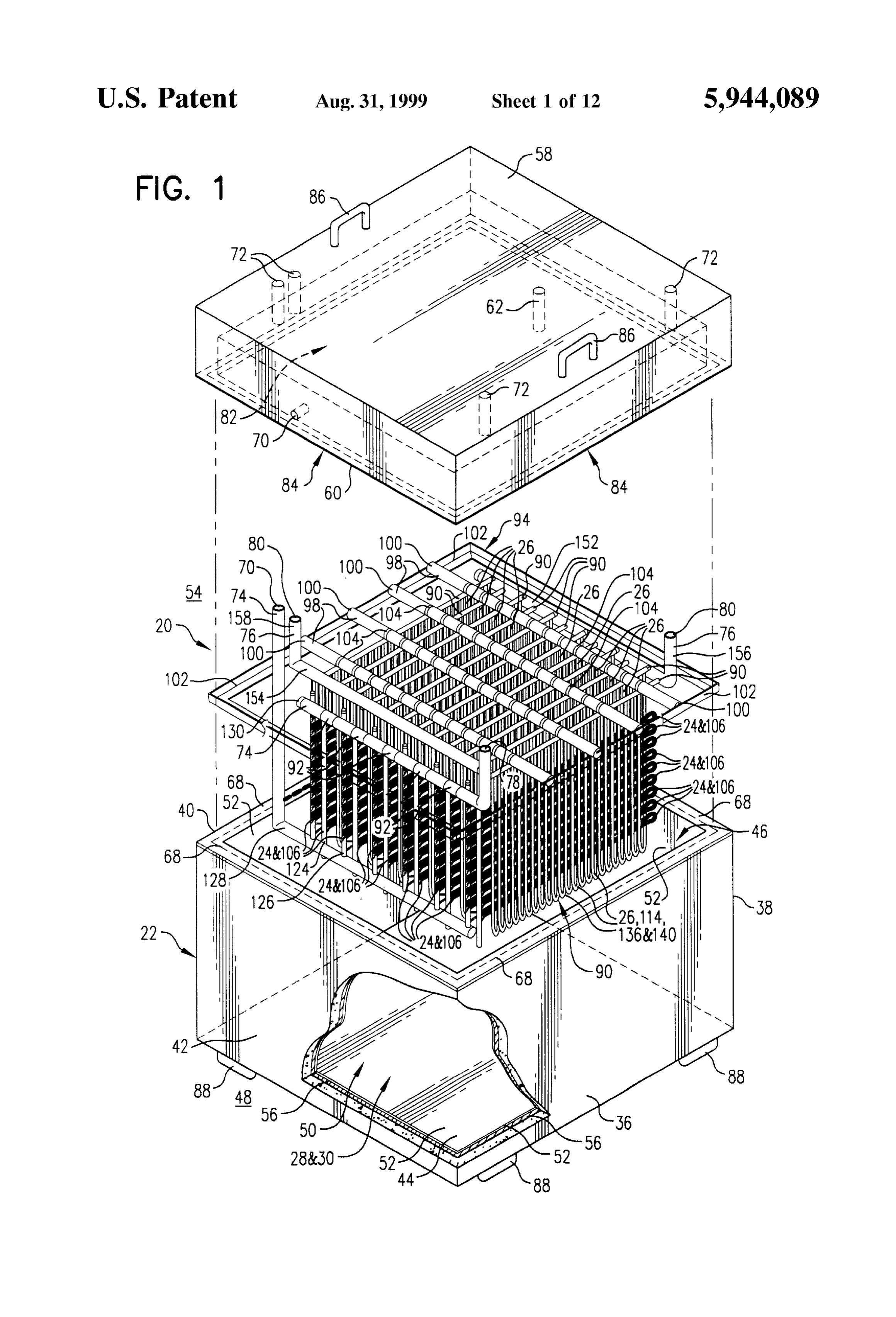
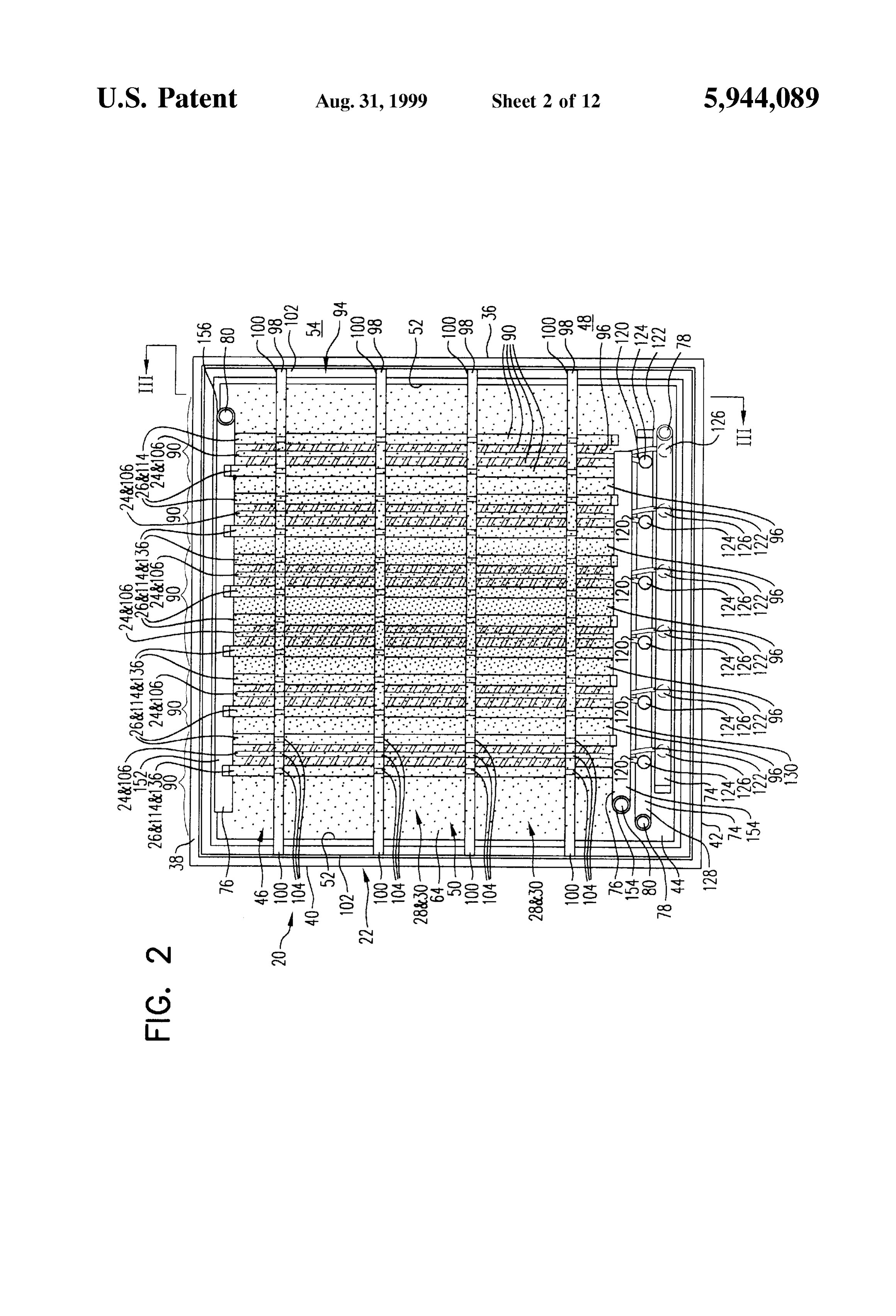
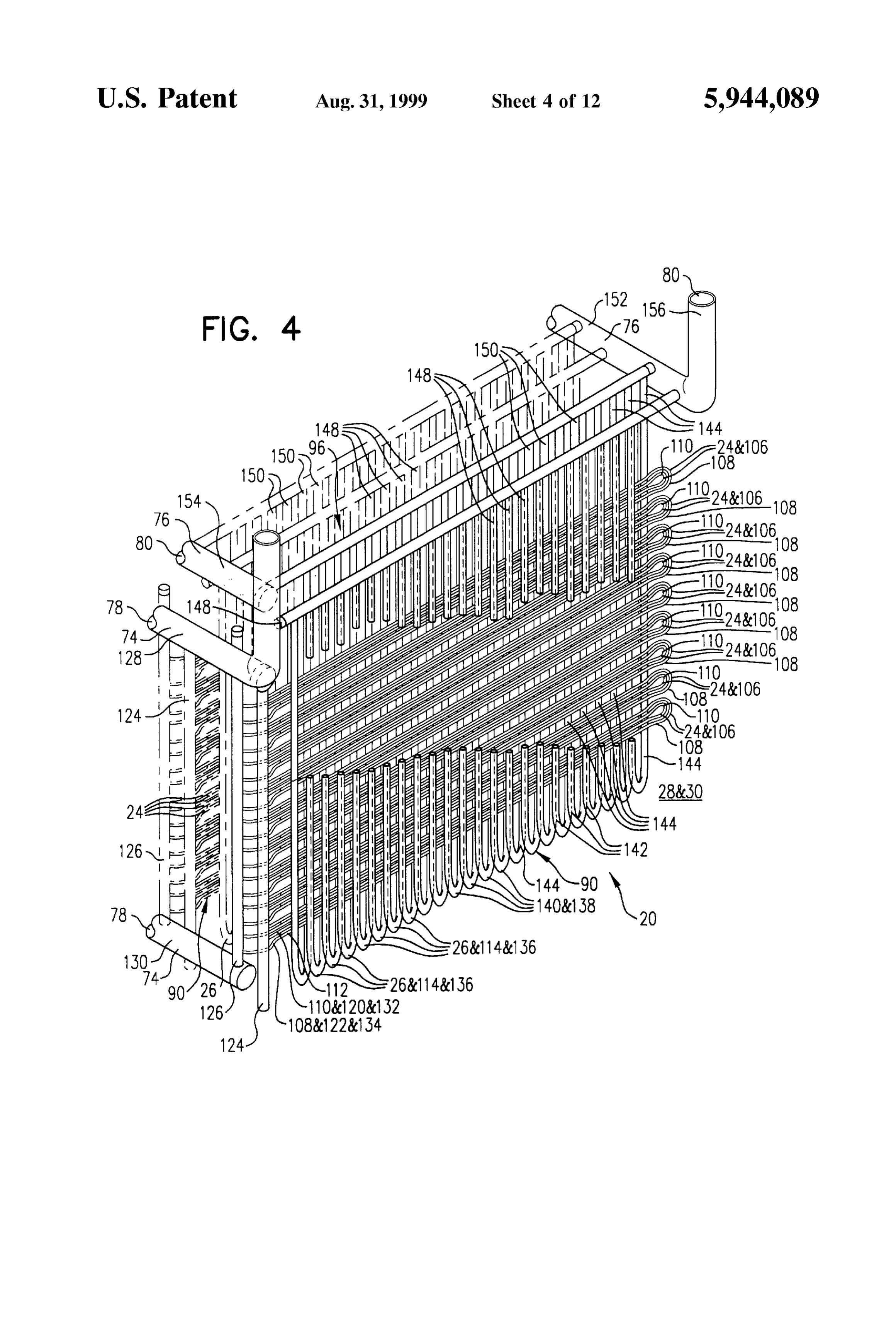
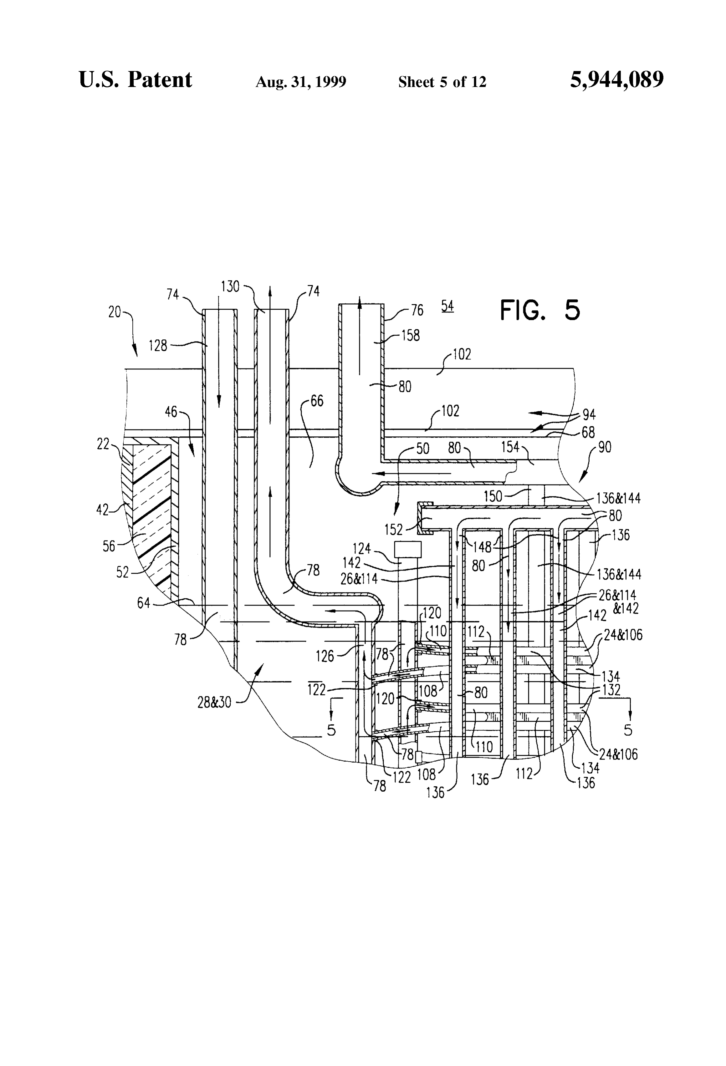
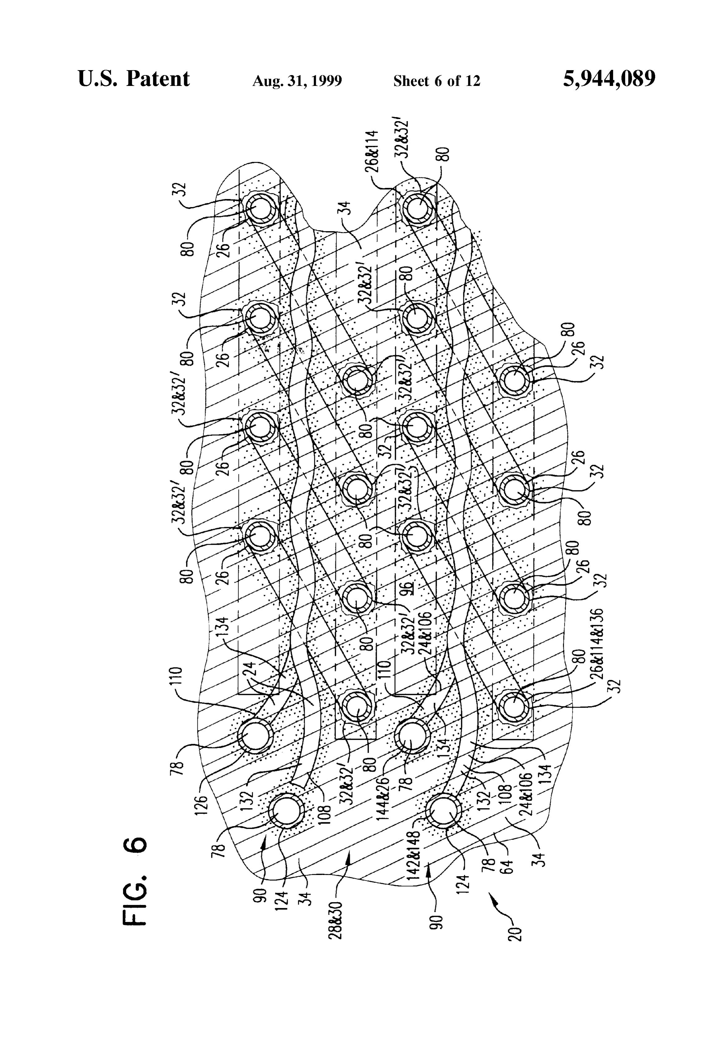
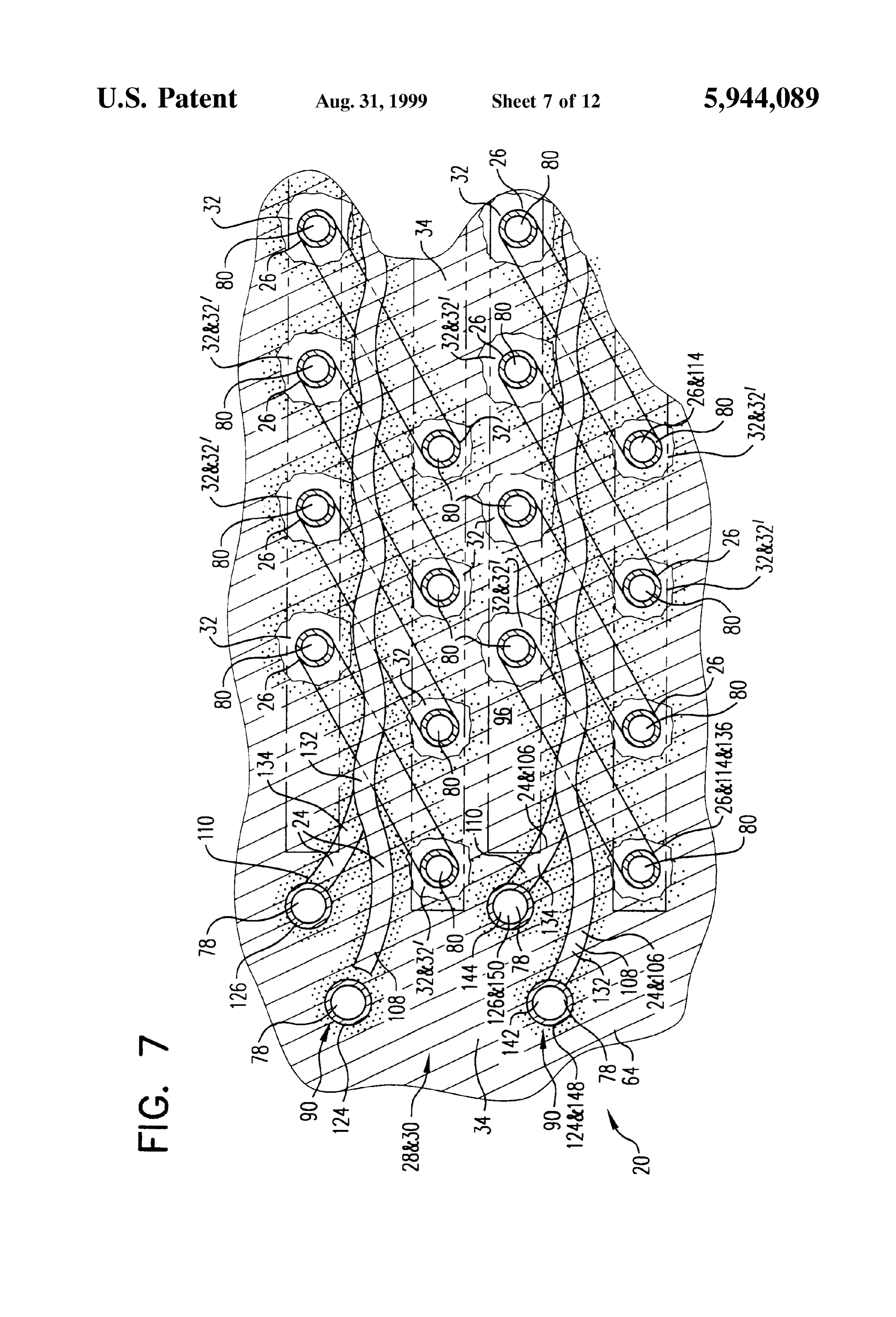
In addition to the foregoing advantages, and other advan FIG. 2 is a plan view of the first embodiment of the tages that will be described further below, the present invention as illustrated in FIG. 1, except with the cover invention also overcomes all of the previously mentioned being removed.
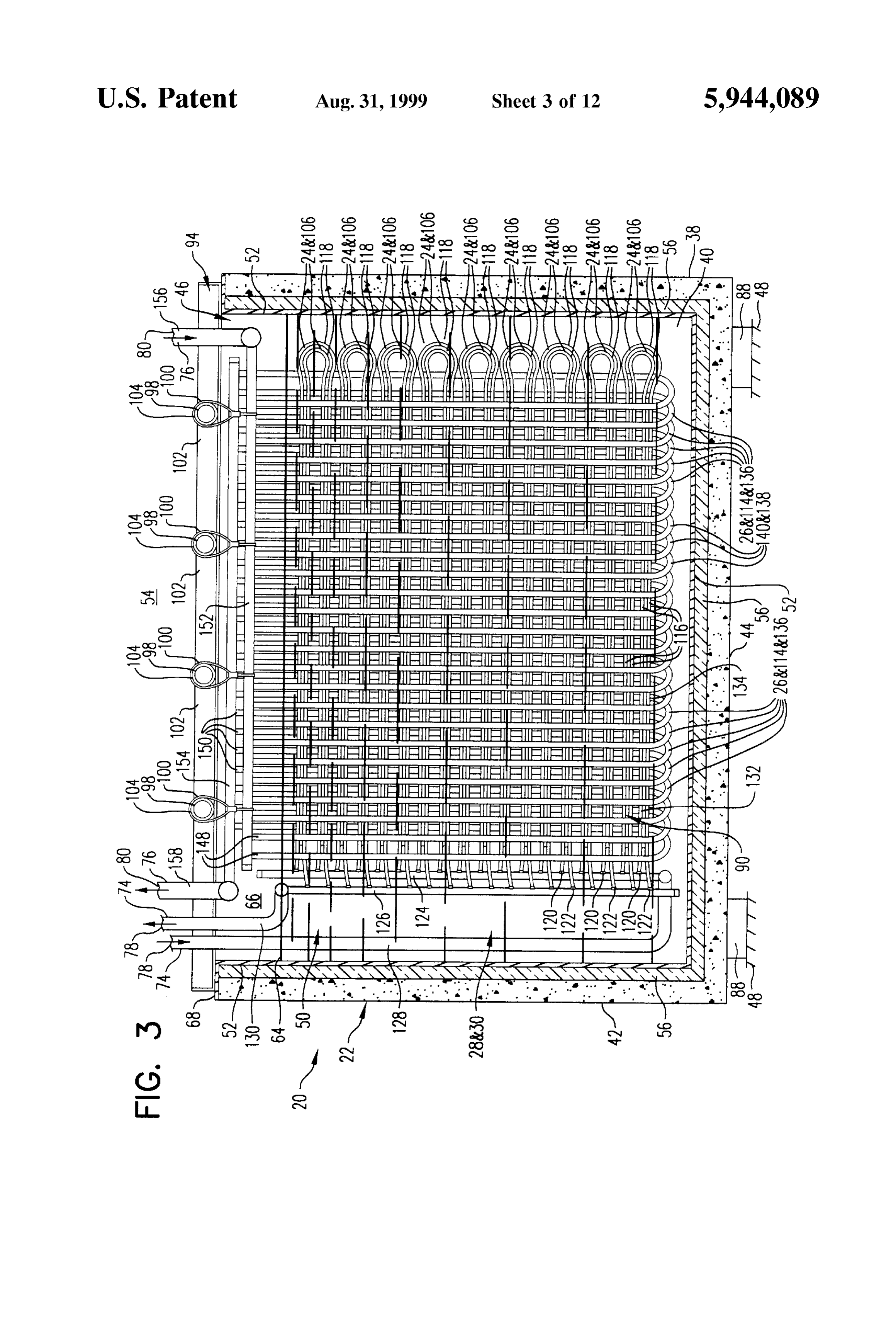
disadvantages. FIG. 3 is a cross-sectional, side-elevational view of the Within the preferred embodiment of the present invention, first embodiment of the invention as viewed from a plane the apparatus generally comprises two intertwined heat generally defined by line III-III in FIG. 2. eXchangers. The two intertwined heat eXchangers are placed FIG. 4 is an enlarged, partial, isometric view of a repre within a housing or container. A Surrounding fluid is then Sentative piping matrix having a portion of a first heat placed within the container. The Surrounding fluid at least eXchanger interwoven with a portion of a Second heat eXchanger as Seen from a plane generally defined by line partially Surrounds and contacts the first heat eXchanger and 1O III-III in FIG. 2.
the Second heat eXchanger. FIG. 5 is an enlarged, partial, cross-sectional, Side The first heat eXchanger is used to make ice. The Second elevational view of an inlet port and an outlet port for the heat eXchanger is used to discharge or melt the ice. first heat eXchanger and an inlet port for the Second heat Both heat eXchanger Systems may be operated at the same 15 exchanger as found within the first embodiment of the time and/or at different rates to meet the load or demand invention.
placed upon the entire System. FIG. 6 is a Schematic, partial, cross-sectional, plan view Each intertwined Set of first and Second heat eXchangers of a portion of the first heat eXchanger interwoven with a defines a panel. The present invention may be expanded or portion of the Second heat eXchanger, wherein the invention contracted for greater or lesser capacity by Simply adding or is near completion of a charging cycle So that the heat removing additional interconnected panels from the System. Storage medium generally assumes a frozen Solid State. Consequently, a System can be custom designed for particu FIG. 7 is a Schematic, partial, cross-sectional, plan view lar thermal load. of a portion of the first heat eXchanger interwoven with a Since each heat eXchanger panel is relatively flat, a portion of the Second heat eXchanger as illustrated in FIG. 6, plurality of panels can be placed within a rectangularly 25 except that the heat Storage medium is shown partially shaped tank or container. This allows for the construction of melted cycle.
as occurs during the initial phases of a discharging a very tight, efficient System.
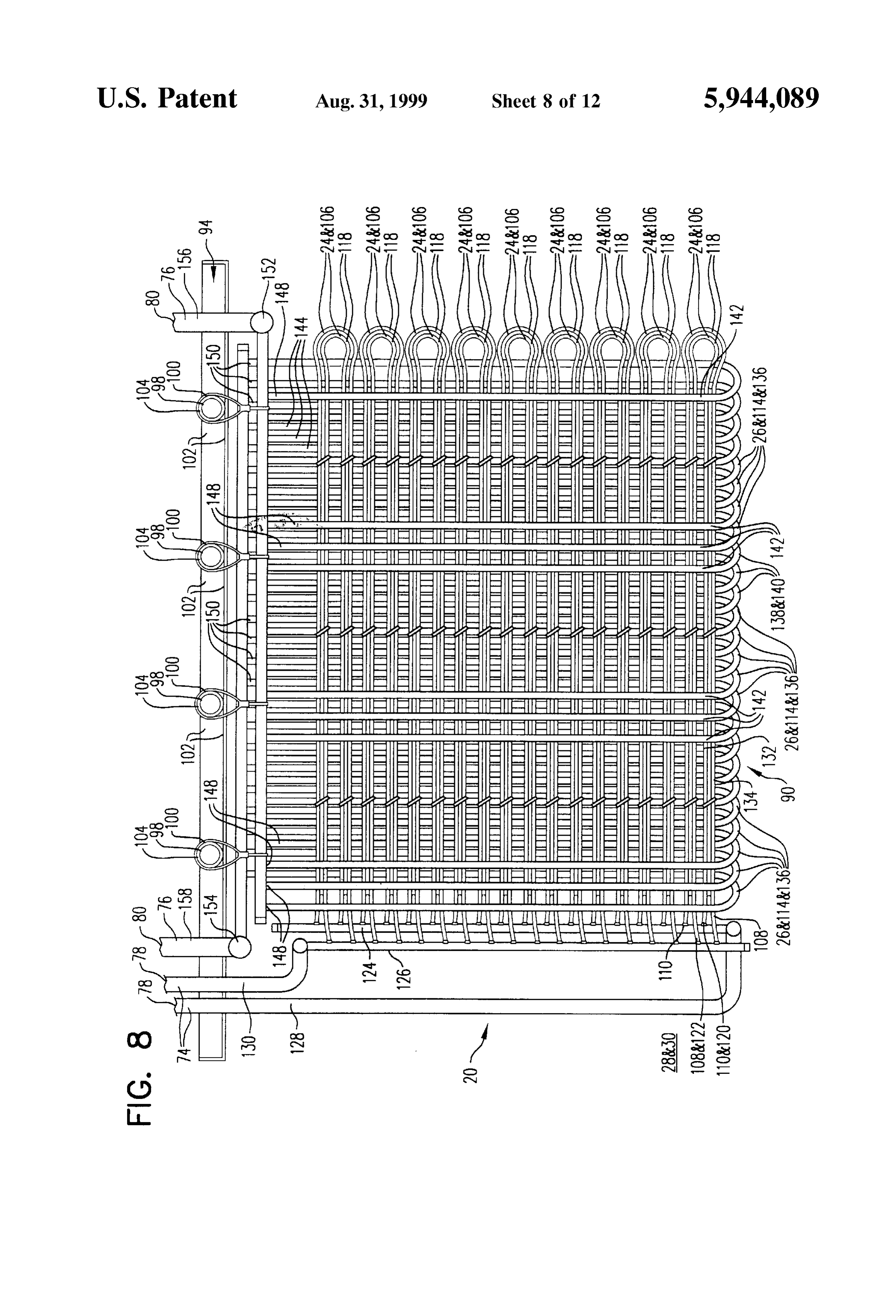
During operation of the invention, a cooled fluid (i.e., tiveFIG.piping8 is a partial, side-elevational view of a representa matrix having a portion of the first heat hydronic Substance) is circulated through the first conduit to eXchanger interwoven freeze the water immediately Surrounding that conduit. AS eXchanger as Seen fromwith a a portion of the Second heat plane generally defined by line this process continues, ice freezes in an even but increas III-III in FIG. 2.
ingly thicker layer about the Second heat eXchanger. The
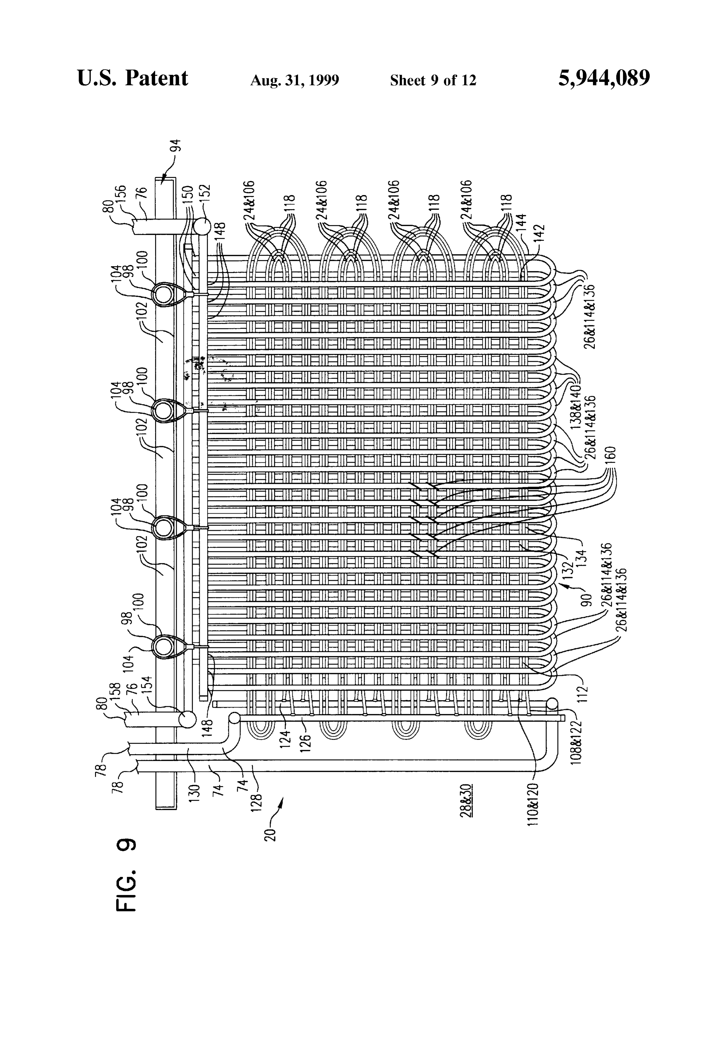
FIG. 9 is a partial, side-elevational view of an alternative water freezes in a direction extending from the first conduit embodiment outwardly. The freezing process may continue until a portion portion of the of a representative piping matrix having a first heat eXchanger interwoven with a portion or the entire volume of water is frozen. 35 of the Second heat eXchanger as would otherwise be seen
At any desired time interval, heated fluid may be circu from a plane generally defined by line III-III in FIG. 2. lated through the Second conduit, thereby melting the water However, FIG. 9 illustrates an alternative embodiment of the immediately Surrounding that conduit. AS the water melts, a invention, wherein different interwoven patterns and loca liquid conduit or tunnel immediately Surrounding the Second 40 tions of attachment are used.
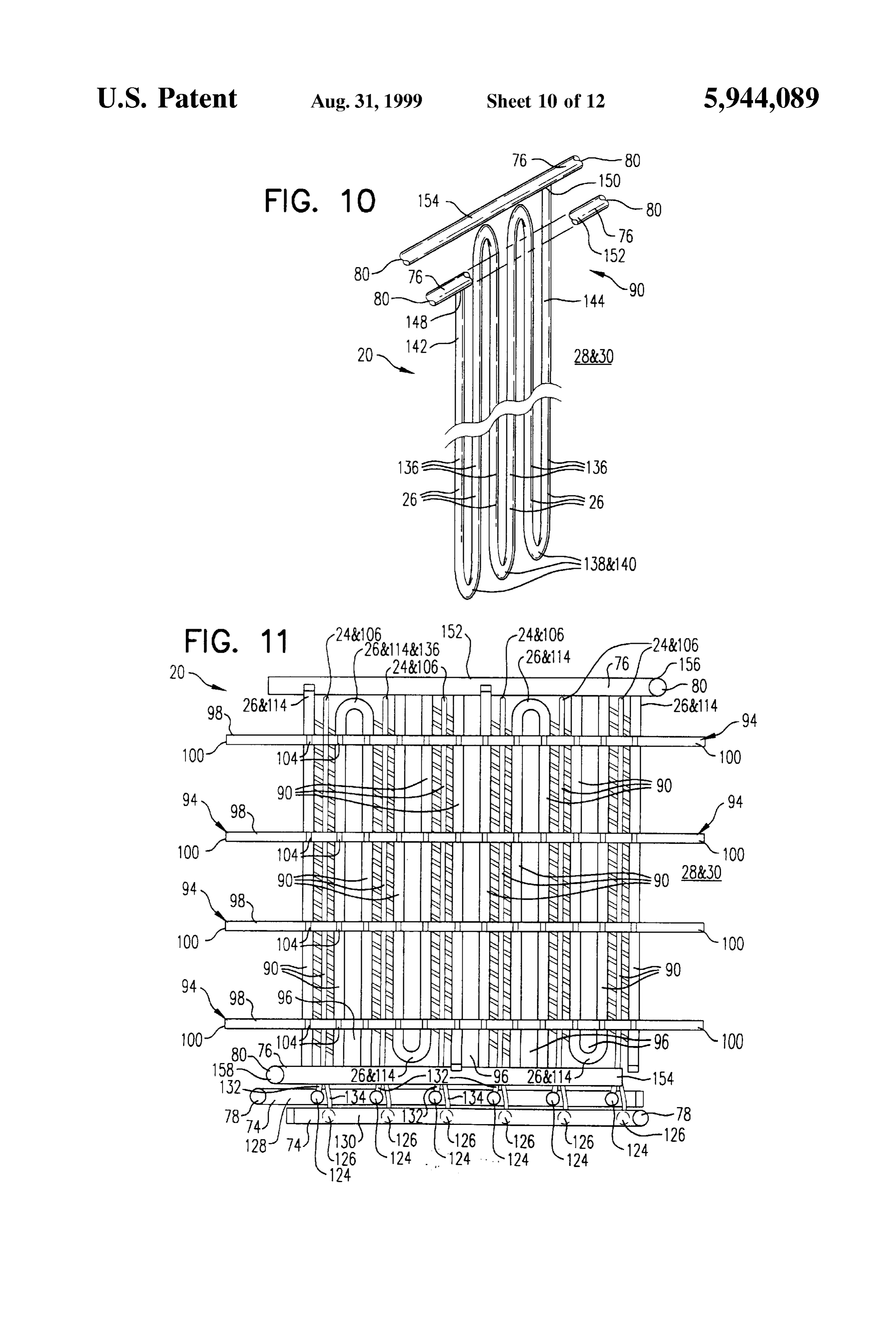
conduit is formed. This process may be used to partially or FIG. 10 is a partial, isometric view of an alternative completely melt the frozen block of ice. embodiment for the Second heat eXchanger of the invention. The physical contact between the first and Second conduit FIG. 11 is a partial, plan view of an alternative embodi or first and Second heat eXchangers actually increase the ment of the invention, wherein the Second heat eXchanger efficiency of the System. More particularly, by having the 45 has a generally Serpentine configuration along a generally cooled first heat eXchanger physically contacting the Second horizontal plane So that at least two adjacent piping matrixes heat eXchanger, the effective thermal Surface area is are interconnected to form a continuous flow path. increased.
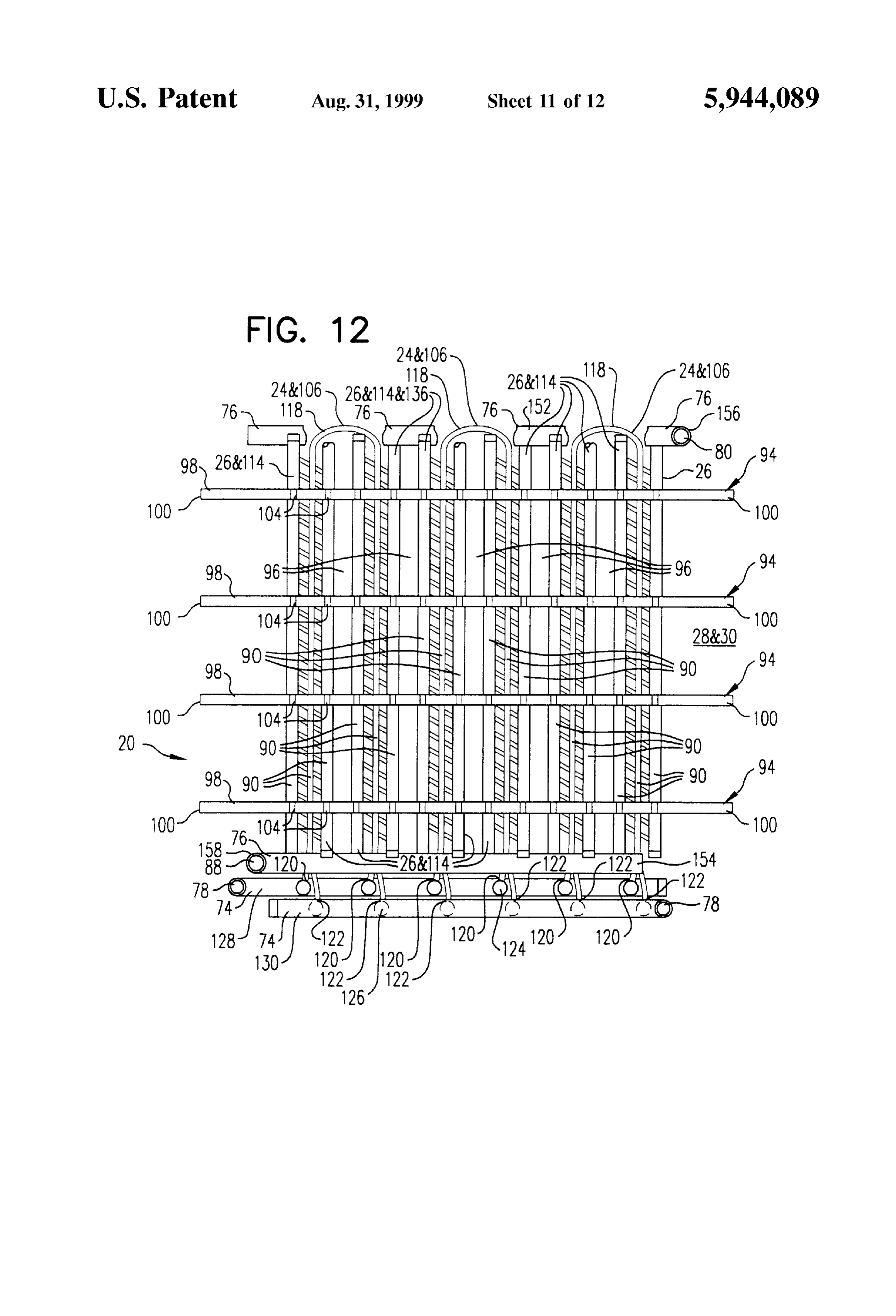
FIG. 12 is a partial, plan view of a further alternative
To achieve these general and Specific objectives the embodiment of the invention, wherein the first heat present invention generally comprises: (a) a housing, (b) a 50 eXchanger has a generally Serpentine configuration along a first heat exchanger, and (c) a Second heat exchanger. Each generally horizontal plane So that at least two adjacent of these elements and their interaction with one another are piping matrixes are interconnected to form a continuous discussed and elaborated upon in great detail within the Best flow path.
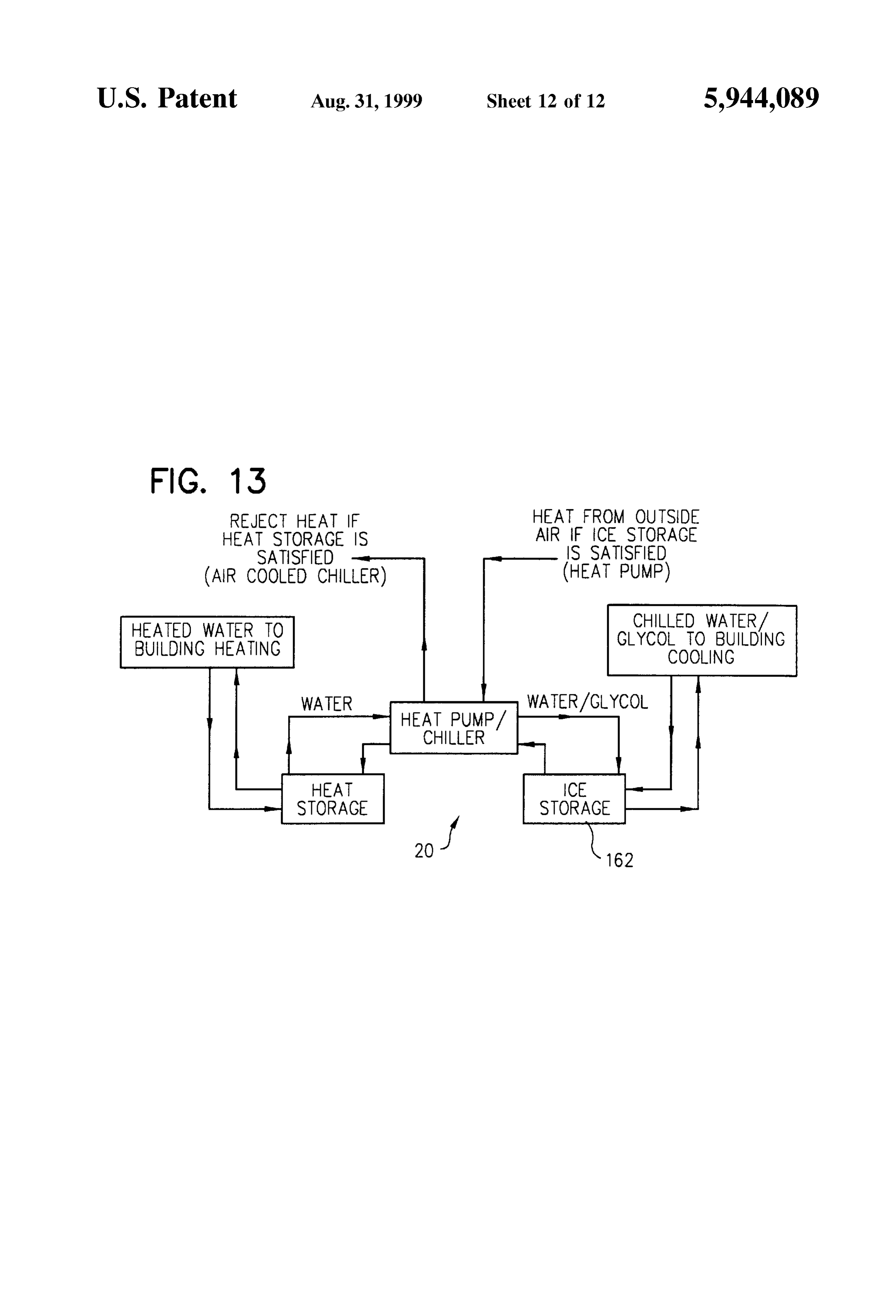
Mode For Carrying Out The Invention portion of this FIG. 13 is a schematic flow chart illustrating the interre disclosure. By this reference, the Subject matter discussed 55 lationship between various components of the invention. therein is expressly included within this portion of the One should understand that the drawings are not neces disclosure.
Sarily to Scale and the elements are Sometimes illustrated by
The present invention achieves each of the above-Stated graphic Symbols, phantom lines, diagrammatic objectives and overcomes the foregoing disadvantages and representations, and fragmentary views. In certain instances, problems. These and other objectives and advantages of the 60 the inventor may have omitted details which are not neces present invention will become more readily apparent upon Sary for an understanding of the present invention or which reading the following disclosure and referring to the render other details difficult to perceive. attached drawings.
BEST MODE FOR CARRYING OUT THE
BRIEF DESCRIPTION OF DRAWINGS 65 INVENTION
FIG. 1 is a partial, cross-sectional, exploded, isometric Referring to the drawings, wherein like numerals indicate view of a first embodiment of the present invention. like parts, to achieve the aforementioned general and Spe
Page 17
cific objectives the present invention generally comprises an the heat storage medium 30. For example, the liner 52 may apparatus 20 having: (a) a housing 22, (b) a first heat comprise sheets of flexible, impermeable, plastic or rubber exchanger 24, and (c) a second heat exchanger 26. To better that physically insulate the heat storage medium 30 from the understand the function and interrelationship of these interior sidewalls 36, 38, 40, and 42 of the housing 22. The components, however, we will first discuss the environment liner 52 may also thermally insulate the heat Storage medium into which Such components will be placed. 30 from the housing 22 and surrounding atmosphere 54. The present invention generally includes various embodi If desired, the housing 22 may also be provided with ments of a thermal Storage and eXchange System that can be additional thermal insulation 56. For example, the additional used to cool temperatures within residential and/or commer thermal insulation 56 may be necessary to adequately insu cial buildings. Of course, this invention could be built on a late the housing 22 if the housing 22 is manufactured from Smaller Scale to accommodate thermal needs of a lesser metal or plastic. The thermal insulation 56 may be placed magnitude or Smaller demand than that which is typically 40, andagainst either the interior and/or exterior sidewalls 36, 38, 42, and/or the floor 44 of the housing 22.
asSociated with a building. The large opening 46 positioned at the top of the housing More particularly, the present invention may be used 15 22 permits the placement of the first heat eXchanger 24 and Selectively to cool and/or draw coolneSS from a thermal second heat exchanger 26 into the enclosure 50. reservoir 28. The thermal reservoir 28 may comprise a large Furthermore, the large opening 46 permits Servicing and volume of heat storage medium 30 that is stored within the maintenance of the apparatus 20.
housing 22. In the preferred embodiment of the invention, as shown in As best seen in FIGS. 6 and 7, the heat storage medium FIG. 1, the housing 22 is also provided with a removable or 30 should be capable of reversibly passing between a liquid hinged lid 58, hood, or roof. The lid 58 enables the large phase 32 and a Solid phase 34. For example, the heat Storage opening 46 to be closed. When the lid 58 is properly medium 30 may comprise any heat absorbing material Such positioned atop the housing 22, the interior or lower Surface as water, brine, glycol Solution, or other phase change lid 60 of the lid 58 defines a ceiling for the enclosure 50. The material (PCM) that can assume a liquid phase 32, fluid state 25 The 58 may be provided with thermal insulation 56. and/or a Solid phase 34, frozen State. lid 58 may also have an air vent 62, ventilating stack, exhaust Stack, hole, or chimney, located therein, which
The housing 22 may take any desirable size, shape, and enables the removal of exceSS atmospheric preSSure held configuration. For example, in the preferred embodiment of within the enclosure 50.
the invention, the housing 22 is manufactured from poured It is the intention of the inventor that only an appropriate and cured concrete to form a large container, tank, Vessel, amount of heat storage medium 30 be placed within the tub, tray, or box having a first side 36, a second side 38, a enclosure 50. For example, the heat storage medium 30 is third side 40, a fourth side 42, an integral floor 44 or base, poured into the enclosure 50 only after the first heat and an opening 46 at the top of the housing 22. exchanger 24 and the Second heat exchanger 26 have already Of course the housing 22 may be manufactured from been placed in position within the enclosure 50. A sufficient other materials. For example the housing 22 may be manu 35 amount or Volume of heat Storage medium 30 is poured into factured from metal, wood, plastic, compacted Soil, com the enclosure 50 until a substantial portion of the first heat posite materials, and the like. eXchanger 24 and the Second heat eXchanger 26 are AS with conventional heat Storage Systems, the housing immersed therein. However, an adequate expansion area above an upper surface 64 of the heat storage medium 30 22 is either Supported by or is Secured to a Support Structure should be maintained. The expansion area basically defines 48. The Support structure 48 may comprise the building 40 a freeboard 66 between the upper surface 64 of the heat itself. For example, the housing 22 may be placed upon roof storage medium 30 and an upper edge or rim 68 of the of the building or upon a floor especially dedicated to sidewalls 36, 38, 40, and 42.
Support mechanical hardware and equipment for the build If needed or desired, the housing 22 and/or lid 58 may be ing.
45 provided with an overflow conduit 70, tube, side vent, or
Alternatively, the housing 22 may be Supported by or be Spillway through which exceSS liquid heat Storage medium Secured to an independent Support Structure 48 that is 30 may be expelled. Overflow conduit 70 is shown in FIG. positioned remotely from the building. 1.
Since the present invention is So dramatically effective The present invention may also or alternatively be pro and efficient during operation, the invention can use a 50 vided with a water-level indicator (not shown) and/or over housing 22 that is much Smaller in size than what would flow protection switch (not shown) that would be activated otherwise be required if a more conventional heat Storage if the upper surface 64 of the heat storage medium 30 System were used. Consequently, the housing 22 of the exceeds a predetermined level.
present invention may be much more compact and may be Holes 72 may be provided within the housing 22 and/or used in areas of extremely limited access. 55 lid 58 to permit the passage of piping 74 and 76 there The floor 44 and Sidewalls 36, 38, 40, and 42 of the through. Thus, the holes 72 permit the ingreSS and egreSS of housing 22 form and define an interior enclosure 50, a refrigerant 78 (or any chilled fluid or gas) and other fluid compartment, or chamber that is capable of housing and and/or gas 80, contained within the piping 74 and 76, containing the heat Storage medium 30 therein. respectively, to pass into and out of the enclosure 50. In essence, the housing 22 defines an ice building Storage 60 Refrigerant 78 may also be referred to as a first fluid orgas tank, wherein the heat storage medium 30 or water may be that is capable of being contained and transported within a contained, frozen and thawed. first conduit 106. Fluid or gas 80 may also be referred to as The housing 22 may also be provided with a liner 52. The a Second fluid or gas that is capable of being contained and liner 52 is preferably positioned within the enclosure 50 transported within a Second conduit 114. between the interior sidewalls 36, 38, 40, and 42 of the 65 If desired, flashing (not shown) may be placed about the housing 22 and the heat Storage medium 30. It is intended piping 74 and/or 76 at each hole 72 to prevent contaminants that the liner 52 be capable of at least partially enveloping from entering into the enclosure 50.
Page 18
As referenced above, the lid 58 may also be provided with to engage or disengage the proper number of curtains 90 for a hinge (not shown) to enable the easy raising and lowering the required task. In essence, each individual heat eXchanger of the lid 58 into place atop the housing 22 sidewalls 36,38, curtain 90 could function separately from the remaining heat 40, and 42. exchanger curtains 90. Valve mechanism 92 is shown in As shown in FIG. 1, a recess 82 and/or seat may be FIG. 1.
positioned about a periphery or rim 84 of the lid 58 to Within a further embodiment of the invention, all heat receive the upper rim 68 of the housing 22 and secure the lid exchanger curtains 90 that are positioned within the enclo 58 in place. If needed and/or desired, a gasket (not shown) sure 50 may be operatively connected to one another. Thus, may be placed about the recess 82 or seat of the lid 58. when the apparatus 20 is operated, all heat eXchanger The lid 58 may also be provided with one or more handles curtains 90 are operated Simultaneously, albeit, possibly at a 86 and/or loops that accommodate the raising and lowering lower rate of efficiency than of what they are capable. of the lid 58. When more than one heat exchanger curtains 90 are used, The housing 22 may also be provided with means for each individual curtain 90 is secured to or suspended from leveling the same. For example, one or more leveling feet 88 15 a Support rack 94, brace, framework, or rig. It is the intention may be attached to, or be formed integrally within, the floor of the inventor that the heat exchanger curtains 90 be 44 and/or sidewalls 36, 38, 40, and 42 of the housing 22. secured to the support rack 94 so that each curtain 90 has a In addition to the leveling feet 88, or alternatively, the Spaced orientation with or relationship to adjacent curtains housing 22 may be provided with one or more Support legs 90, and that a space 96 or crevice be located between (not shown). If needed and/or desired, one or more of the adjacent curtains 90.
Support legs may be provided with a rotatable, height The Support rack 94 may comprise a plurality of beams, adjustable shaft (not shown) and a crank (not shown) that is joists, or girders that generally span across the width or operably connected thereto to enable the proper level the length of the enclosure 50. For example, within the preferred housing 22. embodiment of the invention, the beams of the Support rack The primary function of the first heat eXchanger 24 and 25 94 comprise a plurality of pipes 98 to which each heat the Second heat eXchanger 26 is to Selectively and reversibly exchanger curtain 90 is attached, and from which each heat charge and/or discharge the thermal reservoir 28. More eXchanger curtain 90 is Suspended.
particularly, the primary function of the first heat eXchanger AS can be easily Seen within the Figures, and particularly 24 is to selectively charge the thermal reservoir 28. The within FIG. 1, the beams or pipes 98 have a generally primary function of the Second heat eXchanger 26 is to orthogonal orientation with respect to the generally planar selectively discharge the thermal reservoir 28. heat exchanger curtains 90.
The combination of the first heat exchanger 24 and the AS best seen in FIG. 2, the terminal ends 100 of the beams Second heat exchanger 26 can generally be described as or pipes 98 are Supported within a collar 102 of metal, comprising one or more curtains or panels that are posi L-shaped angle-iron, that is positioned about the upper rim tioned within the enclosure 50 and are at least partially 35 68, edge, ridge, or periphery of the housing 22 Sidewalls 36, submerged within the heat storage medium 30. 38, 40, and 42.
Since both the first heat exchanger 24 and the second heat Any appropriate means 104 to attach or Secure the heat eXchanger 26 are positioned upon the curtain or panel, Such exchanger curtains 90 to the beams or pipes 98 may be used. a combination shall be referred to as a heat eXchanger 40 For example, lengths of rubber or plastic, rope, cord, cable, curtain 90. chains, wire, ties, belts, bands, Straps, buckles, hooks, pins, It is the general intention of the inventor that a plurality Screws, bolts, nails, or any other means for attaching Such of interconnected heat exchanger curtains 90 be used within elements together may be used.
the enclosure 50 and apparatus 20. However, there may be It is generally intended that the heat exchanger curtains 90 a situation wherein only a single heat eXchanger curtain 90 45 be literally suspended within the heat storage medium 30. In is needed. other words, the heat exchanger curtains 90 should be Each heat exchanger curtain 90 may be so sized and spaced above and not contact the floor of the enclosure 50. configured that under predetermined conditions each Such Both the first heat exchanger 24 and the second heat curtain 90 will have a predictable capacity to charge and/or eXchanger 26 operate upon the principle of thermal equilib discharge the Surrounding heat Storage medium 30. 50 rium. In essence, the law of thermal equilibrium States that Consequently, a calculation can be made as to the number of when two bodies having different temperatures are exposed heat eXchanger curtains 90 that must be employed or oper to one another, the temperature of both bodies will change ated to meet or exceed any particular air conditioning and/or until a uniform temperature is attained between both bodies. refrigeration load or demand. If more cooling capacity is In other words, the warmer body will become cooler and the needed, then more heat eXchanger curtains 90 may be used 55 cooler body will become warmer until an equilibrium or and/or employed. balance in temperature is reached. Within one embodiment of the present invention, each In very general terms, the first heat eXchanger 24 defines heat eXchanger curtain 90 functions as a separate cassette, or is connected to a refrigeration System. The refrigeration magazine, or cartridge that can be added as needed to the System is used to remove heat from the heat Storage medium apparatus 20. The engagement of additional heat eXchanger 60 30, thereby freezing the medium 30. Once the heat storage curtains 90 may be accomplished by their physical attach medium 30 is frozen, the coolness stored therein can be used ment to the remaining apparatus 20, as would occur when an when a demand arises. Any appropriate means to reduce the originally installed apparatus 20 is being altered or modified temperature of the heat storage medium 30 may be utilized. for greater cooling capacity. In very general terms, the Second heat eXchanger 26 also Alternatively, a Sufficient number of heat eXchanger cur 65 defines or is connected to a refrigeration System, albeit a tains 90 may be initially placed within the enclosure 50, and different refrigeration System. However, this Second refrig then a switching device or valve mechanism 92 may be used eration System is used to remove heat from a particular
Page 19
application Such as from the air located within a building, medium 30, and yet withstand the nearly constant tempera cold Storage area, or the like. ture and Volume changes that occur within the frozen heat The means to accomplish this task is the thermal exposure storage medium 30. For example, the first conduit 106 may of the Second heat eXchanger 26 to the frozen heat Storage be manufactured from rubber, plastic, ethylene-propylene medium 30. In other words, thermal exposure of the fluid or terpolymer (which is commercially known as EPDM), from gas 80, contained within the Second heat eXchanger 26, to radiant heat tubing, and/or from any other appropriate mate the lower temperatures of the frozen heat storage medium 30 for rial. The inventor prefers to use flexible radiant heat tubing reduces the temperature of the fluid or gas 80. the first conduit 106.
Conversely, thermal exposure of the cooled heat Storage As best seen in FIGS. 4 and 5, the preferred flexible medium 30 to the heated fluid or gas 80 causes the heat 1O radiant heat tubing is manufactured to have two parallel storage medium 30 to absorb heat therefrom, which further tubes 108 and 110 that are spaced apart by a webbing 112 melts the medium 30 to a liquid state. that spans therebetween.
However, the cooled fluid or gas 80 may be transported to It is also preferred that the first conduit 106 be manufac a remote site to absorb heat from a desired application. 15 turedof from a generally flexible material having a coefficient thermal conductivity of about 0.02 to 10.0 BTU-FT/FT--
Once the heat Storage medium 30 reaches a predetermine H-F. Within the preferred embodiment of the invention, the State of discharge, the first heat eXchanger 24 may be first conduit 106 is manufactured from a material being sold activated to recharge and reduce the temperature of the heat under the trademark RADIANTROLL that has a coefficient storage medium 30. of thermal conductivity of about 0.081 BTU-FT/FT-H-F. The particular design of the first heat eXchanger 24 and the Second heat eXchanger 26, and their interrelationship the heat exchanger curtain 90ofwill
The particular placement the first conduit 106 within be discussed following a with one another will now be discussed. description of the Second heat eXchanger 26. A primary element of the first heat eXchanger 24 is a A primary element of the Second heat eXchanger 26 is a length of hollow tubing that forms and defines a generally length of hollow tubing that forms and defines a generally continuous first conduit 106. The first conduit 106 should be 25 continuous second conduit 114. The second conduit 114 capable of being at least partially positioned within the should also be capable of being at least partially positioned enclosure 50. More particularly, the first conduit 106 is within the enclosure 50. More particularly, the second capable of being at least partially Submerged within the heat conduit 114 is capable of being at least partially Submerged storage medium 30 contained within the enclosure 50. within the heat storage medium 30 contained within the The first heat eXchanger 24 functions as means for enclosure 50.
decreasing the temperature of the heat Storage medium 30. The Second heat eXchanger 26 functions as means for To accomplish this task, the refrigerant 78 or other chilled increasing the temperature of the heat Storage medium 30, or fluid is placed within and passed through the first conduit in other words, for drawing coolness from the frozen or 106 of the first heat exchanger 24. Within this document, the nearly frozen heat storage medium 30 for use within the term refrigerant is used to define both what would be 35 building or another application.
considered a traditional refrigerant, Such as ammonia or To accomplish this task, a fluid or gas 80 is placed within other chemical, and a chilled or cooled fluid, Such as but not and passed through the Second conduit 114. In essence, the limited chilled water, brine or glycol Solution. Second conduit 114 defines and functions as a radiator Any appropriate means for decreasing the temperature of through which heated fluid or gas 80 may be passed. the refrigerant 78 below the temperature of the Surrounding 40 If desired, the Second heat eXchanger 26 may include any fluid may be used. For example, within the preferred appropriate means to increase the temperature of the fluid or embodiment of the invention a chiller is used.
gas 80 contained within the second conduit 114 to a tem
Furthermore, any appropriate means may be used to perature that is above the temperature of the heat Storage transport the refrigerant 78 through the first conduit 106. medium 30 surrounding the second conduit 114. Within the preferred embodiment of the invention, a pump 45 In practice, however, the fluid or gas 80 contained within is used for this purpose. the Second conduit 114 becomes heated as a natural conse In essence, the first conduit 106 can define and function quence of being circulated through an auxiliary or ancillary as an evaporator through which the refrigerant 78 is passed. air conditioner System or other application, whereupon the Alternatively, the refrigerant 78 may simply comprise a 50 fluid or gas 80 absorbs heat at a remote location. chilled brine, refrigerant, glycol Solution, or other fluid Consequently, when activated, the Second heat eXchanger material that is chilled at a remote location and is transported 26 is capable of Selectively removing coolneSS from the heat into enclosure 50. storage medium 30 contained within the enclosure 50, and Of course, in an alternative embodiment of the invention, reduce the temperature of the fluid or gas 80 that is contained a separate evaporator is provided and the cooled refrigerant 55 within the second conduit 114.
is simply transported through the first heat eXchanger 24 and Any appropriate means may be used to transport the fluid first conduit 106. or gas 80 through the second conduit 114. Within the AS explained above, the first heat eXchanger 24 may preferred embodiment of the invention, a pump is used for include any appropriate means for decreasing the tempera this purpose.
ture of the refrigerant 78 below the temperature of the heat 60 It is preferred that the second conduit 114 be manufac storage medium 30 that Surrounds the first conduit 106. tured from a Substance that can easily transfer and expend Consequently, when activated, the first heat eXchanger 24 is heat from the fluid or gas 80 contained therein to the capable of Selectively reducing the temperature of the heat adjacent and Surrounding heat Storage medium 30. For storage medium 30 within the enclosure 50. example, the Second conduit 114 may be manufactured from Within the preferred embodiment of the invention, the 65 metal, Such as from brass, copper, and/or from any other first conduit 106 is manufactured from a Substance that can appropriate material. The inventor prefers to use copper easily cool and freeze adjacent and Surrounding heat Storage tubing for the second conduit 114.
Page 20
It is also preferred that the second conduit 114 be manu conduit 114. Consequently, it would be nearly impossible for factured from a material having a coefficient of thermal an operator to damage the apparatus 20 Since heated fluid conductivity of about 100 to 1000 BTU-FT/FT-H-F. and/or gas 80 are being passed through the Second conduit Within the preferred embodiment of the invention, the 114.
Second conduit 114 is manufactured from copper tubing Even if no heated fluid and/or gas 80 is passed through the having a coefficient of thermal conductivity of about 232.0 Second conduit 114 and the System is completely frozen BTU-FT/FT-H-F. Solid, the apparatus 20 is not exposed to a danger of Since heated fluid and/or gas 80 may be continually breakage, because the apparatus 20 is specifically designed passed through the Second conduit 114, the heat Storage to eliminate captured pockets of liquid heat Storage medium medium 30 immediately contacting and Surrounding the 30. Instead the liquid heat storage medium 30 is expelled Second conduit 114 would not become frozen. It should be either upwardly or outwardly during the freezing process.
remembered that cold refrigerant 78 is not passed through nificant In addition, and this is an extremely important and Sig the Second conduit 114. Consequently, the Second conduit eXchanger feature of the present invention, both the first heat 24 and the Second heat eXchanger 26 can be 114 is not exposed to Significant Volume changes that can operated Simultaneously.
Thus, there is no need nor require occur within the frozen heat storage medium 30. ment that the thermal reservoir 28 be completely discharged Instead, as the thickness of the frozen heat Storage prior to recharging the thermal reservoir 28.
medium 30 surrounding the first conduit 106 grows and As illustrated within the Figures, the first conduit 106 enlarges, the liquid heat Storage medium 30 Surrounding the preferably has a generally Serpentine configuration with a Second conduit 114 is simply pushed along a de facto liquid plurality of Spaced, generally parallel legs 116. AS best Seen conduit 32' that surrounds the length of the second conduit in FIG. 3, one or more ends 118 of the legs 116 of the first 114 and, therefore, does not exert any significant pressure or conduit 106 can be bent to form a generally U-shaped, force upon the Second conduit 114. V-shaped, Z-shaped, N-shaped, M-shaped, or W-shaped In other words, if the block of ice is only partially melted conduit. Since the first conduit 106 is generally manufac and the cooling proceSS begins again, new frozen ice is 25 tured from a flexible material, the bends at the ends 118 of formed about the first conduit 106. Such newly frozen ice, the legs 116 can be created by Simply folding over the tubing however, expands and displaces much of the liquid water. In material. Care should be taken, however, to avoid kinking other words, the freezing water has a place to push unfrozen the flexible tubing.
water back up to the surface. The liquid conduits 32 To obtain the full benefit and effect of the refrigerant Surrounding the Second conduit 114 allow the liquid water to passing through the first conduit 106, the inventor prefers to be displaced therethrough, thereby relieving the entire SyS arrange the various legs 116 of the first conduit 106 so that tem of undue pressures imparted by freezing, thawing, and the average temperature between adjacent legs 116 are refreezing ice. approximately equal. To accomplish this, the first conduit Within the preferred embodiment of the invention, the 106 can utilize multiple pairs of bent legs 116. Second heat eXchanger 26 is manufactured from metal 35 Each pair of bent legs 116 has a first terminal end 120 and tubing. Such metal tubing has an extremely high value of an adjacent Second terminal end 122. Each first terminal end thermal conductivity. Consequently, the metal tubing can 120 of each pair of bent legs 116 comprised within the first quickly transmit heat to the ice and liquid contained in the conduit 106 is operably connected to an input pipe 124. Each liquid conduit 32". Convection currents that are generated second terminal end 122 of each pair of bent legs 116 within the liquid conduit 32' that surround the metal tubing 40 comprised within the first conduit 106 is operably connected actually Scrub the ice to melt it more rapidly. As a result, the to an output pipe 126. The input pipe 124 and the output pipe entire ice Storage System of the present invention can be 126 are preferably positioned adjacent or near to one rapidly discharged. In contrast, other Systems require a another.
Substantial period of time to discharge the System or melt the If more than one heat exchanger curtain 90 is used, then ice, and may require mechanical agitation. 45 the first conduit 106 found within each exchanger curtain 90 Due to the high thermal conductivity of the metal tubing is provided with its own input pipe 124 and output pipe 126. within the Second heat eXchanger 26, the block of ice can be Each of the many input pipes 124 is then operably more rapidly discharged or melted than was previously connected to a main input pipe 128 that enters into the available in the industry. Such rapid discharge has an enclosure 50.
addition benefit in maintaining a lower or cooler temperature 50 Similarly each of the many output pipes 126 is operably within the Second heat eXchanger 26 throughout the dis connected to a main output pipe 130 that exits out of the charge procedure, for a longer period of time. enclosure 50.
In the preferred embodiment of the invention, the second Thus, a closed System is created, wherein refrigerant 78 is conduit 114 has a generally vertical orientation. passed through the main input pipe 128 and is distributed Consequently, the liquid heat Storage medium 30 may be 55 through each of the various individual input pipes 124 pushed upwardly along a channel immediately exterior of associated with each heat exchanger curtain 90. The refrig the second conduit 114. erant 78 then passes from the individual input pipes 124 into Alternatively, if desired, the apparatus 20 of the invention a first leg 132 of the first conduit 106, around the bent end may be configured So that the Second conduit 114 has a 118, and down a second leg 134 of the first conduit 106, generally horizontal orientation, whereupon the liquid heat 60 whereupon the refrigerant 78 enters the individual output Storage medium 30 will be pushed along a channel imme pipe 126 associated with its respective heat eXchanger diately exterior of the second conduit 114 to the ends of the curtain 90. The refrigerant 78 is then collected from the Second conduit 114. various individual output pipes 126 of each heat eXchanger Even if the growth of ice or frozen heat Storage medium curtain 90 and is passed into the main output pipe 130 to exit 30 eventually contacts the second conduit 114, such ice or 65 from the enclosure 50.
frozen heat storage medium 30 could be immediately melted It is the general intention of the inventor that the flow of by the thermal release of heat contained within the second refrigerant 78 within any given leg 116, and more particu
Page 21
larly within any first leg 132 and/or second leg 134 of the of the second conduit 114, whereupon the fluid and/or gas 80 plurality of legs 116 found within the first conduit 106 of any enters the individual return pipe 154 associated with its given heat eXchanger curtain 90, will have an opposite flow respective heat exchanger curtain 90. The fluid and/or gas 80 direction than the flow direction of the refrigerant 78 found is then collected from the various individual returnpipes 154 within any immediately adjacent leg 116. This is the pre of each heat eXchanger curtain 90 and is passed into the main ferred embodiment of the invention. Of course other con return pipe 158 to exit from the enclosure 50. figurations or flow patterns could be used. However, the Again, it is the general intention of the inventor that the inventor believes that use of Such alternative configurations flow of fluid and/or gas 80 within any given leg 136, and or flow patterns would render the invention less efficient. more particularly within any first leg 142 and/or Second leg By applying a pressure to the refrigerant 78, the refrig 144 of the plurality of legs 136 found within a second erant 78 can be forced to pass through each and every leg conduit 116 of a single heat exchanger curtain 90, will have 116 of each first conduit 106 within the enclosure 50. In an opposite flow direction than the flow direction of the fluid addition, Such passage of the refrigerant 78 through each and/or gas found within any immediately adjacent leg 136. first conduit 106 will have a uniform and predictable effect Again, this is the preferred embodiment of the invention. on the Surrounding heat Storage medium 30. 15 Other configurations or flow patterns could be used.
In a similar manner, the Second conduit 114 preferably has However, the inventor believes that use of Such alternative a generally Serpentine configuration with a plurality of configurations or flow patterns would render the invention spaced, generally parallel legs 136. One or more ends 138 of less efficient.
the legs 136 of the second conduit 114 can be bent to form By applying a pressure to the fluid and/or gas 80, the fluid a generally U-shaped, V-shaped, Z-shaped, N-shaped, and/or gas 80 can be force to pass through each and every M-shaped, or W-shaped conduit. leg 136 of each second conduit 114 within the enclosure 50. AS best seen within FIG. 4, since the second conduit 114 In addition, Such passage of the fluid and/or gas 80 through is generally manufactured from a relatively Stiff material or each second conduit 114 will have a uniform and predictable metal Such as copper, the legS 136 may be formed from 25 effect on the Surrounding heat Storage medium 30. Straight lengths of tubing. Commercially available one AS can be seen in the various Figures, a wide variety of hundred-eighty degree (180 degree) U-bend fixtures or differently configured heat exchanger curtains 90 can be U-bend joints 140 can then be soldered onto the desired end created. The primary difference between the various illus or ends 138 of adjacent first leg 142 and second leg 144 to trated embodiments of the invention is the manner within form the generally Serpentine configuration. which the legs 116 of the first conduit 106 are oriented with Alternatively a plurality of elbow joints or fixtures (not respect to the legs 136 of the second conduit 114. shown) can be used to achieve a one-hundred-eighty degree For example, as shown in FIGS. 1 through 7, and best (180 degree) reversal in direction at bent end 138. seen in FIG. 4, each leg 116 of the first conduit 106 may be To obtain the full benefit and effect of the fluid or gas 80 juxtaposed, and interwoven or intermeshed between the passing through the Second conduit 114, the inventor prefers 35 respective first leg 142 and second leg 144 of each bent to arrange the various legS 136, and more particularly the Section of the second conduit 114. In other words, the first first leg 142 and second leg 144 of the second conduit 114, conduit 106 at least partially interweaves or intermeshes So that the average temperature between adjacent legs 136 with the second conduit 114.
are approximately equal. Since the first heat eXchanger 24 is actually woven into To accomplish this, the Second conduit 114 also utilizes 40 and/or around the Second heat eXchanger 26, each heat multiple pairs of bent legs 136. Each pair of bent legs 136 eXchanger 24 and 26 imparts Structural integrity to the other has a first end 148 and an adjacent second end 150. Each first heat eXchanger.
end 148 of each pair of bent legs 136, comprised within the Alternatively, as shown in FIG. 8, each leg 116 of the first Second conduit 114, is operably connected to a Supply pipe conduit 106 may be juxtaposed, and interwoven or inter 152. Each second end 150 of each pair of bent legs 136, 45 meshed between only a select few of the first legs 142 and comprised within the Second conduit 114, is operably con Second legs 144 of various bent Sections of the Second nected to a return pipe 154. The Supply pipe 152 and the conduit 114.
return pipe 154 are preferably positioned adjacent or near to In an even further embodiment of the invention, as shown one another. in FIG. 9, the length of the first conduit 106 may be extended If more than one heat exchanger curtain 90 is used, then 50 Such that it is capable of folding back to form an addition Set the Second conduit 114 found within each exchanger curtain of legs 116. As a result, first conduit 106 generally has three 90 is provided with its own Supply pipe 152 and return pipe (3) bent ends 118 and four (4) separate legs 116 to each bent 154. Section of the first conduit 106. Each of the many individual supply pipes 152 is then 55 FIG. 10 illustrates an alternative embodiment for the operably connected to a main Supply pipe 156 that enters Second conduit 114, wherein the length of a Single Second into the enclosure 50. conduit 114 is so extended that it may be bent to have five Similarly, each of the many individual return pipes 154 is (5) separate bent ends 138 and six (6) separate legs 136 to operably connected to a main return pipe 158 that exits out each bent section of the second conduit 114. of the enclosure 50. 60 FIG. 11 illustrates an alternative embodiment of the Thus, a closed System is created, wherein fluid and/or gas invention, wherein the Second conduits 114 assume a gen 80 is passed through the main supply pipe 156 and is erally horizontal orientation and are bent to participate in distributed through each of the various individual Supply and be interconnected between at least two Successively pipes 152 associated with each heat exchanger curtain 90. adjacent heat eXchanger curtains 90.
The fluid and/or gas 80 then passes from the individual 65 FIG. 12 illustrates a further alternative embodiment of the supply pipes 152 into the first leg 142 of the second conduit invention wherein the first conduits 106 assume a generally 114, around the bent end 138, and down the second leg 144 horizontal orientation and are bent to participate in and be
Page 22
interconnected between at least two Successively adjacent It is, therefore, to be understood that the invention is not heat exchanger curtains 90. limited to the particular embodiments or Specific features It should also be noted that any appropriate means 160 shown herein. To the contrary, the inventor claims the may be employed to properly position and Secure the first invention in all of its forms, including all modifications, conduit 106 to the second conduit 114 within each heat equivalents, and alternative embodiments which fall within exchanger curtain 90. For example, lengths of rubber or the legitimate and valid Scope of the appended claims, plastic, rope, cord, cable, chains, wire, ties, belts, bands, appropriately interpreted under the Doctrine of Equivalents. Straps, buckles, hooks, pins, Screws, bolts, nails, or any other INDUSTRIAL APPLICABILITY means for attaching Such elements together may be used.
FIG. 13 is a schematic flow chart illustrating the interre The present invention may be used to Selectively cool lationship between various components of the invention. and/or heat residential and commercial buildings. More The foregoing explanation was primarily focused upon the particularly, the present invention may be used with thermal apparatus 20 and processes used within the ice Storage Storage and eXchange Systems wherein a heat Storage component 162 shown in the schematic flow chart. The 15 medium, that is capable of reversibly passing between a inventor believes that the Steps, processes, and flow patterns liquid phase and a Solid phase, functions as a thermal disclosed within FIG. 13 should be self explanatory to a reservoir. It is important to note that this invention permits person skilled in the relevant art, once Such perSon is the near immediate transition between charging and dis provided with a copy of this document. charging the System, without requiring a complete discharge It should also be noted that it is often difficult and of the thermal reservoir between phase changes. expensive to use the previously known refrigeration Consequently, the thermal reservoir may be partially dis Systems, that utilize frozen blocks of ice, within multiple charged and then recharged without having to completely Storied buildings. The reason for Such difficulty and expense discharge the System before recharging can occur. Similarly, is that eXternal circulation Systems must be used. the thermal reservoir may be partially recharged and Sub Furthermore, Such external circulation Systems must have a 25 Sequently or Simultaneously discharged. The thermal reser high pressure capacity to permit their use within multiple voir does not have to be completely recharged prior to Storied buildings. Consequently, Such external circulation discharging of the System.
Systems require the purchase, installation, and operation of If needed and/or desired, the present invention may also expensive and cumberSome external heat eXchangers, cir be used on a Smaller Scale than is required to cool and/or heat culating pumps, and additional controls and valves in order a building.
to circulate the refrigerant or fluid within the external I claim:
System. 1. An apparatus for causing a heat Storage medium to pass In contrast, the present invention does not necessarily between a liquid phase and a Solid phase Selectively and require the use of an external circulation System. Although reversibly to charge or discharge a thermal reservoir, the an external circulation System could be used, if desired, it is 35 heat Storage medium defining the thermal reservoir, Said not required. Consequently, most if not all of Such additional apparatus capable of being Supported by a Support Structure, elements and equipment are not needed within the present Said apparatus comprising a combination of invention. (a) a housing defining an enclosure, said housing capable Furthermore, within the previously known Systems, plas of being Supported by the Support Structure, Said hous tic pipes are used to both charge or freeze the ice and to 40 ing capable of containing the heat Storage medium discharge or melt the ice. The maximum operating pressure within Said enclosure;
for Such plastic piped Systems is only ninety pounds per (b) a first heat exchanger having a first conduit, said first Square inch (90 psi). Such a low pressure capacity necessi conduit capable of being at least partially positioned tates the use of an external circulation System. within Said enclosure, Said first conduit capable of In contrast the Second heat eXchanger 26 of the present 45 being at least partially Submerged within the heat invention is preferably manufactured from copper. Copper Storage medium, Said first heat eXchanger having a has an internal working pressure capacity of about 300 refrigerant therein, Said first heat eXchanger having pounds per square inch gage (300 psig) or higher. means for decreasing temperature of Said refrigerant Consequently, the present invention is able to maintain a below temperature of the heat Storage medium, Said high pressure rate within the internal flow of the Second heat 50 first heat eXchanger capable of Selectively reducing eXchanger 26. This enables feature enables the present temperature of the heat Storage medium within Said invention to be used within multiple storied buildings and enclosure; and other applications wherein high working pressures are (c) a second heat exchanger having a second conduit, said required. Furthermore, the present invention does not Second conduit capable of being at least partially posi require the use of an external circulation System. 55 tioned within Said enclosure, Said Second conduit The means and construction disclosed herein are by way capable of being at least partially Submerged within the of example and comprise primarily the preferred and alter heat Storage medium, Said Second heat eXchanger hav native forms of putting the invention into effect. Although ing a fluid therein, Said Second conduit defining means the drawings depict the preferred and alternative embodi whereby said fluid may pass, Said Second heat ments of the invention, other embodiments are described 60 eXchanger capable of Selectively removing coolneSS within the preceding text. One skilled in the art will appre from the heat Storage medium, Said first conduit having ciate that the disclosed apparatus may have a wide variety of a generally Serpentine configuration with a plurality of sizes, shapes, and configurations. Additionally, perSons Spaced, generally parallel legs, Said Second conduit skilled in the art to which the invention pertains might having a generally Serpentine configuration with a consider the foregoing teachings in making various 65 plurality of Spaced, generally parallel legs, said first modifications, other embodiments, and alternative forms of conduit at least partially interweaving between two or the invention. more of Said legs of Said Second conduit.
Page 23
2. The apparatus of claim 1, wherein Said housing further 11. The apparatus of claim 10, wherein said second comprises a liner positioned within Said enclosure, Said liner conduit of Said Second heat eXchanger is manufactured from capable of at least partially enveloping the heat Storage metal.
medium. 12. The apparatus of claim 11, wherein Said Second 3. The apparatus of claim 1, wherein Said housing com conduit of Said Second heat eXchanger is manufactured from prises a concrete vessel, a thermally insulated metal vessel, copper.
a thermally insulated plastic vessel, or a composite vessel. 13. The apparatus of claim 10, wherein said first conduit 4. The apparatus of claim 1, wherein Said housing further of Said first heat eXchanger is manufactured from rubber, comprises a lid removably Secured thereto. plastic, EPDM, or radiant heat tubing. 5. The apparatus of claim 1, wherein said first conduit 1O 14. The apparatus of claim 10, wherein Said Surrounding defines an evaporator through which said refrigerant may fluid is water, brine Solution, or glycol Solution. pass. 15. An apparatus for causing a heat Storage medium to 6. The apparatus of claim 1, wherein Said Second heat pass between a liquid phase and a Solid phase Selectively and eXchanger further comprises means for increasing tempera reversibly to charge or discharge a thermal reservoir, the ture of Said fluid above temperature of the heat Storage 15 heat Storage medium defining the thermal reservoir, Said medium. apparatus capable of being Supported by a Support Structure, 7. The apparatus of claim 1, wherein said first conduit is Said apparatus comprising a combination of manufactured from a generally flexible material having a (a) a first heat exchanger having a plurality of Spaced, coefficient of thermal conductivity of about 0.02 to 10.0 generally parallel conduits manufactured from a gen BTU-FT/FT-H-F. erally flexible material, Said first heat eXchanger form 8. The apparatus of claim 1, wherein Said Second conduit ing a first continuous conduit; is manufactured from a material having a coefficient of (b) a Second heat exchanger having a plurality of Spaced, thermal conductivity of about 100 to 1000 BTU-FT/FT-H- generally parallel conduits manufactured from a mate oE. rial having a high coefficient of thermal conductivity, 9. The apparatus of claim 1, wherein Said heat Storage 25 Said Second heat eXchanger forming a Second continu medium is water, brine Solution, or glycol Solution. ous conduit, Said first continuous conduit at least par 10. An apparatus for hydronically Storing thermal heat for tially interweaving with Said Second continuous con use within a building, said apparatus comprising a combi duit;
nation of (c) a container into which said first heat exchanger and (a) a first heat exchanger having a plurality of Spaced, Said Second heat eXchanger can be placed; generally parallel conduits manufactured from a gen (d) a Surrounding fluid placed within said container, said erally flexible material, said conduits of said first heat Surrounding fluid at least partially Surrounding and eXchanger forming a first continuous conduit; contacting said first heat exchanger and Said second (b) a Second heat exchanger having a plurality of Spaced, 35 heat eXchanger;
generally parallel, coplanar conduits manufactured (e) a first fluid capable of being contained and transported from a material having a coefficient of thermal con within said first conduit;
ductivity of about 100 to 1000 BTU-FT/FT-H-F, said (f) a Second fluid capable of being contained and trans conduits of Said Second heat eXchanger forming a ported within Said Second conduit; Second continuous conduit, Said conduits of Said first 40 (g) means for decreasing temperature of Said first fluid heat eXchanger interweaving between two or more of below temperature of Said Surrounding fluid; Said conduits of Said Second heat eXchanger; (h) means for transporting said first fluid through said first (c) a container defining an enclosure into which said first conduit;
heat eXchanger and Said Second heat eXchanger may be (i) means for increasing temperature of Said Second fluid placed; 45 above temperature of Said Surrounding fluid; and (d) a Surrounding fluid placed within said container, said (i) means for transporting said Second fluid through said Surrounding fluid at least partially Surrounding and Second conduit.
contacting Said first heat eXchanger and Said Second 16. The apparatus of claim 1, wherein Said generally heat eXchanger; parallel legs of Said Second conduit have a generally vertical (e) a first fluid contained and transported within Said first 50 orientation.
continuous conduit; 17. The apparatus of claim 16, wherein Said generally (f) a Second fluid contained and transported within said parallel legs of Said first conduit have a generally horizontal Second continuous conduit; orientation.
(g) means for increasing temperature of Said first fluid 55 first18.conduit
The apparatus of claim 17, wherein a plurality of said and a plurality of Said Second conduit define at above temperature of Said Surrounding fluid;
least one heat eXchanger curtain within Said housing.
(h) means for transporting Said first fluid through said first 19. The apparatus of claim 18, wherein said apparatus continuous conduit; comprises a plurality of Said heat eXchanger curtains which (i) means for decreasing temperature of Said Second fluid enable Selective partial charging or discharging of Said heat below temperature of Said Surrounding fluid; and 60 Storage medium.
() means for transporting said Second fluid through said
Second continuous conduit.
Provenance
- Collection
- Cited prior art
- Original PDF
- patentimages.storage.googleapis.com →
- Filed
- 1994-05-26
- Pages
- 23
- Method
- pdftotext (the PDF's own text layer) + pdftoppm 300dpi page scans
- Source
- Google Patents bibliographic record
- Granted
- 1999-08-31
- Inventors
- Russel Anthony Roland
- Transcribed from
- patentimages.storage.googleapis.com →