patent · US2856506
Method for storing and releasing heat
14 October 1958
Page 1
Drawing sheet — no readable text.
Page 2
Drawing sheet — no readable text.
Page 3
Drawing sheet — no readable text.
Page 4
United States Patent Office 2,856,506 Patented Oct. 14, 1958
capacity several times that available by the first men 2,856,506 tioned systems. This I accomplish by utilizing as heat
Storage medium a crystalline solid which is dimorphic,
METHOD FOR STORING AND RELEASING HEAT ) that is to say, which changes from one crystalline form to
Maria Telkes, Cambridge, Mass. another on the application of heat, which has a transition temperature between 300 and 550 F., and which has a
Original application April 22, 1952, Seria No. 283,667, relatively high heat of transition. I have found that an now Patent No. 2,808,494, dated October 1, 1957. hydrous sodium sulfate, either by itself or modified by Divided and this application December 3, 1956, Serial O the addition of other salts as more fully described below, No. 627,970 can be converted by heating from the rhombic crystal 7 Claims. (CI. 219-39) form to a hexagonal form, and that this change requires about 128 B. t. u. per pound. This heat of transforma tion, or heat of transition, is released when the crystals
This invention relates generally to a method of stor 5 are cooled and changed from the hexagonal back to the rhombic form. Since the change occurs below 500 F., ing and releasing heat utilizing a heat storage material the heat stored between 200 and 500 F. by anhydrous and to a method of heating a substance which includes sodium sulfate is in excess of 180 B. t, u. per pound, as transferring stored heat thereto from such a material. compared with a heat storage of 60 B. t. u. per pound by The method of this invention is herein disclosed for pur sensible heat alone.
poses of illustration but not limitation as used in con 20 The transition temperature of sodium sulfate, when nection with heating furnaces, and more specifically used alone, is 451 F. There are applications in which it space heaters in which heat may be stored at certain is preferable to store and release the major part of the periods for subsequent release. Such heat storing fur heat at a somewhat lower temperature, and I have found naces are desirable in situations where peak heating loads that this can be effected by admixing with the anhydrous are encountered of such relatively short duration that it sodium sulfate small amounts of other anhydrous salts, is uneconomical to design furnaces with a heat input large such as lithium sulfate, potassium sulfate and calcium enough to take care of the peak loads, as well as in situ sulfate. The addition of small amounts, up to about 5%, ations where the fuel or energy cost for supplying the of any of these other salts, or mixtures thereof, depresses heat is subject to reduced “off peak' rates. By the present invention means are provided which can be uti 30 Ithehave transition temperature of the sodium sulfate. Thus, found that 5% of lithium sulfate reduces the lized either to store excess heat for peak load consump tion, thereby making possible uniform or steady opera transitionreduces it temperature of 414 F., 5% of potassium sulfate to 370 F. and 4% of calcium sulfate reduces tion of the primary source of heat, or to use the pri it to 350 F.
mary heat source intermittently taking advantage of "off As will be readily understood from the above, my peak' rates and consuming the stored heat during other present invention provides a system, comprising method periods. Other objects and advantages of this invention will be made clear in the following specification and and apparatus, for utilizing the heat of transition of a claims. dimorphic substance, such as sodium sulfate, alone or ad Heat storage of itself is not new. It has been suggested mixed with small quantities of other salts, as a heat stor that gravel, rocks, concrete, soapstone, and even blocks 40 ing and releasing device. Some preferred forms of my system are shown in the accompanying drawings in which:
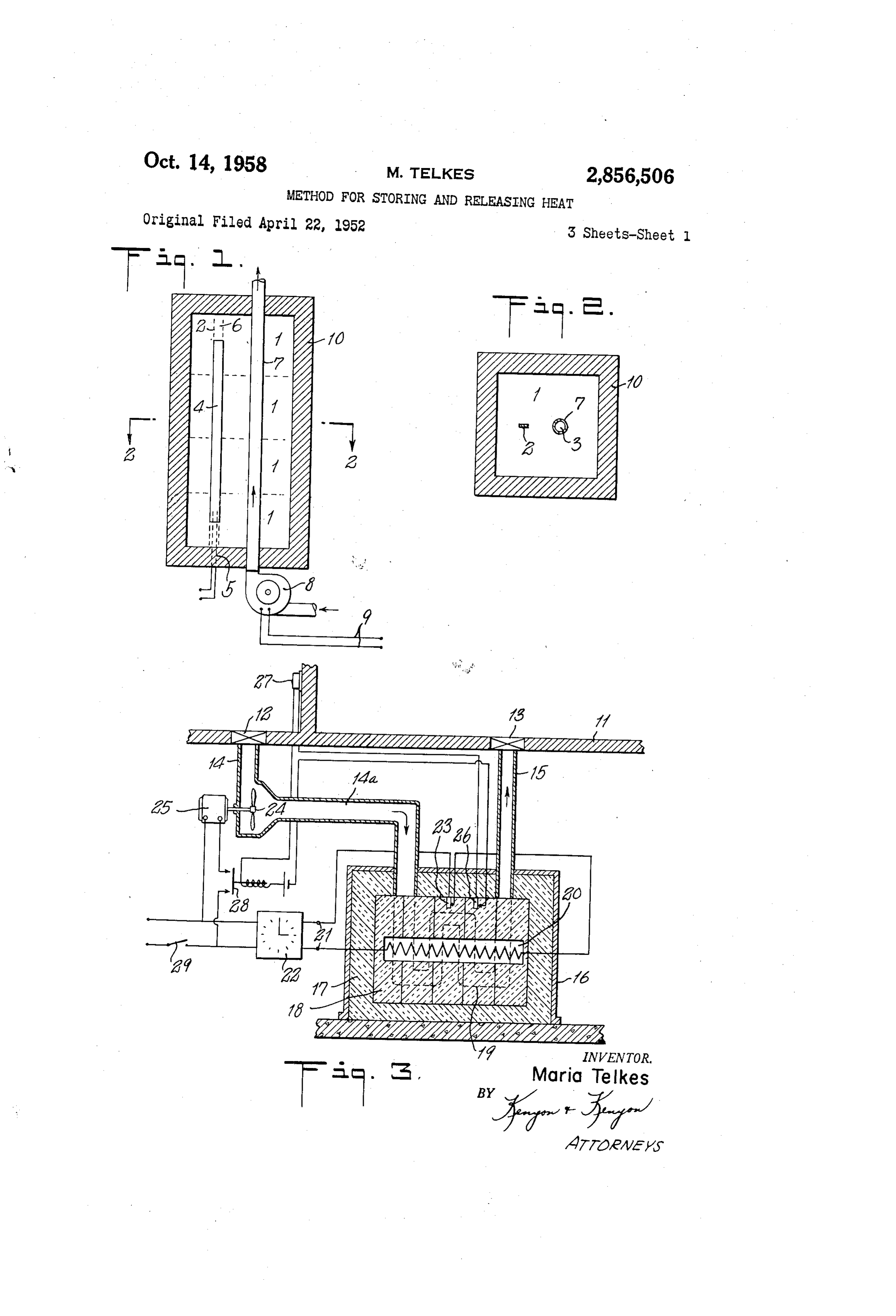
of steel and the like be heated to a high temperature and that the heat content of the material be thereafter used Fig. 1 is a sectional view of a simple form of appara while the temperature of the heat absorbing means goes tus embodying my invention comprising a series of down. Such devices of the prior art, however, are blocks of my material associated with heating and heat limited in their applicability by the fact that the only transfer means;
heat stored is sensible heat, which is a function of the Fig. 2 is a section along the line 2-2 in Fig. 1; specific heat of the material used. Since the specific Fig. 3 shows how my system can be incorporated in a heat of available materials is low, usually in the neigh space heating unit for utilizing off-peak electrical energy borhood of 0.2 B. t. u. per pound, the heat storage capac as the source of heat;
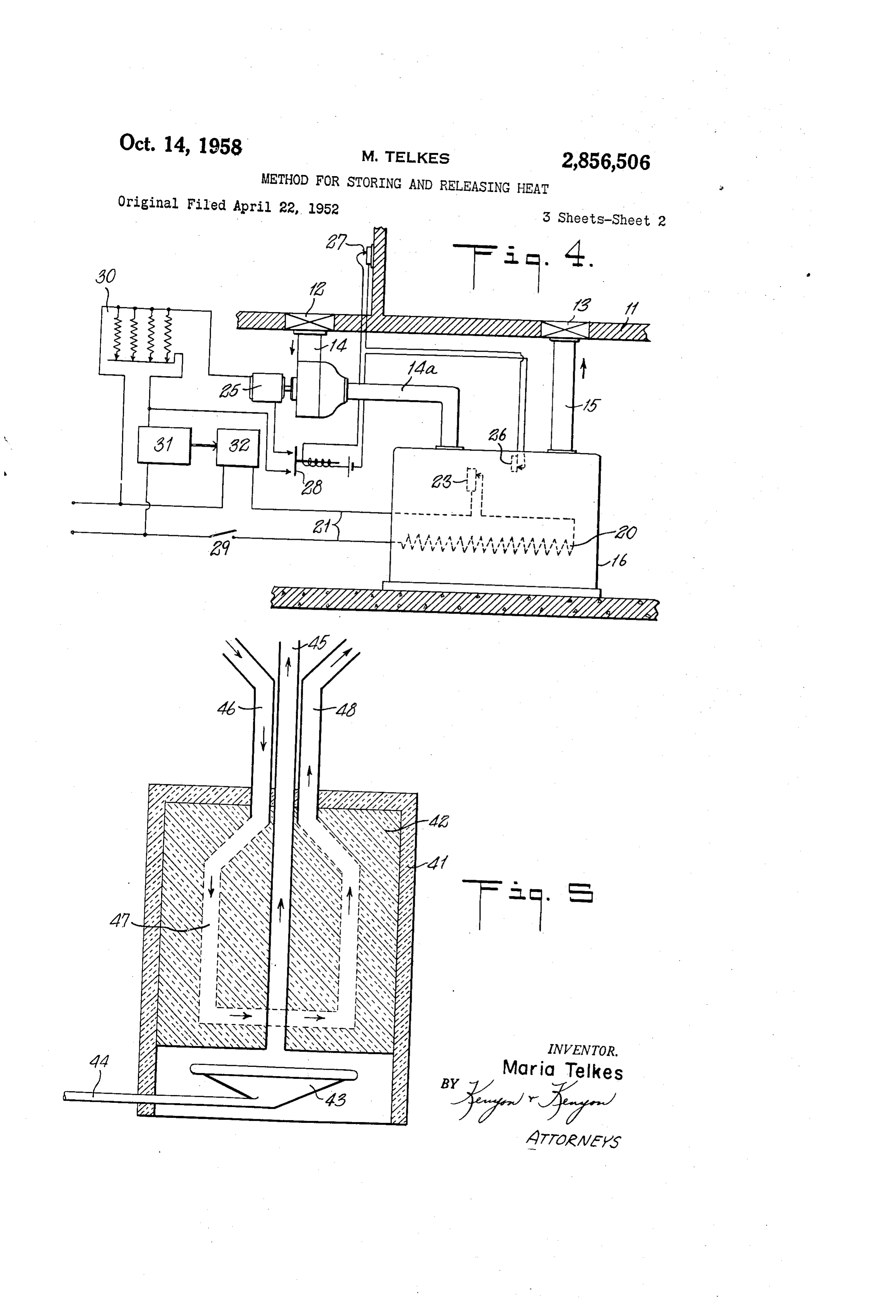
ity of such material between, for example, 200 and 500 50 Fig. 4 shows how my system can be connected to utilize F. is only 60 B. t. u. per pound. This renders such heat available electrical energy after other energy loads are storing means impractical for space heating purposes taken care of;
because of the large bulk necessary to provide storage Fig. 5 shows another form in which my system can be for large amounts of heat. More practical heat storage applied for utilizing gas or oil fuel instead of electrical systems have been devised in which heat of solution or 55 energy as the heating medium;
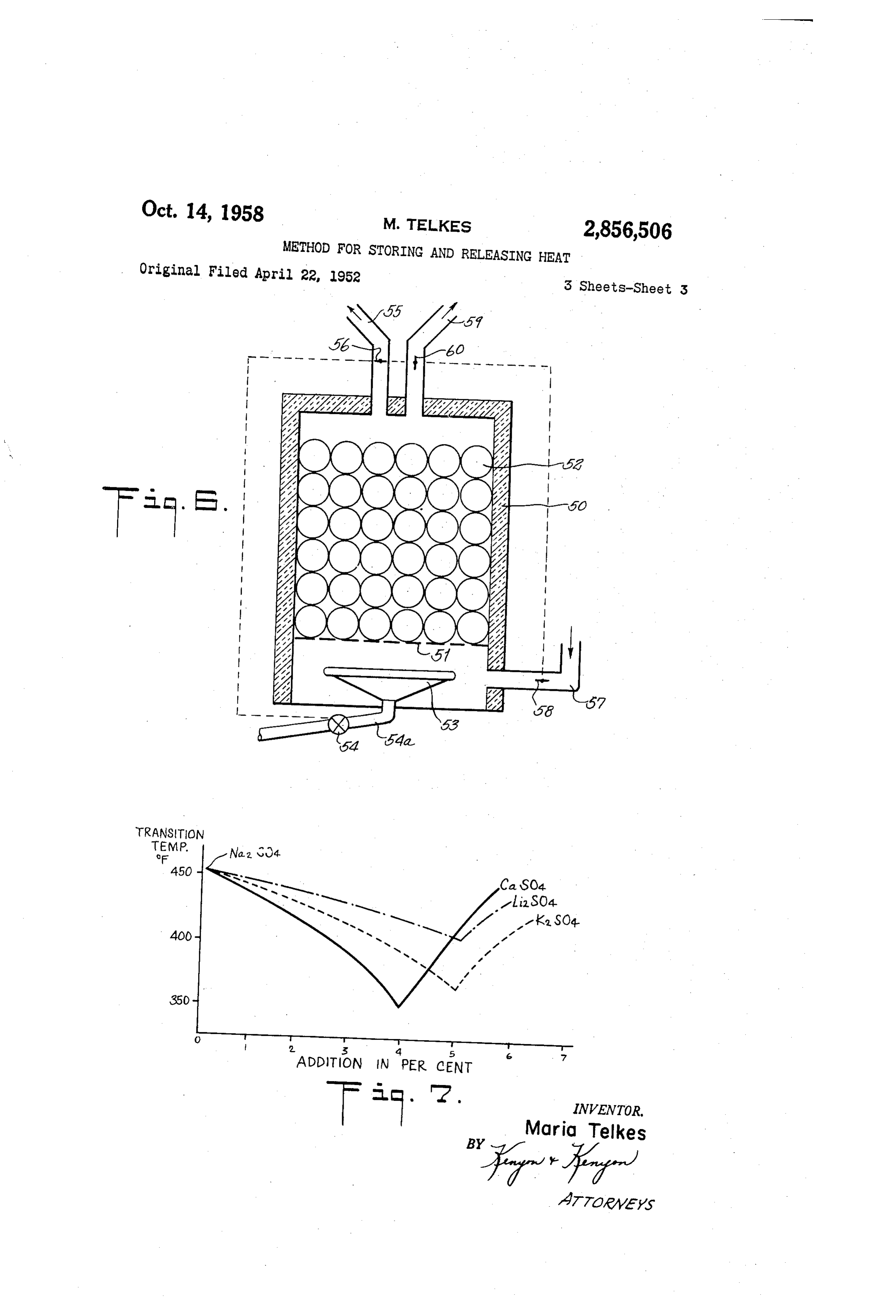
heat of fusion, or a combination of both, are utilized. Fig. 6 shows still another embodiment of my system; In such systems, a crystalline material having a large and amount of water of crystallization may be used, the Fig. 7 shows the effect of the admixture of small material being so applied and selected that, upon being amounts of other salts on the transition temperature of heated, the solid material melts or dissolves in its own 60 the anhydrous sodium sulfate.
water of crystallization, with the resulting storage of rela It will be recognized that Figs. 1 to 6, inclusive, are tively large quantities of heat in the form of latent heat largely diagrammatic and that the apparatus shown there of fusion and solution. The heat so stored can be re in may be varied without departing from the scope of my covered by permitting the material to recrystallize. Such invention, and also that other modifications of the appa systems are effective at relatively low temperatures, and 65 ratus, including those hereinafter discussed, will readily are best utilized either where a relatively low tempera suggest themselves upon the disclosure of my invention ture is desired, as in the so-called chemical hot water bot herein contained.
tles, or where large heating surface is available. In Figs. 1 and 2 the numerals 1 designate blocks of an It is the purpose of the present invention to provide a system, including apparatus and method, for storing heat 70 ferred tosodium hydrous sulfate, with or without the modifiers re above. These blocks are preferably prepared at a relatively high temperature, in the range of 300 to by mixing the powdered sulfate with 5 to 10% of water 550 F., for example, and yet to provide a heat storage and pressing the resulting mixture into the form desired,
Page 5
below and 50-75° F. above
When dried the resulting blocks are heated to slightly the heat storage material employed. the transition temperature of above 500 F. and cooled. They can be handled easily When the System is and do not readily chip or break. The blocks can also be as the source of heat, I prefer that it be peak” connected in such a way as to utilize "off electricity obtained by fusing the sodium sulfate (with or without the 5 the heat releasing part of the cycle may continuesotothat adjusted
additives) and casting it in molds. However, the high operated until the heat storage material reaches even melting point of the sodium sulfate and the brittleness of the cast product makes this method of producing the lower Fig.
temperatures, such as for example 200 F.
3 shows one method of installing my system for blocks less desirable. While the blocks prepared by my preferred method are non-dusting, I can, as a precaution 0 used as the onlyWhen space heating.
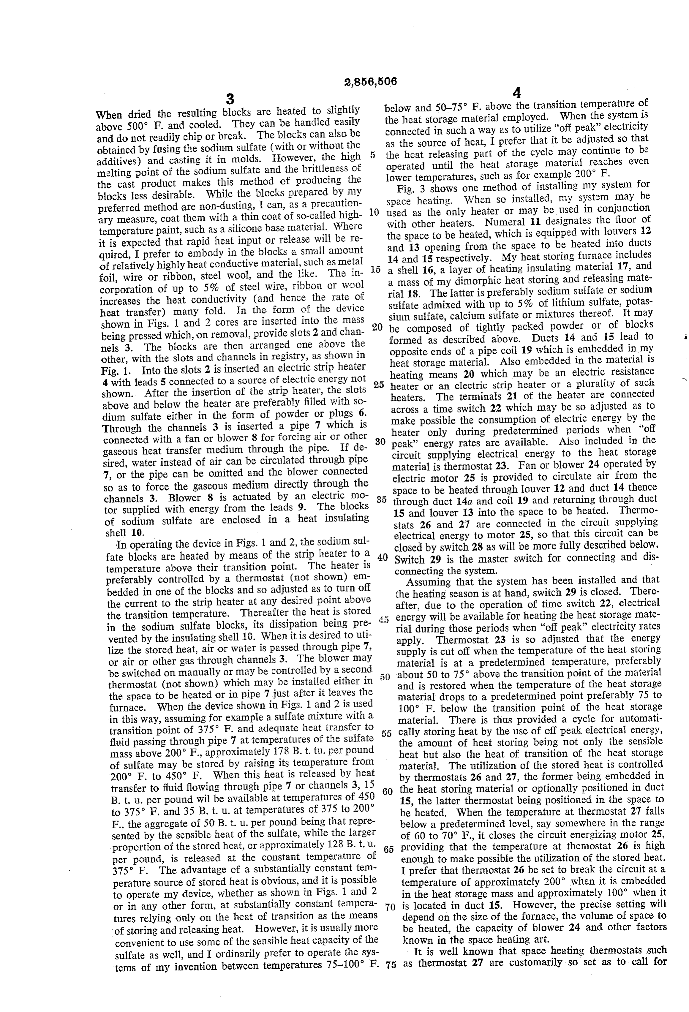
heater so installed, my system may be or may be used in conjunction ary measure, coat them with a thin coat of so-called high with other heaters. Numeral temperature paint, such as a silicone base material. Where the space to be heated, which is11equipped designates the floor of with louvers 12 it is expected that rapid heat input or release will be re and 13 opening from the space to be heated into ducts quired, I prefer to embody in the blocks a small amount of relatively highly heat conductive material, such as metal 5 14 and 15 respectively. My heat storing furnace includes a shell 16, a layer of heating insulating material 17, and foil, wire or ribbon, steel wool, and the like. The in a mass of my dimorphic heat storing and releasing mate corporation of up to 5% of steel wire, ribbon or Wool increases the heat conductivity (and hence the rate of rial 18. The latter is preferably sodium sulfate or sodium sulfate admixed with up to 5% of lithium sulfate, potas heat transfer) many fold. In the form of the device shown in Figs. 1 and 2 cores are inserted into the mass 20 sium sulfate, calcium sulfate or mixtures thereof. It may be composed of tightly packed powder or of blocks being pressed which, on removal, provide slots 2 and chan formed as described above. Ducts 14 and 5 lead to nels 3. The blocks are then arranged one above the opposite ends of a pipe coil 19 which is embedded in my other, with the slots and channels in registry, as shown in heat storage material. Also embedded in the material is Fig. 1. Into the slots 2 is inserted an electric strip heater heating 4 with leads 5 connected to a source of electric energy not 25 heater ormeans an 20 which may be an electric resistance electric strip heater or a plurality of such shown. After the insertion of the strip heater, the slots heaters. The terminals 21 of the heater are connected above and below the heater are preferably filled with sc across a time switch 22 which may be so adjusted as to dium sulfate either in the form of powder or plugs 6. make possible the consumption of electric energy by the Through the channels 3 is inserted a pipe 7 which is heater only during predetermined periods when "off connected with a fan or blower 8 for forcing air or other 30 gaseous heat transfer medium through the pipe. If de peak' circuit energy rates are available. Also included in the
Supplying electrical energy to the heat storage sired, water instead of air can be circulated through pipe material is thermostat 23. Fan or blower 24 operated by 7, or the pipe can be omitted and the blower connected so as to force the gaseous medium directly through the electric motor 25 is provided to circulate air from the Space to be heated through louver 12 and duct 14 thence channels 3. Blower 8 is actuated by an electric mo 35 through duct 14a and coil 19 and returning through duct tor supplied with energy from the leads 9. The blocks 15 and louver 13 into the space to be heated. Thermo of sodium sulfate are enclosed in a heat insulating stats 26 and 27 are connected in the circuit supplying shell 10.
In operating the device in Figs. 1 and 2, the sodium sul electrical energy to motor 25, so that this circuit can be closed by switch 28 as will be more fully described below.
fate blocks are heated by means of the strip heater to a 40 Switch 29 is the master switch for connecting and dis temperature above their transition point. The heater is connecting the system.
preferably controlled by a thermostat (not shown) em ASSuming that the system has been installed and that bedded in one of the blocks and so adjusted as to turn off the heating season is at hand, switch 29 is closed. There the current to the strip heater at any desired point above after, due to the operation of time switch 22, electrical the transition temperature. Thereafter the heat is stored 4.5 energy will be available for heating the heat storage mate in the sodium sulfate blocks, its dissipation being pre rial during those periods when "off peak” electricity rates vented by the insulating shell 10. When it is desired to uti apply. Thermostat 23 is so adjusted that the energy lize the stored heat, air or water is passed through pipe 7, Supply is cut off when the temperature of the heat storing or air or other gas through channels 3. The blower may material is at a predetermined temperature, preferably be switched on manually or may be controlled by a second about 50 to 75° above the transition point of the material thermostat (not shown) which may be installed either in and is restored when the temperature of the heat storage the space to be heated or in pipe 7 just after it leaves the material drops to a predetermined point preferably 75 to furnace. When the device shown in Figs. 1 and 2 is used 100 F. below the transition point of the heat storage in this way, assuming for example a sulfate mixture with a material. There is thus provided a cycle for automati transition point of 375 F. and adequate heat transfer to 55 cally storing heat by the use of off peak electrical energy, fluid passing through pipe 7 at temperatures of the sulfate the amount of heat storing being not only the sensible mass above 200 F., approximately 178 B. t. tu. per pound heat but also the heat of transition of the heat storage of sulfate may be stored by raising its temperature from material. The utilization of the stored heat is controlled 200 F. to 450 F. When this heat is released by heat by thermostats 26 and 27, the former being embedded in transfer to fluid flowing through pipe 7 or channels 3, 15 60 the heat storing material or optionally positioned in duct B. t. i. per pound will be available at temperatures of 450 15, the latter thermostat being positioned in the space to to 375 F. and 35 B. t. u. at temperatures of 375 to 200° be heated. When the temperature at thermost at 27 falls F., the aggregate of 50 B. E. u. per pound being that repre below a predetermined level, say somewhere in the range sented by the sensible heat of the sulfate, while the larger of 60 to 70 F., it closes the circuit energizing motor 25, proportion of the stored heat, or approximately 128 B. t.u. 65 providing that the temperature at themostat 26 is high per pound, is released at the constant temperature of enough to make possible the utilization of the stored heat. 375 F. The advantage of a substantially constant tem I prefer that thermostat 26 be set to break the circuit at a perature source of stored heat is obvious, and it is possible temperature of approximately 200 when it is embedded to operate my device, whether as shown in Figs. and 2 in the heat storage mass and approximately 100° when it or in any other form, at substantially constant tempera 70 is located in duct 15. However, the precise setting will tures relying only on the heat of transition as the means depend on the size of the furnace, the volume of space to of storing and releasing heat. However, it is usually more be heated, the capacity of blower 24 and other factors convenient to use some of the sensible heat capacity of the known in the space heating art.
sulfate as well, and I ordinarily prefer to operate the sys It is well known that space heating thermostats such 'tems of my invention between temperatures 75-100 F. 75 as thermostat 27 are customarily so set as to call for
Page 6
maintaining a higher temperature during the day than at night. On the contrary, off peak energy rates usually material in accordance with my invention, which material again may be built of blocks manufactured as hereinabove apply during the night, and particularly between the hours described of 11:00 p.m. and 7:00 a.m. or thereabouts. It will be or may be in compact powdered form. Fuel is Supplied
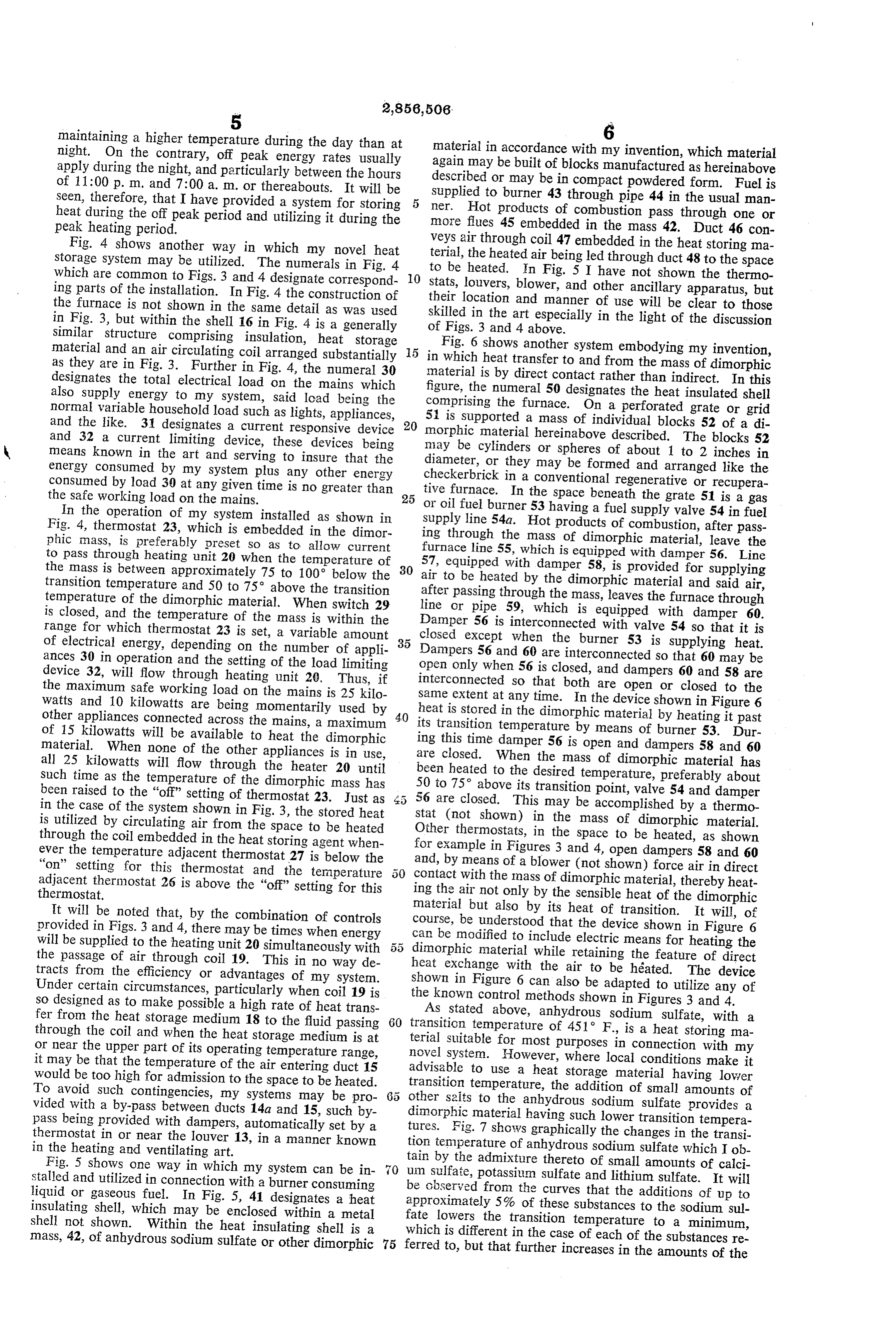
Seen, therefore, that I have provided a system for storing ner. Hot products to burner 43 through pipe 44 in the usual man heat during the off peak period and utilizing it during the more of combustion pass through one or peak heating period. flues 45 embedded in the mass 42. Duct 46 con Fig. 4 shows another way in which my novel heat terial, veys air through coil 47 embedded in the heat storing ma Storage System may be utilized. The numerals in Fig. 4 the heated air being led through duct 48 to the space which are common to Figs. 3 and 4 designate correspond 10 to be heated. In Fig. 5 I have not shown the thermo Stats, louvers, blower, and other ancillary apparatus, but ing parts of the installation. In Fig. 4 the construction of their location and manner of use will be clear to those the furnace is not shown in the same detail as was used in Fig. 3, but within the shell 16 in Fig. 4 is a generally of skilled in the art especially in the light of the discussion similar structure comprising insulation, heat storage Figs. 3 and 4 above.
material and an air circulating coil arranged substantially 5 Fig. 6 shows another system embodying my invention, as they are in Fig. 3. Further in Fig. 4, the numeral 30 in which heat transfer to and from the mass of dimorphic material is by direct contact rather than indirect. In this designates the total electrical load on the mains which figure, the numeral 50 designates the heat insulated shell also supply energy to my system, said load being the comprising the furnace. On a perforated grate or grid normal variable household load such as lights, appliances, 51 is Supported a mass of individual blocks 52 of a di and the like. 31 designates a current responsive device morphic
material hereinabove described. The blocks 52 and 32 a current limiting device, these devices being may be cylinders or spheres of about 1 to 2 inches in means known in the art and serving to insure that the diameter, or they may be formed and arranged like the energy consumed by my system plus any other energy consumed by load 30 at any given time is no greater than tive furnace. inInathe checkerbrick conventional regenerative or recupera space beneath the grate 51 is a gas the safe working load on the mains. 25
In the operation of my system installed as shown in or oil fuel burner 53 having a fuel supply valve 54 in fuel Fig. 4, thermost at 23, which is embedded in the dimor ing Supply line 54a. Hot products of combustion, after pass phic mass, is preferably preset so as to allow current through the mass of dimorphic material, leave the to pass through heating unit 20 when the temperature of furnace line 55, which is equipped with damper 56. Line the mass is between approximately 75 to 100 below the 30 air 57, equipped with damper 58, is provided for supplying transition temperature and 50 to 75 above the transition to be heated by the dimorphic material and said air, temperature of the dimorphic material. When switch 29 line after passing through the mass, leaves the furnace through is closed, and the temperature of the mass is within the or pipe 59, which is equipped with damper 60. range for which thermostat 23 is set, a variable amount closed Damper 56 is interconnected with valve 54 so that it is of electrical energy, depending on the number of appli 35 Dampersexcept when the burner 53 is supplying heat. 56 and 60 are interconnected so that 60 may be ances 30 in operation and the setting of the load limiting open only when 56 is closed, and dampers 60 and 58 are device 32, will flow through heating unit 20. Thus, if interconnected so that both are open or closed to the the maximum safe working load on the mains is 25 kilo same extent at any time. In the device shown in Figure 6 Watts and 10 kilowatts are being momentarily used by heat is stored in the dimorphic material by heating it past other appliances connected across the mains, a maximum 40 its transition temperature by means of burner 53. Dur of 15 kilowatts will be available to heat the dimorphic ing this time damper material. When none of the other appliances is in use, are closed. When the56mass is open and dampers 58 and 60 of dimorphic material has all 25 kilowatts will flow through the heater 20 until been
Such time as the temperature of the dimorphic mass has 50 to heated to the desired temperature, preferably about been raised to the “off” setting of thermostat 23. Just as 56 are75° above its transition point, valve 54 and damper closed. This may be accomplished by a thermo in the case of the system shown in Fig. 3, the stored heat stat is utilized by circulating air from the space to be heated Other(not shown) in the mass of dimorphic material. thermostats, in the space to be heated, as shown through the coil embedded in the heat storing agent when for ever the temperature adjacent thermostat 27 is below the and,example in Figures 3 and 4, open dampers 58 and 60 by means of a blower (not shown) force air in direct "on' setting for this thermostat and the temperature : contact with the mass of dimorphic material, thereby heat adjacent thermostat 26 is above the “off” setting for this ing the air thermostat. not only by the sensible heat of the dimorphic material
It will be noted that, by the combination of controls course, be understood but also by its heat of transition. It will, of provided in Figs. 3 and 4, there may be times when energy can that the device shown in Figure 6 will be supplied to the heating unit 20 simultaneously with 55 dimorphic be modified to include electric means for heating the the passage of air through coil 19. This in no way de heat exchange material while retaining the feature of direct tracts from the efficiency or advantages of my system. shown in Figurewith the air to be heated. The device Under certain circumstances, particularly when coil 19 is the known control6 methods can also be adapted to utilize any of shown in Figures 3 and 4.
so designed as to make possible a high rate of heat trans fer from the heat storage medium 18 to the fluid passing 60 transition temperature of 451 F.,sodium
AS stated above, anhydrous sulfate, with a is a heat storing ma through the coil and when the heat storage medium is at terial suitable for most purposes in connection with my or near the upper part of its operating temperature range, novel System. However, where local conditions make it it may be that the temperature of the air entering duct 15 advisable to use a heat storage material having lower would be too high for admission to the space to be heated. transition temperature, the addition of small amounts of To avoid Such contingencies, my systems may be pro other salts to the anhydrous sodium sulfate provides a vided with a by-pass between ducts 14a and 15, such by dimorphic material having such lower transition tempera pass being provided with dampers, automatically set by a tures. Fig. 7 shows graphically the changes in the transi. thermostat in or near the louver 13, in a manner known tion temperature of anhydrous sodium sulfate which I ob in the heating and ventilating art.
Fig. 5 shows one way in which my system can be in tain by the admixture thereto of small amounts of calci stalled and utilized in connection with a burner consuming be um sulfate, potassium sulfate and lithium sulfate. It will liquid or gaseous fuel. In Fig. 5, 41 designates a heat observed from the curves that the additions of up to insulating shell, which may be enclosed within a metal fate approximately 5% of these substances to the sodium sul shell not shown. Within the heat insulating shell is a whichlowers the transition temperature to a minimum, is different in the case of each of the substances re mass, 42, of anhydrous sodium sulfate or other dimorphic 75 ferred to, but that further increases in the amounts of the
Page 7
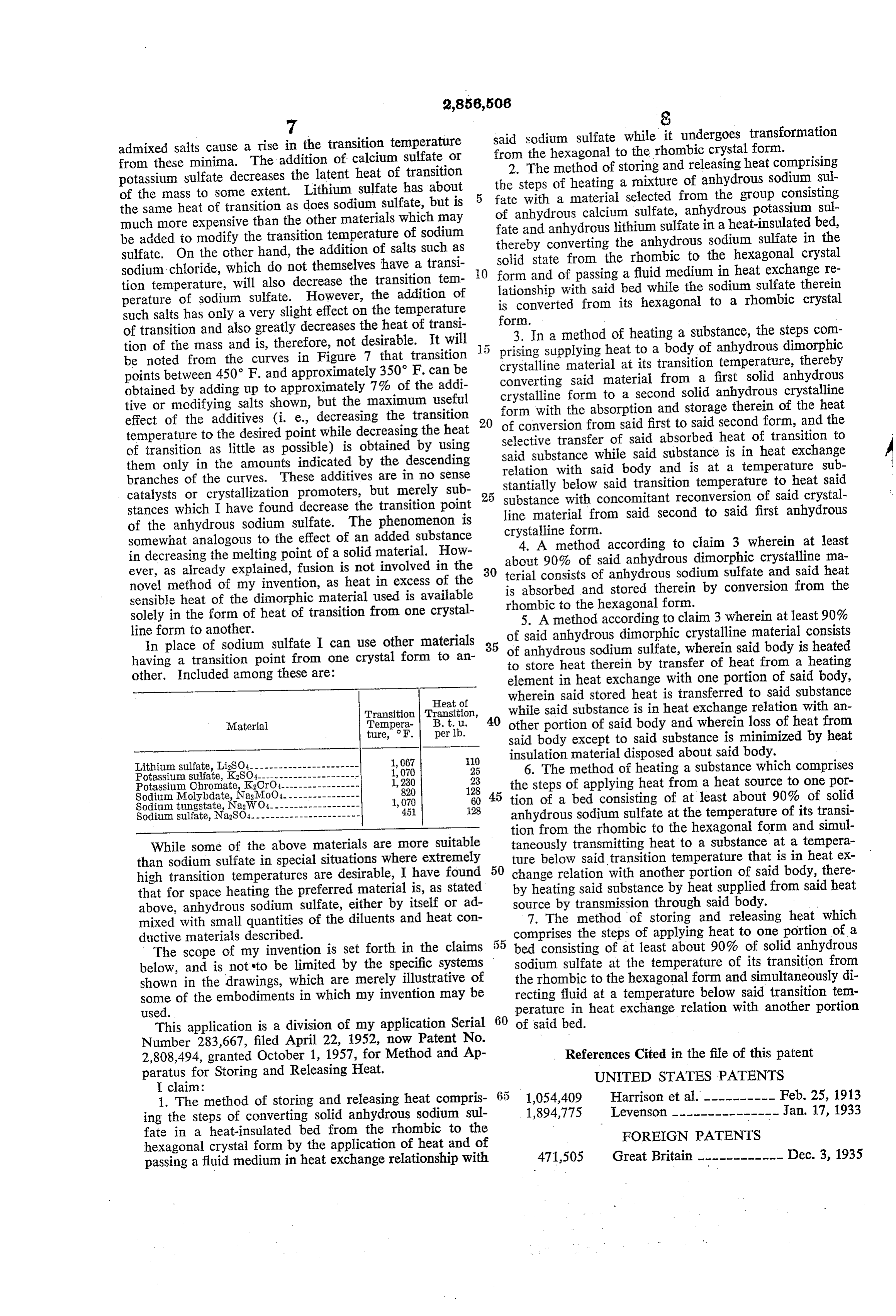
admixed salts cause a rise in the transition temperature said sodium sulfate while it undergoes transformation from these minima. The addition of calcium sulfate or from the hexagonal to the rhombic crystal form. 2. The method of storing and releasing heat comprising potassium sulfate decreases the latent heat of transition the steps of heating a mixture of anhydrous sodium Sul of the mass to some extent. Lithium sulfate has about fate with a material selected from the group consisting the same heat of transition as does sodium sulfate, but is of anhydrous calcium sulfate, anhydrous potassium Sul much more expensive than the other materials which may fate and anhydrous lithium sulfate in a heat-insulated bed, be added to modify the transition temperature of sodium thereby converting the anhydrous sodium sulfate in the sulfate. On the other hand, the addition of salts such as solid state from the rhombic to the hexagonal crystal sodium chloride, which do not themselves have a transi O form and of passing a fluid medium in heat eXchange re tion temperature, will also decrease the transition tem perature of sodium sulfate. However, the addition of lationship with said bed while the sodium sulfate therein is converted from its hexagonal to a rhombic crystal such salts has only a very slight effect on the temperature of transition and also greatly decreases the heat of transi form. 3. In a method of heating a substance, the steps com tion of the mass and is, therefore, not desirable. It will prising supplying heat to a body of anhydrous dimorphic be noted from the curves in Figure 7 that transition crystalline material at its transition temperature, thereby points between 450° F. and approximately 350 F. can be converting said material from a first solid anhydrous obtained by adding up to approximately 7% of the addi crystalline form to a second solid anhydrous crystalline tive or modifying salts shown, but the maximum useful form with the absorption and storage therein of the heat effect of the additives (i. e., decreasing the transition of conversion from said first to said second form, and the temperature to the desired point while decreasing the heat selective transfer of said absorbed heat of transition to of transition as little as possible) is obtained by using said substance while said substance is in heat exchange them only in the amounts indicated by the descending relation with said body and is at a temperature Sub branches of the curves. These additives are in no sense catalysts or crystallization promoters, but merely sub 25 substance below stantially with said transition temperature to heat said concomitant reconversion of said crystal stances which I have found decrease the transition point line material from said second to said first anhydrous of the anhydrous sodium sulfate. The phenomenon is crystalline form.
somewhat analogous to the effect of an added substance 4. A method according to claim 3 wherein at least in decreasing the melting point of a solid material. How about 90% of said anhydrous dimorphic crystalline ma ever, as already explained, fusion is not involved in the 30 terial consists of anhydrous sodium sulfate and said heat novel method of my invention, as heat in excess of the is absorbed and stored therein by conversion from the sensible heat of the dimorphic material used is available rhombic to the hexagonal form. solely in the form of heat of transition from one crystal 5. A method according to claim 3 wherein at least 90% line form to another. of said anhydrous dimorphic crystalline material consists In place of sodium sulfate I can use other materials 35 anhydrous sodium sulfate, wherein said body is heated having a transition point from one crystal form to an of to store heat therein by transfer of heat from a heating other. Included among these are: element in heat exchange with one portion of said body, Heat of wherein said stored heat is transferred to said substance
Transition Transition, 40 while said substance is in heat exchange relation with an
ture, F. per lb.
other portion of said body and wherein loss of heat from said body except to said substance is minimized by heat insulation material disposed about said body.
Potassium sulfate, K2SO4--------
25 6. The method of heating a substance which comprises
Potassium Chromate, K2CrO4
Sodium Molybdate, Na2MoC)
23 the steps of applying heat from a heat source to one por 28 45 tion of a bed consisting of at least about 90% of solid
Sodium tungstate, NaWO4-- 1,070 60
Sodium sulfate, Na2SO4----------------------- 45 28 anhydrous sodium sulfate at the temperature of its transi tion from the rhombic to the hexagonal form and simul
While some of the above materials are more suitable taneously transmitting heat to a substance at a tempera than sodium sulfate in special situations where extremely 50 ture below said transition temperature that is in heat ex high transition temperatures are desirable, I have found change relation with another portion of said body, there that for space heating the preferred material is, as stated by heating said substance by heat supplied from said heat above, anhydrous sodium sulfate, either by itself or ad Source by transmission through said body. mixed with small quantities of the diluents and heat con 7. The method of storing and releasing heat which ductive materials described. comprises the steps of applying heat to one portion of a The scope of my invention is set forth in the claims bed consisting of at least about 90% of solid anhydrous below, and is not to be limited by the specific systems Sodium sulfate at the temperature of its transition from shown in the drawings, which are merely illustrative of the rhombic to the hexagonal form and simultaneously di some of the embodiments in which my invention may be recting fluid at a temperature below said transition tem used. perature in heat exchange relation with another portion This application is a division of my application Serial 60 of said bed.
Number 283,667, filed April 22, 1952, now Patent No.
2,808,494, granted October 1, 1957, for Method and Ap References Cited in the file of this patent paratus for Storing and Releasing Heat. UNITED STATES PATENTS
I claim:
1. The method of storing and releasing heat compris 1,054,409 Harrison et al.---------- Feb. 25, 1913 ing the steps of converting solid anhydrous sodium sul 1,894,775 Levenson --------------- Jan. 17, 1933 fate in a heat-insulated bed from the rhombic to the FOREIGN PATENTS hexagonal crystal form by the application of heat and of passing a fluid medium in heat exchange relationship with 471,505 Great Britain ------------ Dec. 3, 1935
Provenance
- Collection
- Cited prior art
- Original PDF
- patentimages.storage.googleapis.com →
- Filed
- 1956-12-03
- Pages
- 7
- Method
- pdftotext (the PDF's own text layer) + pdftoppm 300dpi page scans
- Source
- Google Patents bibliographic record
- Granted
- 1958-10-14
- Inventors
- Telkes Maria
- Transcribed from
- patentimages.storage.googleapis.com →