patent · US6364002B1
Heat storage apparatus
2 April 2002
Page 1 — bibliographic record
(12) United States Patent (10) Patent No.: US 6,364,002 B1 Hennig et al. (45) Date of Patent: Apr. 2, 2002
(54) HEAT STORAGE APPARATUS 3,412,728 A 11/1968 Thomason ................... 165/10 4,091,622 A 5/1978 Marchesi .................... 165/9.1 (75) Inventors: Christoph Hennig, Schwabach; Jochen 4,139,055 A 2/1979 Thomason et al. Scharrer, Neumarkt; Bernd Schulz, 4,187,831. A 2/1980 Eubank ...................... 165/164 Ilsfeld, all of (DE) 4,237,963 A 12/1980 Girard ......................... 165/45
(73) Assignee: IVT Installations und 4,479,487. A 10/1984 Migdal Verbindungstechnik GmbH & Co. 6,158,499 A 12/2000 Rhodes et al. ................ 165/10 KG, Schwabach (DE)
FOREIGN PATENT DOCUMENTS
(*) Notice: Subject to any disclaimer, the term of this patent is extended or adjusted under 35 DE 93 15785.1 2/1994
U.S.C. 154(b) by 0 days. DE 94 18656.1 5/1995
(21) Appl. No.: 09/622,934 WO WO97/41395 11/1997 (22) PCT Filed: Feb. 13, 1999 * cited by examiner
S371 Date: Aug. 24, 2000 Primary Examiner-Henry Bennett
ASSistant Examiner Terrell McKinnon
S 102(e) Date: Aug. 24, 2000 (74) Attorney, Agent, or Firm Sughrue Mion, PLLC (87) PCT Pub. No.: WO99/43988 (57) ABSTRACT PCT Pub. Date: Sep. 2, 1999 Aheat Storage apparatus for a temperature range of about 10 (30) Foreign Application Priority Data to 95 degrees Celsius, especially for Solar installations, heat Feb. 24, 1998 (DE) ......................................... loss pumps, operationboilers or theheating of a room like andinstallation for extraction of heat and/or for the an installa (51) Int. Cl. ................................................ F28D 17/00 tion for water for use, consists of a low-temperature latent (52) U.S. Cl. ............................... 165/10; 165/DIG. 902; heat storage device and a downstream water reservoir. In 126/641; 126/643 that case, the fresh water feed for the installation for water (58) Field of Search ......................... 165/10, 48.1, 236, for use runs, for preheating, through the low-temperature 165/DIG. 902, 641–643; 126/400, 569; latent heat Storage device before entry into the water reser 62/434, 59 voir and the return of the heat eXchanger runs, for further cooling down of the return flow to the lowest possible (56) References Cited temperature level, through the low-temperature latent heat
Storage device after exit from the water reservoir.
2,396,338 A 3/1946 Newton ....................... 165/10 9 Claims, 2 Drawing Sheets
Page 2
Drawing sheet — no readable text.
Page 3
Drawing sheet — no readable text.
Page 4
HEAT STORAGE APPARATUS However, heat is fed to the heat Storage apparatus 1 from a heat Source, for example a Solar collector installation 5.
BACKGROUND OF THE INVENTION The collector feed 51 is connected with the inlet of the second heal exchanger 32 of the water reservoir 3 and the
The present invention relates to a heat Storage apparatus collector return 52 is connected with the outlet of the second for a temperature range of 10 to 95 degrees Celsius. heat eXchanger 22 in the LT latent heat Storage means 2. This The heat Storage apparatus of the kind with a water means that the Solar-heated heat carrier liquid of the collec reservoir and at least one heat eXchanger Serve preferably for tor circuit initially delivers its heat in the water reservoir 3 the Storage of the heat of Solar installations and heat pumps in a medium temperature range of 20 to 60 degrees Celsius and for the extraction of heat for operation of a room heating and then Still flows through the LT latent heat Storage means installation and/or an installation for water for use. These 2, where it delivers its residual heat at a low temperature heat Storage apparatus are, however, Subject to the disad level of about 15 to 25 degrees Celsius. The LT latent heat Vantage that the return flow temperature is too high for, in Storage means 2 and thus the fresh water flowing through the particular, a Solar installation and the collector field thereby first heat heat eXchanger 21 are thereby now heated up. A latent
Storage means 2 with a high Storage capacity is accord has to operate with poor efficiency. 15 ingly necessary at this place, because the residual heat SUMMARY OF THE INVENTION during the day arises only in a limited time span, whereas the time span in which fresh water must be preheated is very
The invention therefore has the object of further devel much greater. Due to the LT latent heal Storage means 2 it oping a heat Storage apparatus So that the return flow to the is ensured that the Solar return flow is similarly disposed at Solar installation is reduced in its temperature as far as a very low temperature level, whereby the efficiency of the possible. Solar installation 5 is Substantially increased.
BRIEF DESCRIPTION OF THE DRAWINGS
The HT latent heat storage means 4 serves for possibly necessary reheating of the heat Storage apparatuS 1 by an
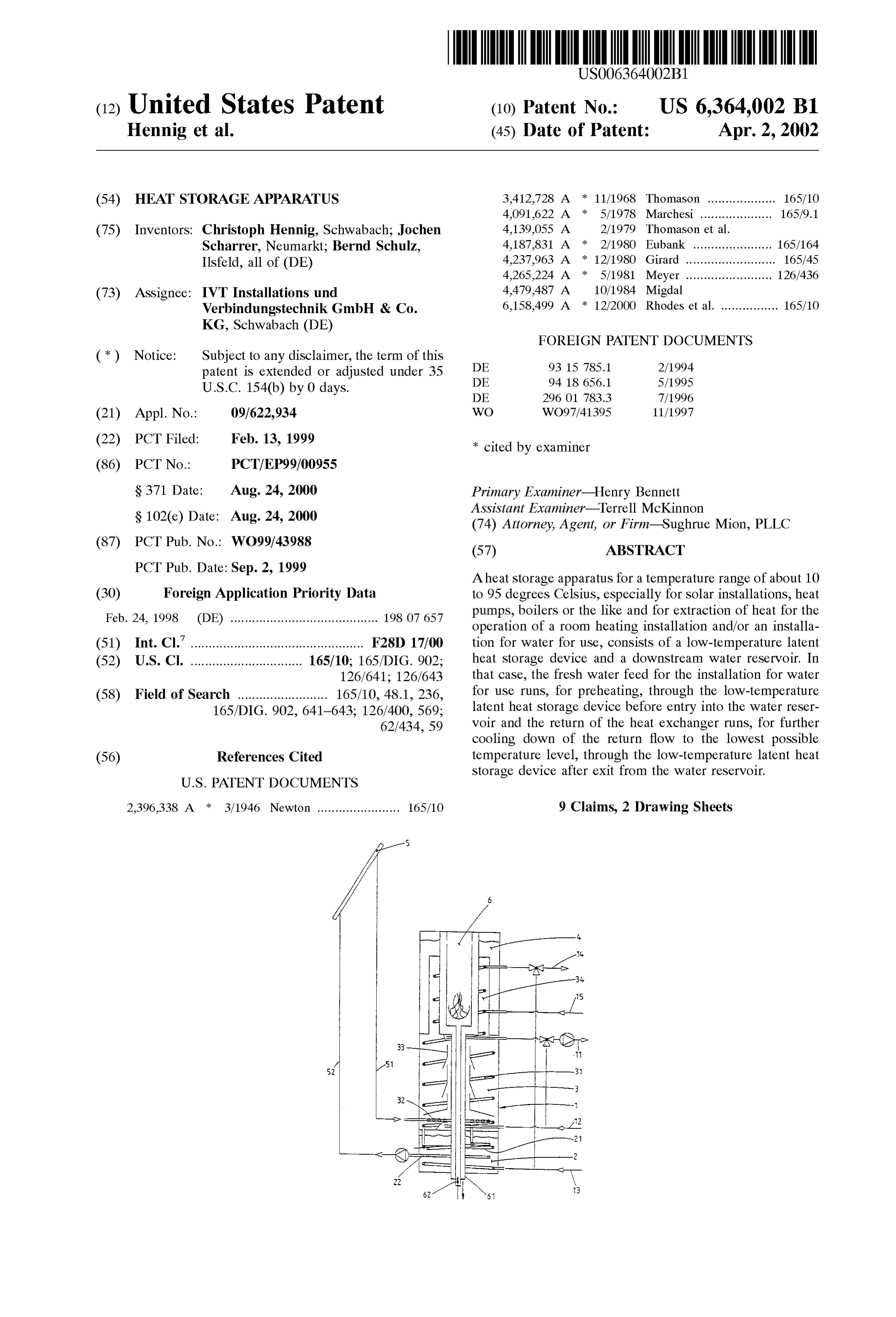
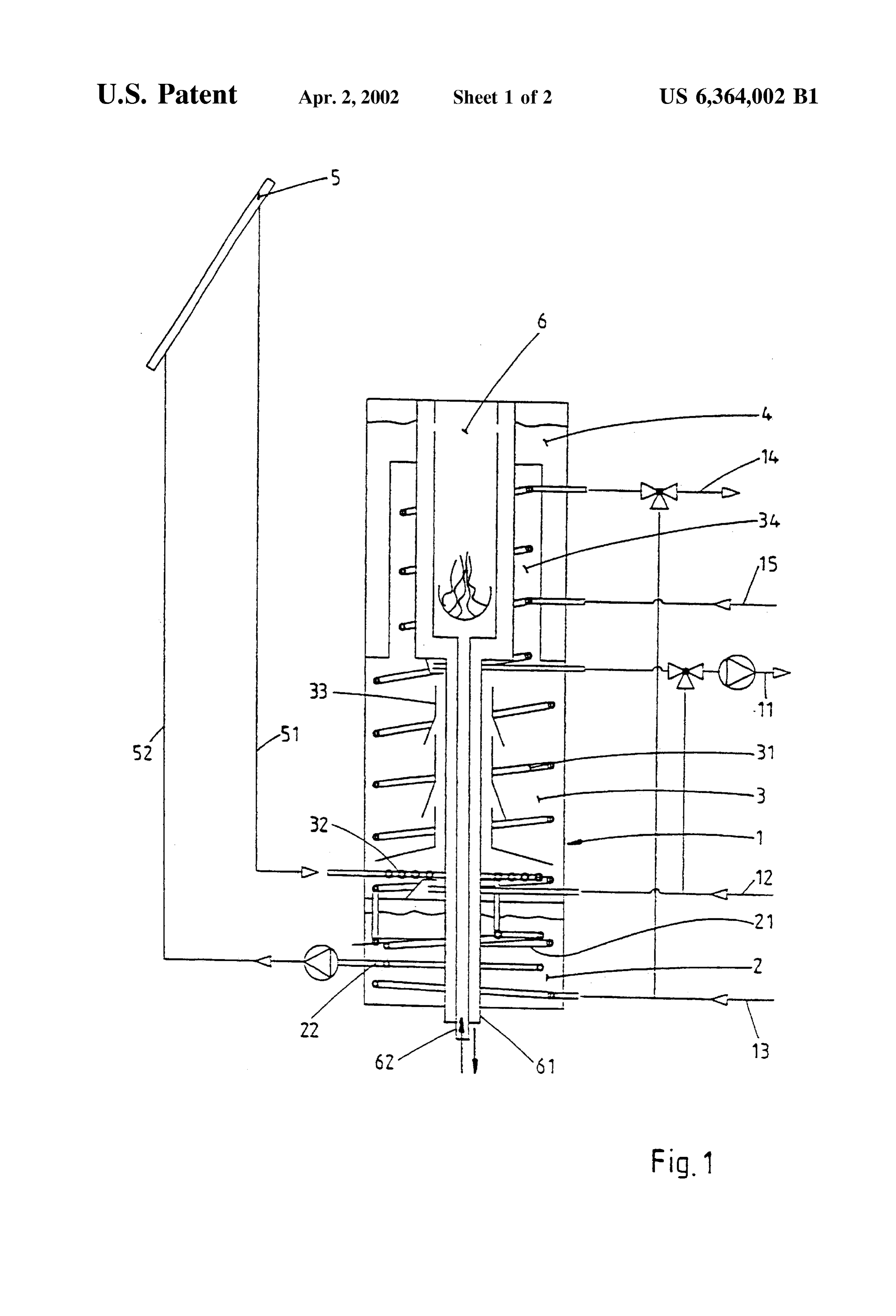
Embodiments of the invention are reproduced in the integrated boiler 6. In order to guarantee an energy-saving drawings, in which: 25 operation of the burner, this should have the Smallest pos FIG. 1 shows a vertical Section through the heat Storage burner Sible ignition phases (low "cycling”) with longest possible apparatus with integrated boiler and running times in order to achieve good efficiency and low noxious Substance emission. The HT latent heat Storage
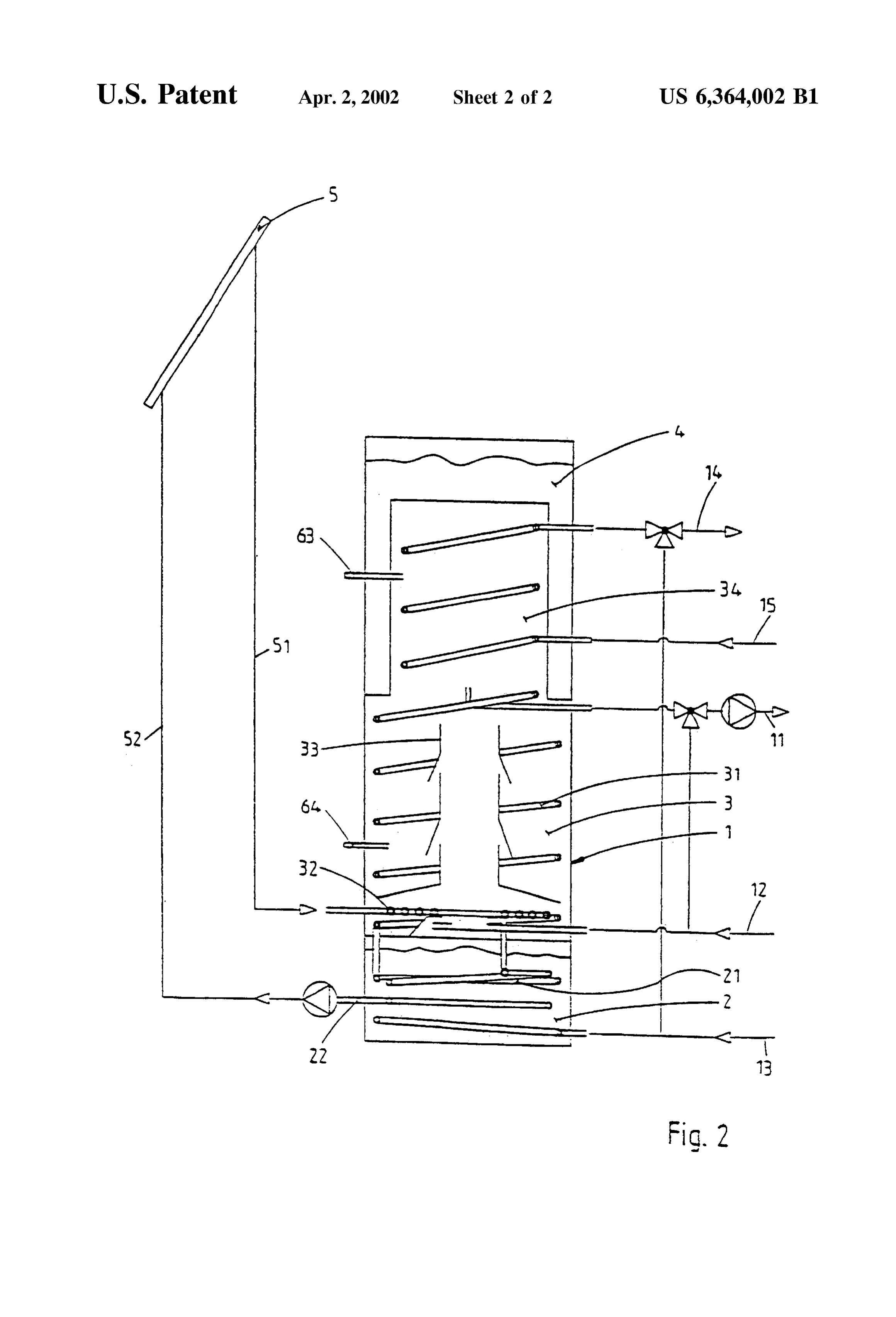
FIG. 2 shows a vertical Section through a heat Storage means 4 with a large heat capacity is particularly Suitable for apparatus with Separate boiler. that purpose. The heat can be stored therein in a temperature
DETAILED DESCRIPTION OF THE
range of 50 to 95 degrees Celsius.
INVENTION
In FIG. 1 there is illustrated a heat Storage apparatus 1 with a boiler 6 in plunger mode of construction, which is
Aheat Storage apparatus 1 can Store heat in a temperature integrated into the HT latent heat storage means 4. Fresh air range of 10 to 95 degrees Celsius. The heat can be made 35 is conducted to and exhaust gas conducted from the boiler 6 available by a solar installation 5, a heat pump or a boiler 6. by a double tube 61, 62. The double tube 61, 62 runs from It can then be extracted again at the heat Storage apparatus the boiler 6 into the HT latent heat storage means 4 through 1 for operation of a room heating installation 11, 12 and/or the into water reservoir 3 and the LT latent heat Storage means 2 the free atmosphere. In that case the exhaust gas flows a water-using installation 13, 14. The room heating instal through the Space, which is annular in cross-section, lation has, in known manner, a feed 11 and a return 12 and 40 between the two tubes 61, 62, whereas the fresh air flows in the installation for water for use has a fresh water duct 13, the inner tube 62 to the boiler 6. The cold fresh air in the tube a duct 14 for water for use to tapping points and a circulation 62 is therefore preheated by the hot exhaust gas. Moreover, duct 15. The water temperature is regulated by a three-way the exhaust gas delivers its heat in Succession firstly to the cock not only in the feed 11 of the room heating installation,
HT latent heat Storage means 4, then to the water reservoir but also in the duct 14 for water for use. 45 3 and finally to the LT latent heat Storage means 2, wherein The heat Storage apparatus 1 consists of a low if the temperature of 100 degrees Celsius is fallen below the temperature (LT) latent heat Storage means 2, a downstream Steam condenses and condensation heat is delivered water reservoir 3 and possibly also a further downstream ("calorific value technology’). high-temperature (HT) latent heat storage means 4, which The heat storage apparatus 1 illustrated in FIG. 1 with can also consist, in modular mode of construction, of 50 integrated boiler 6 in plunger mode of construction repre individual Separable units. A heat eXchanger 21 is disposed sents only one preferred form of embodiment. However, it is in the LT latent heat Storage means 2 and a heat eXchanger also possible, without further measures, to operate the heat 31 in the water reservoir 3. The two heat exchangers 21, 31 Storage apparatuS 1 with an adjacently disposed boiler, as is are hydraulically connected in Series and form a unit. The illustrated in FIG. 2. This has, however, the disadvantage Same applies in each case to a Second heat eXchanger 22 in 55 that the calorific value method cannot be realized with an the LT latent heat Storage means 2 and a heat eXchanger 32 adjacently disposed boiler or can be realized only with in the water reservoir 3. These two heat exchangers 22, 32 considerable technical outlay. The boiler is connected to the are also connected in Series and hydraulically form a unit. boiler feed connection 63 and to the boiler return connection The water reservoir 3 is formed as a layer store with guide 64.
plates 33, wherein the guide plates 33 assist temperature 60 The construction, which is reproduced in figS. 1 and 2, of stratification in the reservoir 3. the HT latent heat storage means 4, which surrounds the The fresh water duct 13 is connected with the first heat upper part 34 of the water reservoir 3 in the manner of a exchanger 21. The cold freshwater therefore runs through jacket, has the advantage that a constructive water-for-use the LT latent heat Storage means 2 and this would, if no feed priority circuit is given, as the upper water reservoir part 34 of heat were to take place, be cooled down to the low 65 is automatically heated by the boiler first of all and the temperature level of the fresh water of about 15 degrees heating feed 11 lies below in the relatively colder tempera Celsius. ture range.
Page 5
A further advantage of this construction consists in that with a water outlet duct, a Solar heat collector for heating a for the heat transfer from the upper water reservoir part 34 heat carrier liquid by Solar heating, a third heat eXchanger to the HT latent heat Storage means 4 a greater heat eXchange arranged in a lower part of the water reservoir and having area is available than would be the case, for example, in the inlet means connected with a liquid feed from the collector, case of a heating coil. and a fourth heat eXchanger arranged in the low-temperature latent heat Storage means to be in Series connection with the third heat eXchanger and having outlet means connected
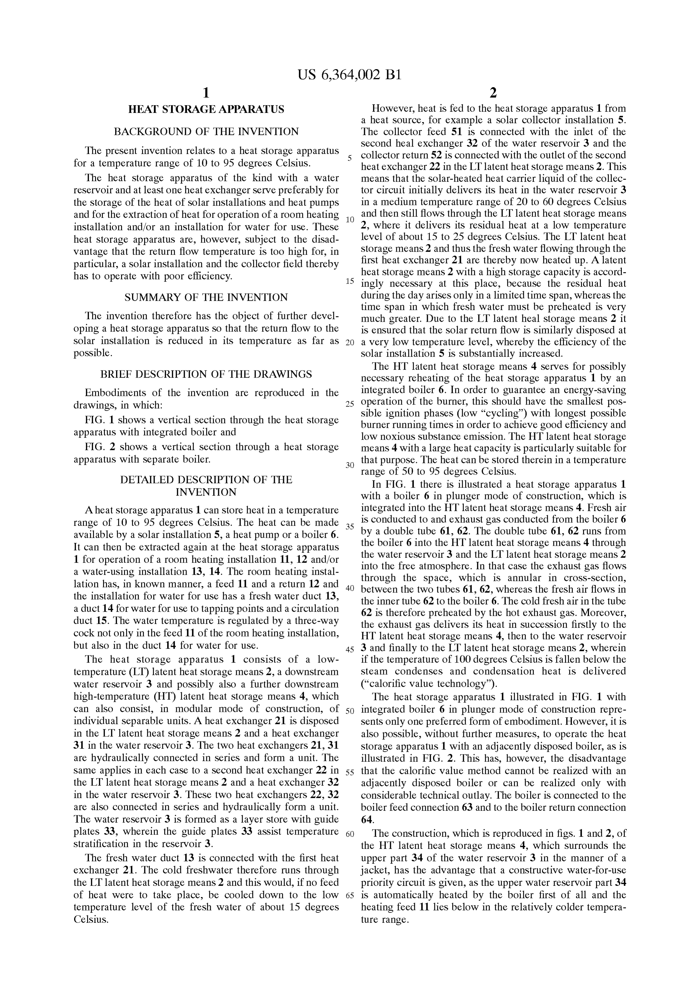
Reference Numeral List with a liquid return for the collector So that the carrier liquid heat storage apparatus can be cooled down in the low-temperature latent heat 1. heating feed Storage means before return to the collector. 12 heating return 2. The apparatus according to claim 1 wherein the water 13 resh water duct reservoir is constructed as a layer reservoir. 14 water-for-use duct 15 circulation duct 3. The apparatus according to claim 2 comprising guide 2 ow-temperature (LT) latent heat storage means 15 plates arranged in the reservoir to assist layering of water 2 heat exchanger flows into and out of the reservoir. 22 heat exchanger 4. The apparatus according to claim 1 comprising a boiler 3 water reservoir 3 heat exchanger with an exhaust gas heat eXchanger connected with the 32 heat exchanger low-temperature latent heat Storage means. 33 guide plate 5. The apparatus according to claim 1 comprising a boiler 34 upper water reservoir part 4 high-temperature (HT) latent heat storage means with an exhaust gas heat eXchanger connected with the water 5 solar collector installation reservoir.
5 collector feed 6. The apparatus according to claim 1 comprising a 52 collector return 6 boiler high-temperature latent heat Storage means downstream of 6 exhaust gas flue 25 the water reservoir.
resh water tube boiler feed 7. The apparatus according to claim 6 comprising a boiler 64 boiler return with an exhaust gas heat eXchanger integrated into the high-temperature latent heat Storage means.
What is claimed is:
8. The apparatus according to claim 7 comprising a first 1. A heat Storage apparatus for a heat temperature range tube arranged to conduct air to the boiler and a Second tube of Substantially 10 to 90° C., comprising a low-temperature Surrounding gas away the first tube and arranged to conduct exhaust from the boiler in a flow direction opposite to that latent heat Storage means, a water reservoir downstream of of the air, the first the low-temperature latent heat Storage means, a first heat water reservoir andand the second tubes extending through the low-temperature latent heat Storage eXchanger arranged in the low-temperature latent heat Stor 35 CS.
age means and having inlet means for connection with a 9. The apparatus according to claim 6, wherein the water feed duct So that water Supplied by the feed duct can be preheated in the low-temperature latent heat Storage high-temperature latent heat Storage means Surrounds an means, a Second heat eXchanger arranged to extend through upper part of the water reservoir.
the water reservoir and to be in Series connection with the first heat eXchanger and having outlet means for connection
Provenance
- Collection
- Patents citing this work
- Original assignee
- IVT Installations und Verbindungstechnik GmbH and Co KG
- Current assignee
- I V T Installations-Und Verbindungstechnik & Co KG GmbH
- Pages
- 5
- Method
- pdftotext (the PDF's own text layer) + pdftoppm 300dpi page scans
- Patent office record
- patents.google.com →
- Source
- Google Patents citing-documents table
- Inventors
- Christoph Hennig; Jochen Scharrer; Bernd Schulz; IVT Installations und Verbindungstechnik GmbH and Co KG
- Published
- 2002-04-02
- Transcribed from
- patentimages.storage.googleapis.com →