patent · US4091622
Combined day and night solar energy system
30 May 1978
Page 1 — bibliographic record
United States Patent (19) (11) 4,091,622 Marchesi 45 May 30, 1978 54 COMBINED DAY AND NIGHT SOLAR Attorney, Agent, or Firm-Clarence A. O'Brien; Harvey ENERGY SYSTEM B. Jacobson 76 Inventor: Carlo M. Marchesi, 31 Winter St., 57 ABS TRACT Saugus, Mass. 01906 A solar heat wave energy system having a solar energy 21 Appl. No.: 745,830 collector that collects energy from the sun to heat a boiler which in turn runs a steam turbine generator for 22 Filed: Nov. 29, 1976 generating electricity during the daytime. The system also has an assembly for generating electricity during
Related U.S. Application Data the nighttime, which assembly includes a storage struc ture disposed between the solar collector and the boiler.
abandoned.
of Ser. No. 597,820, Jul. 21, 1975, This storage structure includes a plurality of separate storage stacks, each housed underground and including 5ll Int. Cl’................................................ FO3G 7/02 a plurality of heat conductive pipes interdigitally ar 52 U.S.C. ........................................ 60/641; 60/659; ranged with a plurality of plates constructed from
twice-baked clay and arranged resting on a base formed 58) Field of Search .................. 60/641, 659; 126/270, from a similar clay as the plates. Solar energy is ab 126/271; 165/DIG. 4, 104 S, 9.1 sorbed by the collector and transferred to the storage structure by means of suitable piping for storage in the 56) References Cited twice-baked clay plates. When the stored heat is to be
later used, as in the nighttime or on overcast days, a switching device uncouples the collector from the stor 603,317 5/1898 Calver .................................. 126/270 age structure and couples the storage structure to the 608,755 8/1898 Cottle ................................... 126/270 boiler.
Primary Examiner-Allen M. Ostrager 8 Claims, 11 Drawing Figures
Page 2
Drawing sheet — no readable text.
Page 3
Drawing sheet — no readable text.
Page 4
Drawing sheet — no readable text.
Page 5
Drawing sheet — no readable text.
Page 6
These and other objects are achieved according to
COMBINED DAY AND NIGHT SOLAR ENERGY the present invention by providing a combined day and SYSTEM night energy system which receives energy from the
CROSS REFERENCE TO A RELATED sun and converts this energy into electrical or other APPLICATION useful energy in such a manner that the energy is avail able in both the daytime and the nighttime. More specif
This is a continuation-in-part of my copending appli ically, the system comprises a solar collector arranged cation Ser. No. 597,820, filed July 21, 1975 now aban for receiving the rays of the sun and concentrating such doned. rays in order to heat a pipe arrangement containing a 10 suitable heat transfer fluid. The system also comprises a
BACKGROUND OF THE INVENTION boiler coupled to the solar collector by the pipe ar 1. Field of the Invention rangement for converting the heat transferred to the This invention relates generally to a system for gener fluid contained in the pipe arrangement into steam, and ating electricity or other forms of energy by means of still further includes a steam actuated turbogenerator solar energy, and particularly to an improved storage 15 for generating electricity from energy imparted to the structure for storing the solar energy for subsequent use generator by the steam.
during the night or other times when the sun is not While the heat absorbed by the fluid contained in the available. pipe arrangement can advantageously be used directly 2. Description of the Prior Art to generate electricity, or other useful power, during There are many different forms of energy that one 20 periods of sunshine, the system also includes a heat can attempt to exploit, especially in view of the current storage unit according to the invention for permitting energy crisis which has changed the relative economies the system to generate power during the nighttime and of various energy sources. One of the sources of energy other periods when the sun's rays are blocked from the under investigation is solar energy. The drawback with 25 solar collector. Preferably, the heat storage unit forms the use of solar energy, however, is that it is only practi part of one assembly of the invention, which assembly also includes a generating unit and possibly a separate cal to use during the time that the sun is out, which time boiler, is only slightly more than 90% in those areas of the steam. ifThe such is required for generation of the requisite planet having the highest possible percentage of sun undergroundheat and storage unit is preferably contained can be formed as a group of separate shine, and in most inhabited areas of the planet is not 30 stacks, each comprising a plurality of plates constructed much more than 50%.
from twice-baked clay. Heat
In view of this relative low potential utilization of these plates by means of a plurality is transferred and stored in solar energy equipment, various proposals have been pipes of heat conductive interleaved between brought forth for providing a solar energy system with for transferring heat to the plates. the twice-baked clay plates a heat sink, or heat storage device, which permits the 35 The efficiency of the system of the present invention energy absorbed into the system from the sun to be stored for essentially continuous operation of the sys isable increased by the use of a solar collector that is mov and not fixed. More specifically, the collector as tem. Examples of such proposals can be found in U.S. sembly according to the invention advantageously in Pat. Nos: 2,933,885, issued Apr. 26, 1960, to E. K. Bene cludes two sequentially operated collectors, each in deket al.; 2,968,916, issued Jan. 24, 1961, to C. F. Taylor cluding its own winding, or zig-zag, piping arrange et al.; 3,029,596, issued Apr. 17, 1962, to R. J. Hanold et ment. The collectors are operated so that one collector al.; 3,780,262, issued Dec. 18, 1973, to R. L. Rudd; and is absorbing heat as it moves with the sun, while the
Other examples of heat storage units can be found in other collector is already absorbed sufficient heat to be delivering steam to the turbogenerator or generators.
my prior U.S. Pat. No. 3,678,919, issued July 25, 1972, 45 These together with other objects and advantages as well as in U.S. Pat. Nos: 3,299,945, issued Jan. 24, which will become subsequently apparent reside in the 1967, to R. E. Rice et al.; 3,301,251, issued Jan. 31, 1967, details of construction and operation as more fully here to R. A. F. Jackson; 3,381,113, issued Apr. 30, 1968, to inafter described and claimed, reference being had to J. K. Jacques et al.; and 3,464,486, issued Sept. 2, 1969, the accompanying drawings forming a part hereof, to R. E. Rice et al. 50 wherein like numerals refer to like parts throughout. SUMMARY OF THE INVENTION BRIEF DESCRIPTION OF THE DRAWINGS
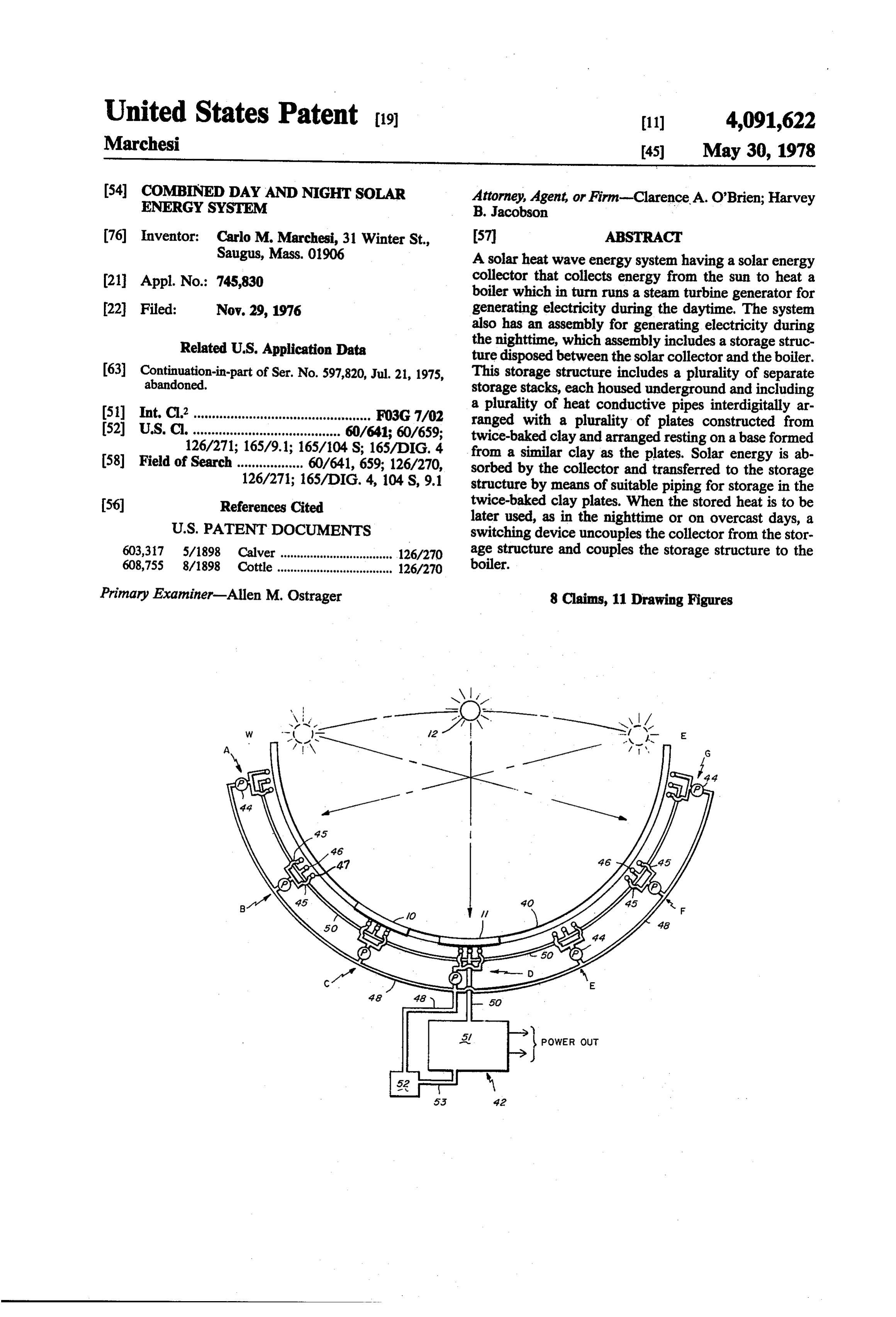
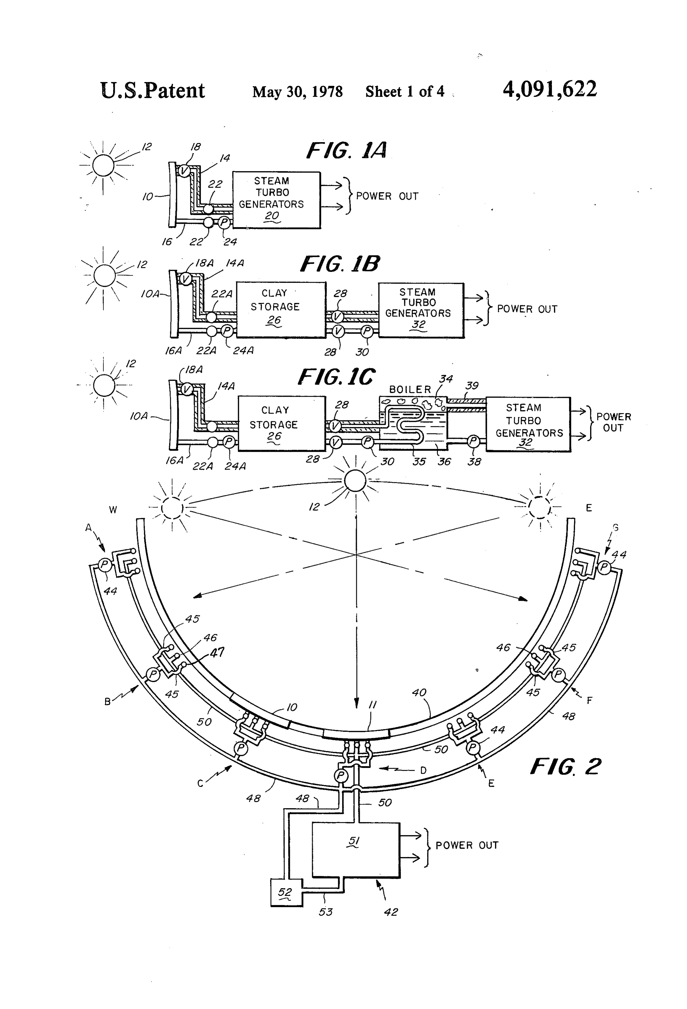
It is an object of the present invention to provide an FIG. 1A is a schematic block diagram showing one improved system for combined day and night usage for possible embodiment of that portion of the system of the generating electricity or other forms of energy from 55 present invention which can be used in the daytime to solar energy. generate power directly from radiation impinging on a Another object of the present invention is to provide collector of the system.
an improved heat storage unit especially suited for use FIG. 1B is a schematic block diagram showing one with a solar energy system. possible embodiment of that portion of the system ac It is yet another object of the present invention to cording to the invention which permits generation of provide an improved solar collector for use with a solar power during the nighttime or other periods when the energy system, wherein the collector is movable so as to collector or collectors is not receiving radiation from continuously focus rays from the sun as the sun moves the sun.
in the sky. FIG. 1C is a schematic block diagram showing an It is yet another object of the present invention to 65 other possible embodiment of that portion of the system provide a radiation energy collector system having at according to the invention which permits power gener least two large collectors that are movable in a sequen ation during the nighttime and other periods when radi tial manner. ation is not being received from the sun.
Page 7
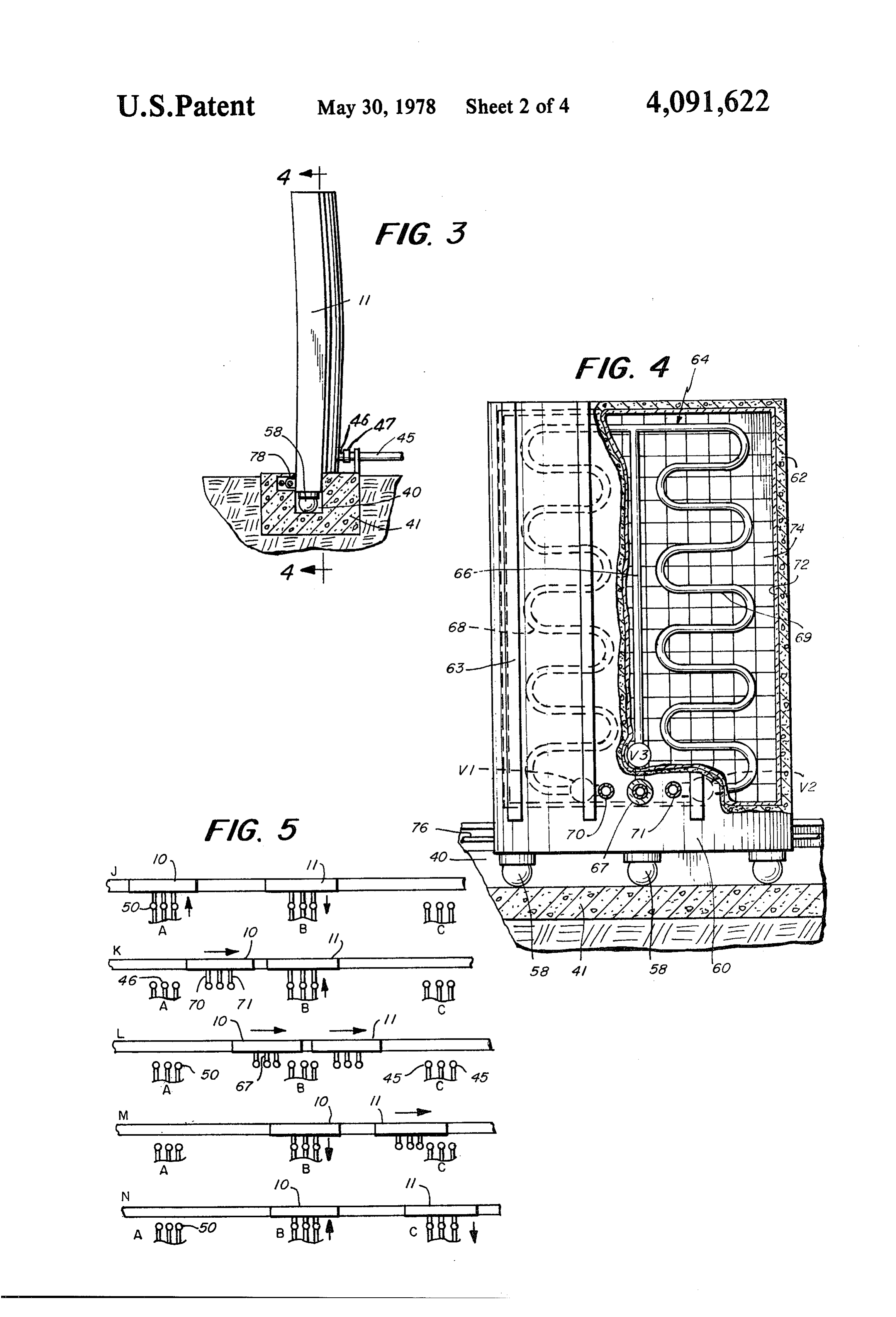
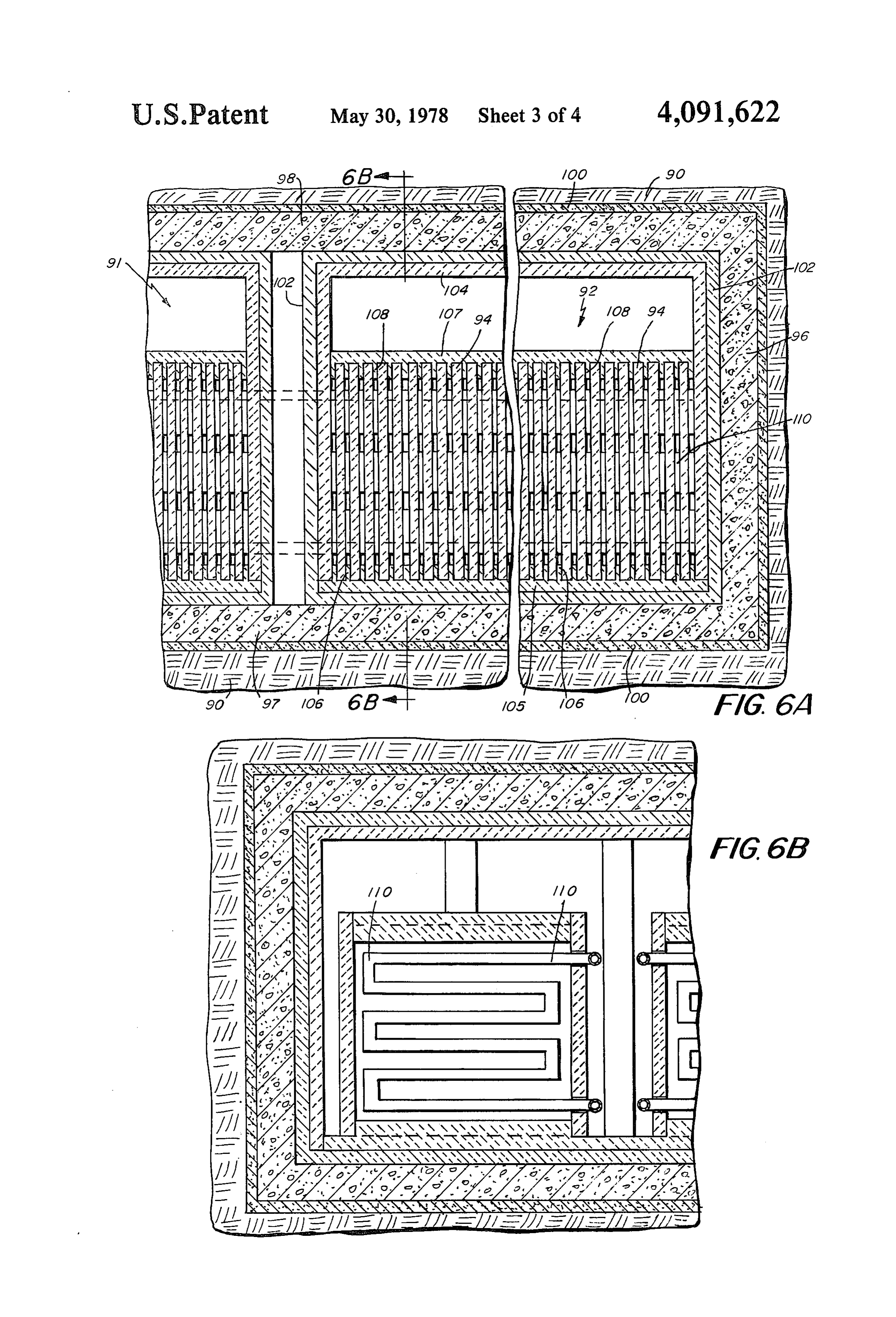
FIG. 2 is a schematic, plan view of a collector assem from radiation from sun 12 impinging on collector 10. bly according to the present invention and showing two The steam turbogenerators 20 are of conventional de sequentially operated collectors. sign and construction and receive overheated steam via FIG. 3 is a schematic, vertical, transverse sectional pipe 14. A boiler (not shown) is inserted between collec view of one of the collectors shown in FIG. 2 situated tor 10 and the turbogenerators 20 to insure a steady in a guide track. temperature of 600 F-700 F needed for an adequate FIG. 4 is a schematic, rear elevational view, partly functioning of the turbogenerators 20. cut away and in section with the section being taken FIG. 1B shows schematically a system which is sepa generally along the line 4-4 of FIG. 3. rate from that shown in FIG. 1A, and which is primar FIG. 5 is a schematic diagram showing a timing se 10 ily intended for use only in the nighttime. Thus, the quence which can be used to operate a system accord system shown in Fibure 1B comprises a collector 10A, ing to the present invention. a valve 18A, a pipe 14A, coupling members 22A, a pipe FIG. 6A is a fragmentary, vertical sectional view 16A and a pump 24A, all of which are identical to the taken through a heat storage unit according to the pres elements 10, 18, 14, 22, 16 and 24 as employed with the ent invention. 15 arrangement shown in FIG. 1A. This portion of the FIG. 6B is a fragmentary, sectional view taken gener system according to the invention also works in an ally along the line 6B-6B of FIG. 6A. identical manner to the arrangement previously de FIG. 7 is a schematic, front elevational view showing scribed with regard to FIG. 1A. The only exception is a motor drive arrangement suitable for propelling the that the overheated steam from pipe 14A is conveyed to collectors of the collector assembly according to the 20 a storage unit 26 constructed from a plurality of plates invention. formed from twice-baked clay. Reference to a specific FIG. 8 is a fragmentary, schematic, vertical trans embodiment of storage unit 26 will be made below in verse sectional view showing a further embodiment of a conjunction with FIGS. 6A and 6B.
collector according to the present invention. Storage unit 26 stores energy in the form of heat 25 during the period in the daytime when collector 10A is
DESCRIPTION OF THE PREFERRED receiving radiation from sun 12. The valves 28 are EMBODIMENTS closed during the heat absorption period. During the Referring now more particularly to the figures of the nighttime, however, these valves 28 are open and a drawings, the system of the present invention is prefera pump 30 is operated to force heated water or steam to bly provided in two sections, one for daytime use and 30 conventional steam turbo generators 32. The water the other for nighttime use. FIGS. 1A and 1B show, condensed in steam turbogenerators 32 and exhausted respectively, a day system and a night system, while therefrom is pumped by pump 30 back to the twice FIG. 1C shows an alternate arrangement to that shown baked clay storage unit 26 where it is reheated. This in FIG. 1B. Because the available solar energy can only pumping action continues and the overheated steam is be collected in the daytime, the night system must be 35 continuously provided to the steam turbo generators 32 provided with a storage unit for storing the energy during the entire period of this night usage. The electri needed to provide power during the nighttime. cal output thus generated is taken from the steam turbo FIG. 1A shows schematically a solar collector 10 generators 32 in a conventional manner and applied to positioned to receive rays from the sun 12. The specific an appropriate load (not shown). construction of collector 10 will be discussed in more 40 FIG. 1C is substantially identical to FIG. 1B, but detail hereinafter. Collector 10 can be constructed from with the exception that in FIG. 1C a boiler 34 of con a segment of a sphere, but preferably is a relatively flat ventional construction has been added to the assembly. element having a slight parabolic curvature. In addition, The boiler 34 is necessary in order to provide the steam collector 10 is preferably of relatively large size, and turbogenerators with an overheated steam of 600' can have dimensions of, for example, 30 meters by 45 45 F-700' F. This overheated steam is generated from the meters by 3 centimeters thick. suitable liquid 36 which is vaporized by the overheated Collector 10 includes a pipe arrangement partially steam in the pipe 35 to overheated steam 34, and is formed by an outlet pipe 14 and associated return pipe subsequently pumped by means of pipe 39 to the steam 16. A conventional valve 18 is disposed in pipe 14. Be turbogenerators 32. Pipe 39 has an asbestos cover in the cause collector 10 is movable, and the steam turbogen 50 manner of pipe 14A.
erators designated 20 are not movable, there must be Referring now more particularly to FIGS. 2 through provided a disconnect device 22. A disconnect device 4 of the drawings, a collector assembly according to the 22 is provided in each of the pipes 14 and 16. Actually, present invention will now be described. This assembly pipe 14 and pipe 16 each comprise separate pipe sec comprises a collector 10 and a collector 11, both of tions, with a pump 24 being located in one of the sec 55 which are disposed within a track 40. The assembly also tions of pipe 16. After the pipe arrangement of collector includes a plurality of stations A, B, C, D, E, F, and G, 10 has heated sufficiently, pump 24 is operated to force and steam turbogenerators 42. The track 40 extends in the steam thus generated by way of pipe 14 to the gener an arc and is arranged so as to be directed from east to ators 20. Valve 18 is open during this operation. After a west. The collectors 10, 11 would start in the early predetermined period of time, the steam is exhausted 60 morning in a westerly direction so that the rays from from collector 10, and pump 24 continues to pump cold sun 12, as shown by the direction arrows in FIG. 2, are water from turbogenerators 20 via pipe 16 to collector received from the east, and the collectors 10, 11 would 10. The collector 10 then moves toward a new station, progress along track 40 in a manner to be discussed as will be described below, and the water in the pipe hereinafter. In FIG. 2, collectors 10, 11 are shown in arrangement of collector 10 is heated during this move 65 their midday position with sun 12 directing its rays to ment. the collector 11. The embodiment shown in FIG. 2 is FIG. 1A shows the daytime system wherein turbo primarily for purposes of illustration. In an actual em generators 20 can produce an electrical output directly bodiment, there might be 200 stations that could be
Page 8
spaced even further apart than the spacing indicated in For controlling the pipe arrangement 64, there are FIG. 2. Each of the stations shown in FIG. 2 are sub provided valves V1,V2, and V3, which are respec stantially identical, and each includes a pump 44, input tively disposed in the bottom of pipes 68, 66 and 69. lines 45, and an output line 46 from the associated col These valves are basically in an open position when the lectors 10, 11. Each of the lines 45 and 46 has a conven collector 10, 11 is connected to a one of the stations A, tional disconnect device 47 to permit the collectors 10 B, and sequence, but are in a closed position when col and 11 to move along track 40 relative to lines 45 and lector 10, 11 is moving between the stations A, B, and 46. It will be appreciated that pump 44, lines 45 and 46, sequence. w and disconnect devices 47 are similar to pump 24, lines The collectors 10 and 11 have been mentioned as 14 and 16, and disconnect devices 22, as described 10 moving along the track 40. There is disclosed herein above. The collectors 10 and 11 are shown in a position two different techniques for moving the collectors 10, wherein the pipes comprising a part of the collectors 10 11. In FIGS. 3 and 4, there is shown a cable 76 which is and 11 are connected to stations C and D by means of connected to a tab 78 provided at the base of the associ the disconnect devices 47. The assembly shown in FIG. ated collector 10, 11. This cable 76 is either pulled so as 2 also includes a common input line 48 and a common 15 to move the associated collector 10, 11 in accordance return line 50. Steam from the collectors 10, 11 travels with a predetermined sequence to be described below, through line 50 to the steam turbo generators 42. or limit switches (not shown) can be provided arranged Cooled water is pumped by the pumps 44 in a selective in such a manner that the collector 10, 11 aligns itself manner via the line 48 to the connected collectors 10, properly with each of the stations A, B, and sequence, 11. Steam turbo generators 42 advantageously comprise 20 as indicated for collectors 10 and 11, and stations C and a conventional turbine 51, a condenser collector 52, and D, respectively, in FIG. 2.
a pipe 53 interconnecting turbine 51 and collector 52. FIG. 7 shows in a somewhat simplified form another After the steam has been used in turbine 51, the con arrangement for driving the collector 10, 11 in a selec densed liquid is collected by collector 52 and pump 44, tive manner. In FIG. 7, there is shown the collector 10, the latter of which is selectively operated for carrying 25 11 situated within the track 40. Adjacent to the track 40 the cooled liquid by means of pipe 48 back to the con there is provided a rack 80 which is engaged by a pinion nected collector 10 or 11. The sequence of operation of gear 82 driven by a conventional motor 83. Also associ the collector is controlled in a manner to be described ated with collector 10, 11 are suitable limit switches 84. below. Motor 83 is selectively operated to drive the gear 82, The collectors 10 and 11 are disposed extending into 30 which in turn engages the rack 80 and moves the entire the track 40. This track 40 is defined in a concrete slab collector 10, 11 along track 40. The limit switches 84 41 of sufficient size to support the weight of the collec are used to sense the position of the collector 10, 11 and tor 10, 11. More specifically, the collectors 10, 11 are stopthat same at the proper time by deenergizing motor 83 supported on roller bearings 58 which are suitably 35 so the collector 10, 11 is in the proper position to mounted on a base 60 of the associated collector 10, 11. connect with one of the stations A, B, and sequence. The base 60 of each collector 10, 11 is advantageously quence FIG. 5 of the drawings shows an example of a se formed of concrete, as is the outer shell 62 of the collec J, of operation for the collectors 10, 11. In position the collector tor 10, 11. There are also provided vertical concrete 44 is pumping cool 10 is coupled with station A and pump reinforcing ribs 63 for rigidifying the structure. The 40 same time, collectorliquid 11 has back into collector 10. At the just reached station B and is outer shell 62 of each of the collectors 10, 11 defines a delivering its steam under pressure chamber for containing a pipe arrangement 64 which quently to the turbo generators 42 to line 48 and subse
includes a vertical pipe 66 terminating in an output pipe In position K, collector 11 is still intercoupled at 67. Pipe arrangement 64 also includes a similar pair of station B, but the associated pump 44 is operating to meandering, or zig-zag, pipe sections 68 and 69 which 45 pump water into collector 11 has now expended all of respectively terminate in inlet pipes 70 and 71. The its steam. At the same time, collector 10 is moving away pipes 67, 70 and 71 all connect by means of disconnect from station. A towards station B. As collector 10 ap couplings 50 to the associated pipes of a respective one proaches of the stations A, B, and sequence, when the collector 11 disconnects from station Bin and station B, as indicated position L, collector starts to move 10, 11 is in the proper position in alignment with an 50 towards associated station, as seen in FIG. 2. The inside of the engaged at station B and is expelling its steam10into station C. In position M, collector is now the shell 62 is lined with an asbestos material 72, and the turbo generators 42. The collector 11 is still progressing like, for maintaining the heat collected by the collector toward station C. Finally, in position N, both of the 10, 11 within same. The surface collector 10, 11 facing collectors the sun 12 is defined by a plurality of glass squares 74 55 stations B 10 and 11 are interconnected, respectively, at and C.
which are darkened on their outer surface. Each of these squares may be, for example, 30 cm x 30 cm X 3 andAlthough not shown in FIG. 5, the valves V1,V2, V3 must also be operated in the proper fashion
There can be provided as many as, for example, 3,000 simultaneously
with the movements of collectors 10 and collector 10, 11 is at a respective one of the squares 74, or even more. Because the collector 10, 11 is stations A, B, and sequence, the valves V1,V2, and V3 moved so as to continuously focus with sun 12, the water or other liquid in the pipe arrangement 64 is can be opened, and when the collectors 10, 11 leave a station A, B, and sequence, the valves V1,V2, and V3 heated rather rapidly. The focusing of sun 12 is possible are then closed to permit steam to build up in the associ because of the distance of sun 12 from the solar collec ated pipe arrangement 64. This opening and closing can tor 10, 11. The absorption of heat is enhanced by mak be performed ing each square 74 with a black unpolished surface. The noid valves inina asuitable suitable manner as by the use of sole control system.
squares 74 may be held together with a special heat In addition, when the arrangement shown in FIG. 7 resistant cement known per se. for driving the collectors 10, 11 is employed, motor 83
Page 9
is operated in accordance with a specific timing se avilable, this stored energy is convected away from unit quence. This timing sequence may be established by 26 by means of the arrangement shown in FIGS. 1B and means of a conventional timer or controller which is not 1C, for example. During such energy conduction, the shown in the drawings, it being considered of conven valves 28 are then opened and the pump 30 is operated tional design. The controller functions to move the 5 to convey the heated liquid or vapor continuously to collectors in the manner discussed with reference to the turbo generators 32.
FIG. 5, whereby the motors 83 are operated in sequence In a large installation, it is contemplated that there and their operation may be interrupted upon arrival at a could be provided anywhere from 750 to 1,000 stacks of station A, B, and sequence, by means of the limit plates 94 such as stacks 91 and 92. It is also expected that switches 84. O the temperature will attain a value within unit 26 in the The heat storage unit 26 will now be described in range of 1,000 C to 1,200 C. The twice-baked clay conjunction with FIGS. 6A and 6B. This structure is used in unit 26 has, in addition to high heat storage preferably contained under ground, and is shown cov capability, the ability to withstand temperatures up to ered by earth 90. FIG. 6A shows two stacks 91 and 92 2,500' C for long periods of time.
each comprising a plurality of plates 94 formed from 15 It is important that the clay that is used in unit 26, twice burnt clay. While only two stacks 91 and 92 are which clay may be red clay or kaolin, be twice baked or illustrated, it is to be understood that a plurality of such fired, in order to improve the hardness and durability of stacks may be used, and can total ten or more such the clay, and render the plates 94 virtually maintenance stacks arranged in parallel to each other. free.
The stacks 91 and 92 are arranged in a concrete hous 20 Referring now to FIG. 8 of the drawings, there is ing including pillar 96. This pillar 96, together with a shown an arrangement of a collector 10, 11" which may concrete base 97 and a cover plate 98, are preferably be tilted slightly relative to its direction of movement constructed of a cementitious material, such as con along a track 40'. The latter is formed in a concrete crete, and the like. A layer 100 of asphalt or a similar platform 112, and receives a ball 114 in a race 116 in substance is provided over the concrete so as to be 25 cluding a troughed backing element 118 provided with between the concrete and the earth at the top and bot a graphite liner 120 and received in a concrete encase tom of the stacks and around the edges of the unit 26 as ment 122 provided in a recess 124 formed in the bottom well in order to hermetically seal the hole storage unit of track 40'. A cover 126 rides over the top portion of 26. the ball 114 and has connected thereto a T-bar 128 The inside of the concrete structure formed by pillar 30 received in a slotted track-portion formed on the lower 96, base 97, and plate 98 is lined first with an asbestos or face of a base 130 of the associated collector 10, 11'. By similar insulating material. A layer 104 formed from this arrangement, the collector 10, 11" can move along twice-baked clay is placed over layer 102, and on top of the longitudinal extent of track 40 by rotation ofball 114 layer 104 is positioned a plate 105 also formed from while the configuration of cover 126 permits the collec twice-baked clay and having spaced vertical flanges 106 35 tor 10, 11" to swing transversely about the longitudinal of the same material. There is a similar top plate 107 also extent of track 40 in order to permit adjustment of the having vertical flanges 108 constructed from twice angle of the collector 10, 11' relative to the sun. baked clay. The plates 94 are disposed intermediate the The collector 10, 11' is advantageously provided flanges 106 and 108 on the bottom and top plates 105 with a plurality of tubes 132, 132', and 132', each being and 107. The plates 94 can be about, for example, 175cm of a different length. Each of the support tubes 132, square and 4cm thick, and can be assembled in units of, 132, 132' includes a pair of sections 134, 134, 134" and for example, 100 plates 94 resting on plate 105. 136, 136 and 136' which telescopingly fit together. A The protrusions or flanges 106 and 108 serve as hold pin 138, or the like, can be provided for interlocking ers for the blocks or plates 94, and also add further to these two sections in predetermined positions. The back the volume of the twice-baked clay in which the heat 45 surface 140 of the collector 10", 11" has mounted thereon may be stored. a plurality of longitudinal brackets 142, 142, 142' to The blocks or plates 94 are separated by spaces which which the sections 134, 134, 134', respectively, can be are wide enough to allow uniform distribution of heat connected, while grooves 144 are provided in platform within the unit 26. In the embodiment shown in FIGS. 112 to receive balls 146 permitting the tubes 132 to 6A and 6B, a number of conductor pipes 110 are inter 50 move along tracks formed by grooves 144 which are leaved with the plates 94. In the preferred embodiment, substantially concentric with the track 40'. these conductor pipes 110 interconnect between the The tubes 132 may have suitable compression springs stacks 91 and 92, and the like, in order to provide a (not shown), and the like, disposed in the bottom por continuous flow through unit 26. These pipes 110 are tions of the sections 136, 136', 136' for biasing the col preferably constructed from twice-baked clay in order 55 lector 10, 11" toward the illustrated vertical position. to avoid a difference between the coefficient of expan Further, the longest tube 132 may be extended and sion of the pipes 110 and the plates 94 in view of the contracted as by a suitable motor (not shown) in con close proximity of the pipes 110 to the plates 94. The junction with a rack disposed along the outer extent of connecting pipes outside of unit 26 can be constructed the section 134. By this arrangement, if the total inclina of steel, and the like, preferably covered with a suitable 60 tion is to be 30, this motor drive may be driven slowly insulating material, such as asbestos. so that the collector 10, 11 inclines at a rate of approxi The space provided for the pipes 110, as defined by mately 5 per hour. At the middle of the day, the motor the flanges 106 and 108, may be about, for example, is driven in the opposite direction to then swing the 30cm. collector back to its vertical position. In operation, the unit 26 as set forth in FIGS. 6A and 65 Connected to the T-bar 128 is a lug 148 on which is 6B receives heat conveyed from the solar collectors 10, anchored a cable 150 for moving the collector 10, 11" 11 and stores such heat within the plates 94. During the along the race 116 of track 40'. To facilitate mainte nighttime, or other times when solar radiation is not nance of the ball 114 and race 116 arrangement of track
Page 10
40', a hatch 152 is advantageously provided in platform first rays of the sun with the sunrise on the following 112 so as to permit access to a suitable ladder 154 per morning as a function of its exact geographical latitude. mitting maintenance personnel (not shown) to enter It is to be understood that the three illustrated curved track 40. tubes as well as the ball 114 and associated cover 126, of Operation of the Collectors of Figures 2-4 and 8 a collector 10, 11" can be repeated along the longitudi nal length of the collector 10, 11' so that there may be,
The tracks 40, 40' are preferably arranged such that for example, a total of nine tubes and perhaps three such the collector 10, 11 or 10", 11 starts to move from west balls 114 in associated covers 126. to east at the precise instant that the first light rays of Summary the sun fall on the collector. The arch of the track 40, 10 40' will cause these rays to strike the collector perpen As can be readily understood from the above descrip dicularly to the arc of the collector from sunrise to tion and from the drawings, a combined day and night sunset because of the fact that the collector is always solar energy system according to the present invention directly opposite the sun. In this way, the collector does permits continuous power output with only the sun's not track the sun, but moves toward the sun on the sun's 15 input for energization. Because there are two collectors normal apparent trajectory toward the west. employed in this system, there preferably are two sepa With this, the best possible solution of the problem of rate motors for driving these collectors by either of the efficient heat absorption of solar energy is achieved in approaches diclosed herein: namely, using cables or that the sun and the collector move around a common using a rack and pinion motorized arrangement. The imaginary center and at the same distance from the 20 system may also be provided with a monitoring panel center. The sun's movement from east to west, as well for monitoring the activity of these motors as well as as the collector's movement from west to east, corre the different measurements of solar heat absorbed by spond to the earth's rotation around the sun. This also the glass plates, the temperature of the water and the makes possible a synchronized movement of both the steam in the pipe arrangements, the steam pressure and earth and the sun so as to keep the sun and the collector 25 flow at different points in the system, and the movement directly opposite one another, or at an angle of 180, as of the collectors. The display panels may be situated well as permitting the full solar sectional heat energy adjacent to the turbogenerators to allow a continuous radiation to fall on the entire area of the collector at an supervision of the entire system. This system is also angle of substantially 90' with respect to the collector, provided with suitable adjustment devices so that, for The sun does not move only in a horizontal orbit. 30 example, the tilting of the collectors can be made if so Soon after sunrise it starts to move above the horizontal desired.
line and reaches in this movement the highest point at The foregoing is considered as illustrative only of the approximately the noon hour. Then it declines back principles of the invention. Further, since numerous toward the horizontal line, crossing it again just before modifications and changes will readily occur to those sunset. The collector 10, 11" shown in FIG. 8 is in 35 skilled in the art, it is not desired to limit the invention tended to compensate for this vertical movement of the to the exact construction and operation shown and sun in its orbit relative to the horizon. described, and accordingly all suitable modifications The collector 10, 11’ performs the aforementioned and equivalents may be resorted to, falling within the compensation by tilting until approximately noon back scope of the invention.
wards from the full line position shown in FIG. 8 to the What is claimed as new is as follows: broken position therein, and in the afternoon back for 1. An energy conversion system, comprising, in com ward from the broken line position to the full line posi bination:
tion. Thus, the front surface of the collector always (a) first and second collector means for collecting remains directly opposed and perpendicular to the sun radiation from a source of radiation, each of the so as to receive the maximum incoming solar heat en 45 first and second collector means including a pipe ergy from sunrise to sunset. arrangement containing a fluid to be heated; The latter is achieved as follows: on the sun's double (b) support means for selectively moving the first and synchronical horizontal and vertical movements, the second collector means along a predetermined path sun's light rays come in contact with, for example, sele of movement;
nium cells (not shown) disposed in the crossing points of 50 (c) power generating means for converting into use a, for example, reinforced concrete lattice supporting ful energy the thermal power collected by the first the glass squares 74. This contact establishes current in and second collector means; and the selenium cells. This current is transferred to a con (d) station means disposed along the predetermined trol panel (not shown) advantageously situated near the path of movement for selectively coupling the pipe central panel of the associated collector 10, 11'. On this 55 arrangement of each of the first and second collec control panel, there are situated points correcponding tor means to the power generating means. exactly to the position of the selenium cells on the col 2. A structure as defined in claim 1, further including lector. The current received at the points causes, in a heat storage means comprising a plurality of heat absor known manner, swinging movement of the collector bent plates formed from twice-baked clay, and coupling about a horizontal axis as a function of the received means connected to the heat storage means and the first impulses, and if a motor drive, as shown in FIG. 7, is and second collector means for carrying heat to the employed, can also cause movement of the collector storage means during periods when radiation from the along its track 40, 40'. In this manner, it is the sun itself source of radiation is impinging on the first and second which primarily initiates and proceeds to direct the collector means.
movement of the collector 10, 11' when equipped with 65 3. A structure as defined in claim 2, wherein the heat a motor drive, as shown in FIG. 7. storage means includes control means for preventing After sunset, the collector is returned to its starting conveyance of heat from the heat storage means to the point on track 40, 40' and is adjusted so as to meet the power generating means during periods when radiation
Page 11
is impinging on the first and second collector means, 6. A structure as defined in claim 5, wherein the heat and permitting conveyance of heat from the heat stor storage means further includes a top plate and a bottom age means to the power generating means at other plate both formed from twice-baked clay and each hav times. ing a plurality of spaced flanges extending perpendicu larly therefrom, the plates being spaced beneath and 4. A structure as defined in claim 3, wherein the 5 above power generating means includes first and second gen extending the plurality of stacked plates, with the flanges between adjacent ones of the stacked plates in erating assemblies, the first of these generating assem order to space blies being connected directly to the first and second the stacked plates from one another. 7. A structure as defined in claim 6, further including collector means, and the second of these generator as O a concrete housing for containing the plates, the hous semblies being connected directly to the heat storage ing being covered by a layer of asphalt and by earth 2S, such that the heat storage means is contained totally 5. A structure as defined in claim 2, wherein the heat underground.
storage means includes a plurality of pipe sections dis 8. A structure as set forth in claim 1, wherein the posed between the twice-baked clay plates for transfer 15 support means includes drive means for independently ring heat between a fluid contained in the pipe sections moving the first and second collector means. and the plates.
Provenance
- Collection
- Cited prior art
- Original PDF
- patentimages.storage.googleapis.com →
- Filed
- 1976-11-29
- Pages
- 11
- Method
- pdftotext (the PDF's own text layer) + pdftoppm 300dpi page scans
- Source
- Google Patents bibliographic record
- Granted
- 1978-05-30
- Inventors
- Carlo M. Marchesi
- Transcribed from
- patentimages.storage.googleapis.com →