patent · US2396338
Radiation heating and cooling system
12 March 1946
Page 1
Drawing sheet — no readable text.
Page 2
Drawing sheet — no readable text.
Page 3
Patented Mar. 12, 1946 2,396,338
UNITED STATES PATENT OFFICE
RADATION HEATNG AND COOLNG
SYSTEM
Alwin B. Newton, Minneapolis, Minn, assignor to -Minneapolis-Honeywell Regulator Company,
Minneapolis, Minn., a corporation of Delaware
Application February 24, 1943, Serial No. 476,891
The present invention relates to heating and means for heating and cooling Such storing Cooling by the transfer of heat from and to the means.
universe by means of a radiation unit and con Another object of the present invention is to stitutes an improvement upon my co-pending ap control such additional heating and cooling plication Serial No. 415,433, filed October 17, 1941, means by the temperatures of the heat and Cold now Patent No. 2,342,211, issued February 22, 1944, storing means. Preferably, such additional heat and entitled "Utilization of natural heating and ing and cooling means are placed in operation cooling effects.' upon a further fall or rise in space temperature, It is an object of my present invention to heat as the Case maybe.
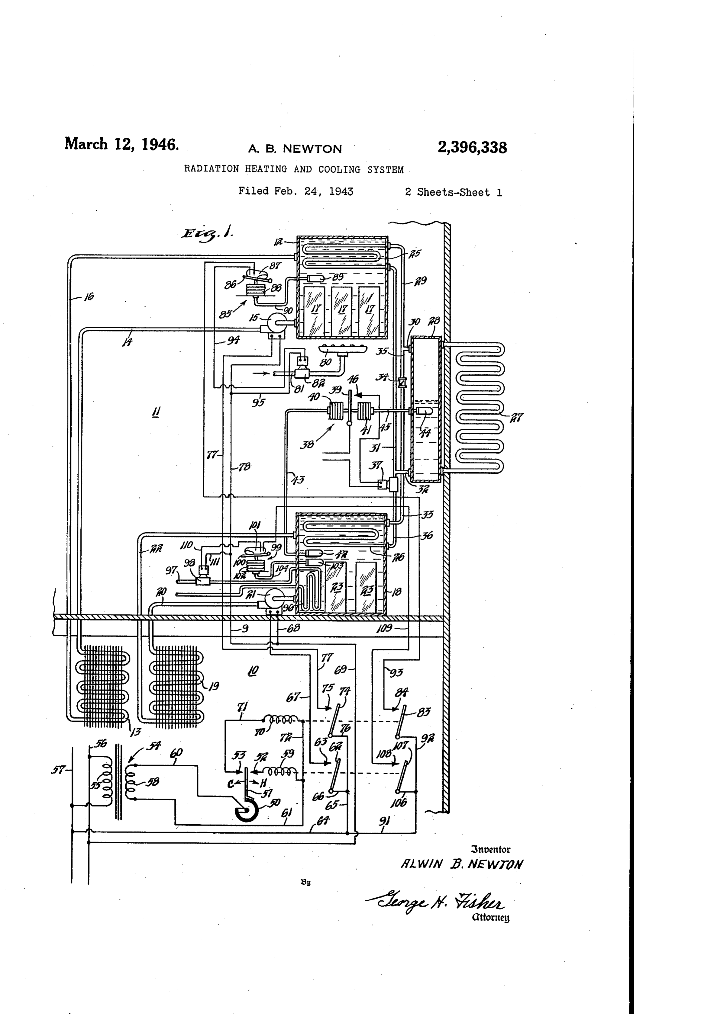
and cool a space, according to the requirements 10 It is another object of my invention to place of Such Space, by providing independent heat and the additional cooling means into operation be cold storing means which are respectively heated fore the Space temperature, rises to a high value and COOled by a single radiation device so ar if the humidity is high when an intermediate ranged as to permit the transfer of heat between rise in space temperature occurs. such device and the universe by radiation so that 15 Another object of the present invention is to the device is heated by radiation from the sun provide a closed fluid system having a first heat during the daytime and is cooled by radiation exchange portion for heating a heat storing from the device to the universe at night. means and a second heat exchange portion for It is a further object of my invention to pro cooling a cold storage means together with a vide means, preferably in the nature of auto 20 radiation portion exposed to the universe, the natic means, for selectively permitting the radia fluid System being charged with a volatile fluid, tion device to heat the heat storing or cool the as distinguished from being completely filled with Cold storing means, depending upon the relative a heat transfer liquid. - temperatures of Some or all of the heat and cold Other objects of the invention will become ap storing means and the radiation device. 25 parent from the following detailed description In one form of my invention, the heating or and the accompanying drawings, in which: Cooling of the heating and cold storing means is Figure i discloses one type of system con controlled by the temperature differential between structed in accordance with my present invention the radiation device, or the fluid therein, and Wherein the closed fluid system is charged with a the temperature of one of the storing means. It 30 volatile fluid, is therefore a further object of my invention to Figure 2 is a modification of the system of Fig control the effect of the radiation device in respect lure I employing a two-stage type space thermo to the heat and cold storing means in accordanc stat, and
With such differential temperature. Figure 3 is a modified system in which the ra In another form of my invention, the effect of 35 diation device and associated heat transfer the radiating means or device upon the heat and means are completely filled with a liquid. cold storing means is controlled by the tempera Referring to Figure 1, a portion of a building ture of the fluid flowing through the radiation is shown therein which includes a space O to device. It is therefore a further object of the be heated and cooled and a further space it present invention to permit heating of the heat 40 which may, for example, be the attic or top floor storing means by the radiation device when the of the building. Located in the attic f f is a heat temperature of the fluid flowing through such storing means shown in the form of a tank 2 device is at or above a predetermined temperature, filled with a suitable heat transfer medium, pref and to permit Cooling of the cold storing means 45 The erably one having a relatively low freezing point. by the radiation device when the temperature of lower portion of the heat storing means 2 the fluid flowing therethrough is at or below is connected to a heating coil 3 located in the predetermined temperature. Space 0 by a pipe 4. The pipe 4 may contain A further object of the present invention is to any desired type of flow controlling means and such a means is herein shown as an electrically control the effect of the heat, and cold storing 50 operated pump 5. The other end of the heating means upon the space in accordance with fluctua coil 3 is connected to the top of the heat storing tion in the space temperature. means 2 by a pipe f6. In order to increase the Additionally, it is an object of my invention to heat storing capacity of the heat storing means Supplement the action of the heat and cold stor 2, it may be provided with containers f which ing means by additional heating and cooling 55 contain a substance, such as Wood's metal, as
Page 4
mentioned in the aforesaid patent, that Solidifies methylchloride or any of the various Freons. at or about the temperature which it is desired The system is not completely filled with the fluid to maintain in the heat storing means 2 in order so that there is always a certain amount of that a larger amount of heat may be stored liquid as well as a certain amount of gas or vapor, therein for a given capacity of the tank forming the liquid level being shown in the header 28 the heat storing means. which is in cross-section.
Also located in the attic f is a cold storing The electrical valve 37 is herein shown con means 8 in the form of a tank which is like trolled by a differential temperature responsive wise filled with a liquid. The bottom of the O device 38 which responds to the difference in cold storing means 8 is connected to a cool temperature between the liquid in the header ing coil 9 by a pipe 20. The pipe 20 may be 28 and the heat exchange fluid in the tank or provided with any suitable flow controlling means cold storing means 8. This differential tem herein shown as an electrically operated pump 2. perature responsive device 38 includes a piv The other end of the cooling coil 9 is connected oted arm 39 actuated by a pair of bellows 40 near the top of the cold storing means 8 by a and 4. The bellows 40 bears on the left-hand pipe 22. The cold storing means 8 may like side of the arm 39 and is connected, by means wise be provided with containers 23 having suit of the usual tubing 43, to a temperature con able substances therein, such as listed in my trolling bulb 42 located in the tank 8. The aforesaid patent and including acetaldehyde, so bellows 4 bears on the right-hand side of arm as to increase the storage capacity of the cold 20 39 and is connected to a temperature responsive storing means 8. bulb 44, located in the header 28, by a tube 45. The heat storing means 2 and cold stor When the temperature of the fluid in the header ing means 8 are arranged to be heated and 28 is substantially equal to the temperature of cooled respectively by means of a closed fluid the liquid in the cold storing means, the arm system that includes a first heat exchange por 25 39 is substantially vertical, as shown, wherein tion 25, a second heat exchange portion 26, and it is disengaged from a contact 46. On the other a radiation portion 27. The heat exchange por hand, when the temperature is less in the header tion 25 takes the form of a coil located within 28 than in the tank 8, the arm 39 Swings to the heat storing means or tank 2. Similarly, the right and engages contact 46 so as to ener the heat exchange portion 26 comprises a pipe 30 gize and open the electrical valve 37 by a circuit coil located within the cold storing means or which is obvious upon an inspection of the draw tank 8. The radiation portion 27 also takes lingS.
the form of a pipe coil but such radiation por With the parts in the position shown and as tion 27 is so located as to permit the radiation suming that it is in the daytime and the Sun is of heat to it from the sun as well as to permit 35 shining, then the temperature of the radiation the radiation of heat from the radiation por portion 27 will be relatively high due to the radia tion 27 to the universe at night when the Sun tion of heat thereto from the Sun. The volatile is not shining. To this end, the radiation por liquid contained in the radiation portion 27 will tion 27 has been shown as located outside of therefore be vaporized and this vapor will pass the building. Although the radiation portion 27 40 into the upper end of header 28 and then, by way in this diagrammatic showing is entirely ex of pipes 30 and 29, will pass to the head exchange posed, it should be understood that it could be portion 25. Since the temperature of the liquid enclosed by some suitable means, such as one in the tank 2 will not be as high as the tempera of the forms of Lucite, which permits the radia ture of the volatile fluid in header 28 under the tion both of high and relatively low temperatures action of the Sun, the vapor Orgas passing to the so that the heat from the Sun can be radiated heat exchange portion 25 Will be condensed there to the radiation portion 27 during the daytime in until such time as the vapor pressure is com and at night the relatively higher heat of the mensurate with the temperature of the liquid in radiation portion 27 may be radiated to the uni the tank 2. This condensed liquid will flow back WeSe. 50 to the header 28 by Way of pipes 3 and 32. In addition, this closed fluid system includes a So long as the temperature of the radiation por header 28, to the top of which the upper end tion 27 is higher than the temperature of the of the radiation portion 27 is connected. Also, liquid in the tank 2, this action will continue the lower end of the radiation portion 27 is con even though these temperatures vary. This is nected to the lower portion of the header 28. 55 true since the vapor or gas will only be condensed The heat storing means 2 is located above the by the heat exchanger 25 to an extent depending header 28 and the heat exchange portion 25 upon the temperature of the liquid in the tank located therein has its upper end connected to 2. However, so long as the temperature of the the upper end of the header 28 by means of pipes radiation portion 27 is higher than the tempera 29 and 30. The lower end of heat exchange 60 ture of the liquid in the tank 2, further evapo portion 25 is connected to the lower end of head ration will take place in the radiator portion 27. er 28 by pipes 3 and 32. The cold storing means On the other hand, if the Sun should be so ob f8 is located below the header 28 and the upper Scured as to reduce the temperature of the radia end of the heat exchange portion 26 is connected tion portion 27 or if the temperature thereof be to the upper end of header 28 by means of a 65 comes reduced by reason of night falling, than pipe 33, a check valve 34, a pipe 35, and pipe the radiation portion 27 Will become the con 30. The check valve 34, as indicated, permits denser. AS Soon as all the liquid within the heat the flow of fluid upwardly through the pipes exchanger 25 has been evaporated due to the 33 and 35 but prevents downward flow there higher temperature therein, and flows down to through. The lower end of heat exchange por O the header 28, there no longer will be vapor or tion 26 is connected to the lower end of header gas present and, since the liquid cannot flow up 28 by a pipe 36, electrically operated valve 37, to the heat exchanger 25, no further exchange of and the pipe 32. This complete fluid system, heat from the liquid in the tank 2 to the radia which is entirely closed, is charged with a vola tion portion 27 will take place. In this manner, tile fluid. This fluid may, for example, be 75 heat exchange can take place in only one direc
Page 5
tion between the radiation portion 27 and the may be impossible to store sufficient cooling capac liquid in the tank 2 and this is in a direction to ity to adequately cool the space . The present 'heat the liquid in the tank 2 when the radiation invention therefore contemplates providing an portion 2 is at a higher temperature than Said additional Source of heat for the heat storing liquid. means 2 and an additional source of cooling for Let us now assume that the night is very clear the cold storage means 8. To this end, a heating and conditions are such that the liquid in the means in the form of a burner 80 is shown located header 28 becomes cooler than the liquid in the under the heat storing means f2. This burner is tank 8. Under such conditions, the arm 39 will Supplied with fuel by a fuel supply pipe 8 in engage contact 46 and valve 37 will be energized. O which is located an electrically operated valve There is now free communication between the 82. This valve is controlled in part by a switch botton of header 28 and the heat exchanger 26. arm. 83 and associated contact 84 operated by the Liquid will therefore flow through pipes 32 and relay coil to and also in part by a thernostat 85 36 to the heat exchanger 26. Since the heat ex Which responds to the temperature of the liquid in changer 26 is at a higher temperature than the 5 the heat storing tank 2. The thermostat 85 in liquid in the header 28, such liquid will be evapo cludes a pivoted arm 86 which supports a mercury rated and Will flow to the top of the header 28 by Switch 87 and is positioned by a belows 88 that way of pipe 33, check valve 34 and pipe 35. Such is in turn connected to a temperature responsive evaporation of the volatile fluid removes heat bulb 89 by a tube SC. The temperature responsive from the liquid in the tank 8 so as to cool such 20 bulb 89 is located within the tank 2 so as to re liquid. In this manner, the cold storing means is Spond to the temperature of the liquid therein. cooled, When the temperature of this liquid is too low, Thus, by the use of a volatile fluid and a single the bellows 88 contracts permitting counter electrical valve together with a check valve, the clockwise movement of switch supporting arm 86 radiation portion 2 is utilized to selectively cool about its pivot, whereupon mercury switch. 8 the cold storing means and to heat the heat stor moves to its closed circuit position. Whenever ing means. These stored heating and cooling the mercury Switch 87 moves to its closed circuit capacities are then utilized to heat and cool the position, and provided relay coil 0 is energized as Space 6 in accordance with demands in the foll a result of a demand for heat by the room ther lowing manner. The space O is provided with a 30 mostat, a circuit for the fuel Valve 82 is estab room thermostat comprising a coiled bimetal ele lished as follows: line wire 57, wire 64, wire 9, ment 50 having one end relatively fixed and sup wire 92, switch arm 83, contact 84, wire 93, mer porting a contact arm 5 at its other end. The cury SWitch 8, wire 94, fuel valve 82, wire 95, wire contact arm 5 is adapted to selectively engage hot 8, wire 9, and wire 69 to the other line wire 56. and cold contacts 52 and 53. Power is supplied Therefore, whenever the room thermostat de to the room thermostat by a transformer 54 of mands heat, if the liquid in the tank 2 is not the step-down type having a high voltage pri Sufficiently hot as determined by the thermostat mary 55, connected to suitable line wires 56 and 85, then auxiliary heat is furnished to the heat 5, and the usual low voltage secondary 58. Upon storing means 2 by the burner 80. - a demand for cooling by the room thermostat so 4) In a similar manner, the cooling tank 8 is that the contact arm 5 engages the hot contact provided with a cooling coil 96 that is supplied 52, a relay coil 59 is energized as follows: from the with any suitable type of cooling means by a pipe upper end of Secondary 58, wire 60, room thermo 97. The flow through pipe 97 is controlled by an electrically operated valve 98, which is controlled stat 50, contact arm 5, hot contact 52, relay coil 45 in 59, and wire 6A back to the lower side of secondary part by the relay coil 59 and in part by a ther 58. Relay coil 59, when energized, moves a switch mostat 99. The thermostat 99 includes a switch arm 62 into engagement with a contact 63. This arm 00 that carries a mercury switch O in energizes the electrical pump 2 by a circuit as turn positioned by a bellows 02 that is connected follows: line wire 57, wire 64, wire 65, wire 66, 50 to03aiscontrolling bulb 03 by a tube O4. The bulb Switch arm 62, contact 63, wire 67, pump 2, wire ment located within the tank 8 and the arrange is such that when the temperature of the 68, and wire 69 to line wire 56. The pump 2 liquid in the tank 8 is too high, bellows f O2 ex thereupon forces the cold liquid in the tank 8 to the cooling coil 9 so as to reduce the temperature pands thereby tilting switch arm OO so as to of the space 0. move mercury Switch of to closed circuit posi 55 tion. When this occurs, the cooling valve 98 is
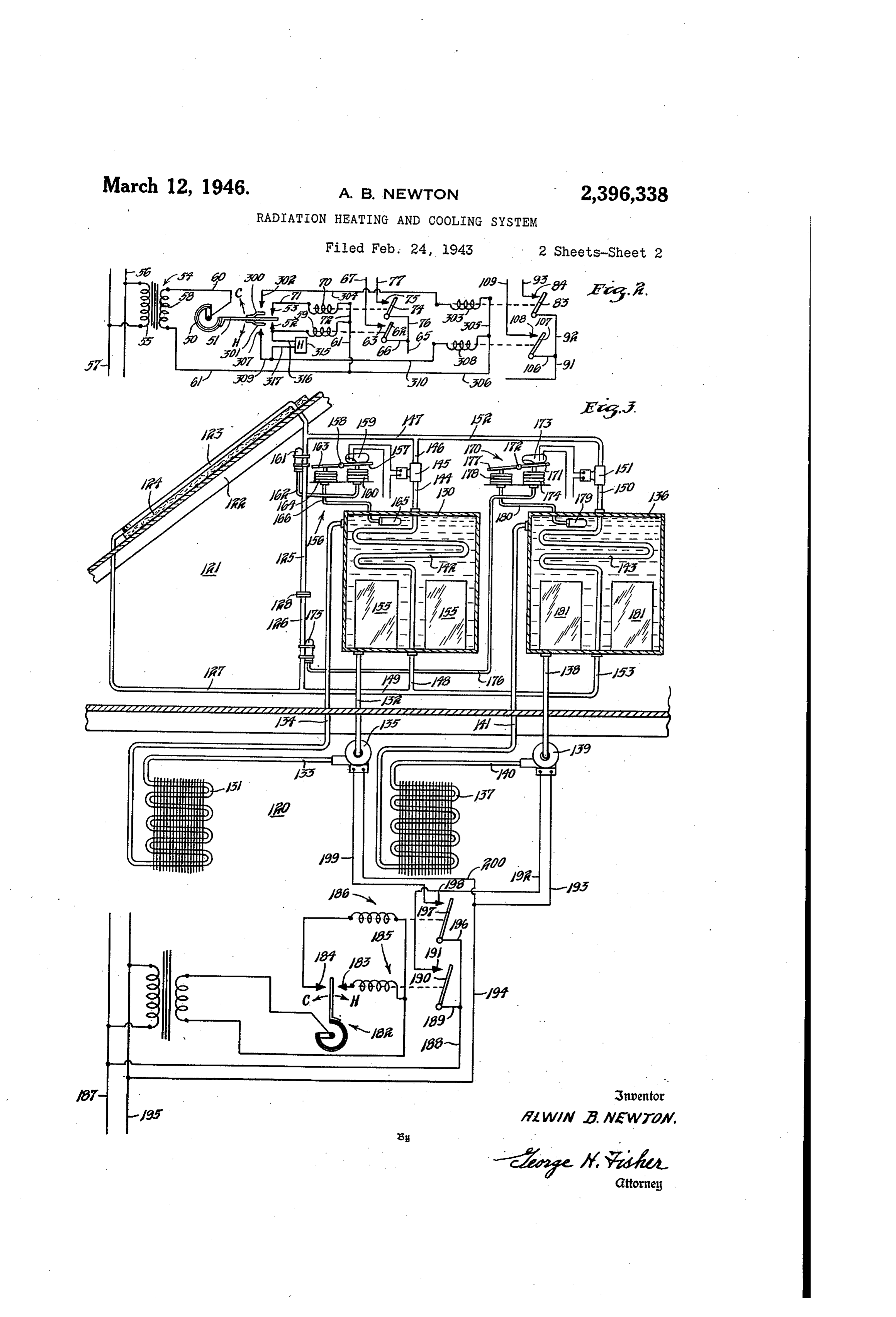
If, on the other hand, the temperature of the opened provided the room thermostat is demand Space to becomes too cool, the arm 5 of the ther ing cooling at such time. This circuit is as foll mostat engages the cold contact 53. This en ergizes a relay coil 70 as follows: from the upper lows: line wire 57, wire 64, wire 9, wire 06, a end of secondary 58, wire 60, room thermostat switch arm 07 operated by relay coil 59, a co coil 50, contact arm 5, cold contact 53, wire 7, 60 operating contact 08, wire O9, mercury switch relay coil 0, wire 72, and wire 6 to the lower 0 , wire to, cooling valve 98, wire f , wire 9, end of Secondary 58. Energization of relay coil and Wire 69 to the other line Wire 56. In this moves a Switch arm 74 into engagement with manner, whenever there is a demand for cooling, a contact 5 to thereby energize the electrically 65 and if the liquid in the cold storing means 8 is Operated pump 5 by a circuit as follows: line wire not sufficiently cold as determined by the thermo 57, wire 64, wire 65, wire 76, switch arm 4, con stat 99, the cooling valve 98 is opened so as to tact 5, wire 77, pump 5, wire 78, wire 9, and wire further reduce the temperature of such liquid. 69 to the other line wire 56. In this manner, when Figure 2 shows a modification of the control the room 0 is too cold, the pump 5 forces the O System of Figure 1 wherein the auxiliary heating heated water in the tank f2 to the heating coil 3 and cooling means are normally brought into op SO as to raise the space temperature. eration only upon a further fall or rise in the Under certain conditions, it may be impossible Space temperature, as the case may be. Since to store Sufficient heat in the heat storage means many of the circuits are the same as those pre f2 to adequately heat the space O and likewise it 5 viously described in Figure 1, similar reference
Page 6
characters have been used on such circuits in wire 6 to the lower end of secondary 58. In Figure 2. this manner, upon an intermediate rise in room. This action is accomplished by placing the con temperature and if the humidity is excessive, then trol of switch arms 83 and 107 under additional the auxiliary cooling means is brought into op relays operated by additional contacts on the eration so as to lower the temperature of the space thermostatinstead of operating such Switch stored cooling fluid, under the control of thermo arms by the relay coils 70 and 59. To this end, stat 99, to reduce the temperature of the cooled the contact arm 5 of the room thermostat 50 is fluid sufficiently to bring about a dehumidifying made relatively flexible. On one side of the con action.
tact arm 5 and at an intermediate point, a fur 10 Turning now to Figure 3, a further form of ap ther contact arm 300 is attached. A similar con paratus is disclosed which uses a closed liquid tact arm 30 is attached to the other side of the system. A room or space 20 to be heated and contact arm 5 and at an intermediate point cooled comprises a portion of a house having an thereon. When the room temperature becomes attic 2 and a roof 22. "Located on the roof 22 somewhat lower than that value at which contact 5 is the radiation portion 23 of the closed liquid arm 5 engages contact 53, then the contact arm system. This radiation portion 23 is shown as 300 engages a contact 302 and thus energizes a being suitably insulated from the roof by insulat relay coil 303 by a circuit as follows: upper end of ing material 24. The liquid circuit through the secondary 58, wire 60, element 50, contact arm 5, radiation portion 23 is closed so as to form a contact arm 300, contact 302, wire 304, relay coil 20 complete or closed loop by means of pipes 25, 303, wire 305, wire 306, and wire 6 to the lower 26 and 2. An orifice if 28 is located between end of secondary 58. Energization of relay coil the pipes 25 and 26. So as to restrict the flow 303 moves switch arm 83 into engagement with through this closed loop. In order to provide contact 84 to establish the previously traced cir for expansion and contraction of the liquid in cuit for the valve 82 of the auxiliary heating 25 the closed liquid System, it may be provided with means, provided the thermostat 85 which re an expansion tank, if desired, as is usual practice sponds to the temperature of the stored heating in the heating art.
fluid is closed. located in the attic 2 is a heat storage means When the temperature rises sufficiently above 30 in the form of a tank filled with liquid. This that value at which contact arm 5 engages con 30 tank is connected to a heating coil 3 located in tact 52, then contact arm 30 to engages a contact the room 20 by means of pipes. 32, 33 and 34, 307 to energize a relay coil 308 as follows: upper there being an electrically operated pump 35 end of secondary 58, wire 60, element 50, contact connected between pipes, 32 and 33. Similarly, arm 5, contact arm 30, contact 30, wire 309, a cold storing means in the form of a tank 36 wire 30, relay coil 308, wire 306, and wire 6 to is likewise located in attic f2. This tank is filled the lower end of secondary 58. Energization of With liquid and is connected to a cooling coil 3 relay coil 308 moves switch arm 0 into engage located in the room 20 by a pipe 38, a pump 39, ment with contact 08 to thereby energize the a pipe 40, and a pipe f4. The tanks 30 and valve 98 of the auxiliary cooling means provided 36 may also be provided with the usual expan the temperature of the stored cooling fluid is suff Sion tanks if desired.
ciently high that mercury Switch 00 of the stored The closed fluid system, in addition to the cooling fluid responsive thermostat 99 is closed.
Thus, with the arrangement of Figure 2, upon change loop, closed further includes a first heat ex portion 42 located in the heat storage a first temperature fall the space will be heated by the stored heating fluid if such fluid is suff 45 tank located 30 and a second heat exchange portion 33 in the cold storing tank 36. The upper ciently high in temperature. However if this end of heat exchange portion 42 is connected to heating fluid is not at a high enough temperature the upper end of pipe 25 by pipe 44, an elec so that the room temperature falls further, then trical valve 45, a pipe 46, and pipe 47. The the auxiliary heating means is brought into op lower end of the heat exchange portion 42 is eration. This conserves upon the auxiliary heat 50 connected to the junction of pipes 26 and 2. ing means since it is obvious that it will not al by pipes f48 and 49. Likewise, the upper end of ways be necessary to utilize auxiliary heat in heat exchange portion 43 is connected to the up order to maintain desired room temperatures. per end of pipe 25 by a pipe f 50, an electrical Similarly, during warm weather, upon rise in Valve fS, a pipe 52, and pipe 47. The lower room temperature it is first attempted to reduce 55 end thereof is connected to the junction of pipes the room temperature by the Stored cooling fluid f26 and 27 by a pipe 53 and pipe 49. without the use of any auxiliary cooling. How ASSuming that the valve f45 is open and the ever, if the stored cooling fluid is too high in tem valve 5 is closed and that it is daytime and the perature and the room temperature rises further, Sun is shining, the radiation portion 23 will he then and only then is the auxiliary cooling means 60 at a relatively high temperature due to radiation brought into operation.
It is conceivable that the temperature of the from the Sun. As mentioned above, this system stored cooling fluid may be sufficiently low to is a liquid System which is completely filled with prevent excessive rise in room temperature and liquid as distinguished from a volatile fluid sys engagement of contact arm 30 with contact 307 65 tem. The liquid in the radiation portion 23 upon being heated will flow upwardly and part but still not be low enough to cause any apprecia of it will flow continuously through the pipe 25, ble dehumidification. A Space humidity con the restricting orifice 28, the pipe 26 and the troller 3 5 is therefore arranged in Figure 2 in pipe 27 to the lower end of the radiation por such manner as to energize relay coil 308 and tion bring on the auxiliary cooling means upon high 70 portion23.of Also, this since valve 45 is open, the major hot liquid will flow from the upper humidity even though the room temperature is end of radiation portion 23 by way of pipe 47, not excessive. This circuit is as follows: upper end of Secondary 58, wire 60, element 50, contact pipe f46, valve 45, and pipe f44 to the heat ex arm 5, contact 52, wire 3 f6, humidity control changer 42. It will flow from the heat ex 35, wire 3 7, wire 30, relay coil 308, wire 306, and changer by way of pipes f48, 49 and 27 back 5 to the lower end of the radiation portion 23. In
Page 7
this manner, the liquid in the tank 30 will be through the radiating portion 2S, where it will heated. In order to increase the heat storage lose heat to the universe. It will then foW from capacity of the tank 30, containers 55 may be the lower portion of radiating portion 23 to the provided therein filled with a suitable Substance lower end of pipe 26 by way of pipe 2. Let us as explained in connection with the containers 5 now assume that the temperature of the water A of Figure 1. fiowing through the closed loop is thus reduced The valve 85 may be controlled in any de to 60 degrees. At this time, let us assume that sired manner. I prefer to control it by tempera valve 5 is open. The flow of Water through ture and for this purpose provide a temperature the closed loop of course is restricted by the responsive means 56. This temperature respon 0 orifice 28 and, with valve 5 open, the major sive means may take the form of a straight tem portion of such cold water will flow from the perature thermostat but preferably takes the lower end of radiation portion 23 through pipe form of a differential temperature thermostat. 27, pipe 49, and pipe 53 to the lower end of It includes a switch operating arm 5 pivoted heat exchanger 43 located in the cold storing at 58 which carries a mercury switch 59. The means or tank (36. This flow of liquid will re arm 5 is operated by a bellows 60 connected suit in the lowering of the temperature in the to a temperature controlling bulb 6 by a tube tank 36. At the same time, such liquid flowing 62. The bulb 6 is secured in any usual man through the heat exchanger 63 will pick up heat ner to the pipe 25 so that it responds to the and rise in temperature. This will help the temperature of the liquid flowing therethrough. liquid to continue its flow back to the upper With as much of the apparatus 56 as thus far end of the radiating portion 23 by way of pipe described, the mercury switch 59 will be op i50, valve 5, and pipe 52. erated entirely by the temperature of the fluid The valve 5 is automatically controlled by a or liquid flowing through the pipe 25. When temperature responsive mechanism if 0. Here the temperature of this liquid is high enough, 2 s again, this temperature responsive mechanism say 90 degrees, the mercury switch 59 will be could comprise a simple thermostat. This moved to the closed circuit position in which it mechanism includes an arm , pivoted at 2, is shown so as to open the valve 5, whereupon which supports a mercury switch 3. The arm heating of the liquid in the tank 30 will take is operated by a bellows 4 connected to a ten place. I prefer however to operate mercury 30 perature bulb ft 5 by a tube 76. The bulb 75 switch 59 in accordance with the temperature responds to the temperature of the liquid flow differential between the liquid in tank 30 and ing through the pipe 26. If only a simple ther the temperature of the fluid flowing through mostat as thus far described is used, it could be pipe (25. To this end, the arm 57 is provided set for example at 60 degrees So that mercury switch 3 would close whenever the tempera with an extension a 63 which extends to the left 35 ture of pivot 58. A bellows f4 operates upon the of the liquid flowing through pipe 26 fell extension 63 in opposition to the bellows 60. to 60 degrees or lower. Under Such conditions The bellows 64 is connected to a temperature then, the valve f S would be opened and the controlling bulb 65 by a tube 66. The tem operation by which the liquid in tank 36 is perature differential instrument is set so that 40 lowered in temperature would take place as out mercury Switch 59 is only closed when the tem lined above. Here again, however, I prefer that perature of the liquid flowing through the pipe the temperature responsive mechanism. To be a 25 is a predetermined amount higher than the differential temperature type of apparatus so temperature of the liquid in the tank 30. In that cooling of the iquid in the tank 36 may this manner, whenever the temperature of the take place even at temperatures of 75 or 70 de fluid is sufficiently high to raise the temperature grees where no cooling action has been available of the liquid in tank f30, it is used for this pur for a substantial period, as for example due to pose. This is better than having the plain ther the sky being cloudy for one or more nights. nostat since, under conditions where there has Arm T is therefore provided with an extension been no appreciable heating of the radiating por f77 against which a bellows 78 bears. The tion 23 for a considerable length of time, the bellows 78 is connected to a temperature bulb fluid in tank 30 might be cold enough that there 79 by a tube 80. The bulb 9 is located in the would be no utility in waiting until the tem tank f36. This differential temperature respon perature of the liquid passing through pipe 25 sive mechanism is set So that mercury Switch has been raised to 90 degrees. Under such con 5 s 73 is closed whenever the temperature of the .ditions, the liquid, in tank 30 might well be liquid flowing through pipe 26 is below that of heated even though the temperature of the liquid the liquid in the tank 36 by a predetermined passing through pipe 25 were only 75 or 80 de amount. In order to increase the storage greeS. capacity of the cold storing means 36, contain Assume now that it becomes night and it is a 6) ers 8 may be placed therein filled with a suit clear night so that heat is radiated from the able substance for storage purposes as explained radiation portion 23 to the universe. Let us as in connection with the containers 23 in Figure 1. Sume then that the temperature of such fluid in The supplies of hot and cold liquid are utilized to cool the space 20 in the same manner as ex the radiating portion 23 becomes reduced to 65 65 plained degrees. Under these conditions, the liquid in in connection with Figure 1. To this tank 30 will be higher than 65 degrees so that end, a room thermostat 82 is provided with hot the valve f45 is closed. However, let us assume and cold contacts 83 and 84 which respectively that the valve 5 remains closed likewise. Now, energize relays 85 and 86. Upon energization of relay f85 by reason of thermostat closing hot since the temperature of the liquid in pipe 25 70 contact is higher than that in the radiation portion 23, 83, the cooling pump 39 is operated the flow in the closed loop will be reversed. In by a circuit as follows: line wire 87, wire 88, wire 89, switch arm 90, contact 9, wire 92, other words, the warm water in pipe 25 will cooling pump 39, wire 93 and wire 94 to the flow upwardly and enter the radiating portion other line wire 95. On the other hand, when 23 at the top. It will then flow downwardly 75 the room thermostat 82 engages its cold contact
Page 8
84, the heating pump 35 is energized as follows: radiation portion of the fluid system for render line wire 87, wire 88, wire 96, switch arm 97, to ing one of said heat exchange portions Operative contact 98, wire 99, heating pump 35, wire heat the heat storing means when said ten 200, and wire 94 to the other line wire 95. perature is at or above a predetermined value and From the foregoing, it will be seen that I have for rendering the other of said heat exchange provided novel systems of heating and cooling portions operative to cool the cold storing means by the use of heat and cold storing means that when said temperature is at or below a lower are respectively heated and cooled through the predetermined value.
use of a radiation element or device that re 5. In a heating and cooling system of the type ceives heat from the sun by radiation during the () wherein radiation from and to the universe is daytime and gives up heat to the universe by utilized for heating and cooling a fluid medium, radiation during the night. Further, I have pro in combination, a heat storing means, a cold vided automatic control systems by means of storing means, a closed fluid system having por which the radiation element selectively heats and tions in heat exchange relation with Said heat cools the heat storing means and cold storing and cold storing means and a radiation portion means and that further automatically control exposed for radiation from and to the universe, the application of such stored heating capacity means responsive to the differential in tempera and cooling capacity to the room or space to be ture of Said radiation portion and the heat stor controlled so as to maintain it within desired ing means for rendering one of Said heat ex temperature limits. It will be obvious to those 20 change means operative to heat the heat storing skilled in the art that many changes and re means, and means responsive to the differential arrangements of the parts can be made, as well in temperature of said radiation portion and the as variations in the systems of control, without cold storing means for rendering the other of said departing from the spirit of my invention and it heat exchange means operative to cool the cold is therefore my intention to be limited only by 5 Storing means.
the scope of the claims appended hereto. 6. In a heating and cooling system for a space, I claim as my invention: in combination, a closed fluid system including 1. In a heating and cooling system of the type first and second heat exchange portions and a Wherein radiation from and to the universe is radiation portion arranged for transmission of utilized for heating and cooling a fluid medium, heat from and to the universe by radiation, a in combination, a heat storing means, a cold stor heat storing means associated with said first heat ing means, a closed fluid system having portions exchange portion, a cold storing means aSSociated in heat exchange relation with said heat and with said second heat exchange portion, means cold storing means and a radiation portion ex to selectively render said heat exchange portions posed for radiation from and to the universe, effective, and means responsive to the tempera and means to selectively render the said heat ture of the space in control of the effect of Said exchange portions effective and ineffective. heat and cold storing means on the Space. 2. In a heating and cooling system of the type 7. In a heating and cooling Systein for a space, wherein radiation from and to the universe is in combination, a closed fuid system including utilized for heating and cooling a fluid medium, first and second heat exchange portions and a in combination, a heat storing means, a cold radiation portion arranged for transmission of storing means, a closed fluid system having por heat from and to the universe by radiation, a tions in heat exchange relation with said heat heat Storing means aSSociated with Said first heat exchange portion, a cold storing means associated and cold storing means and a radiation portion With said Second heat exchange portion, means exposed for radiation from and to the universe, to selectively render said heat exchange portions and means including mechanism responsive to effective, means for additionally heating the heat the temperature of the radiation portion of the storing means, means for additionally cooling fluid system operable to selectively render said the cold storing means, and means responsive to heat exchange portions effective to heat said heat the temperature of the Space in Control of Said storing means or to cool said cold storing means, additional heating and cooling means and for 3. In a heating and cooling system of the type controlling the effect of said heat and cold stor wherein radiation from and to the universe is ing means on the space.
utilized for heating and cooling a fluid medium, 8. In a heating and cooling system for a Space, in combination, a heat storing means, a cold in combination, a closed fluid system including storing means, a closed fluid system having por- 5.5 first and Second heat exchange portions and a tions in heat exchange relation with said heat radiation portion arranged for transmission of and cold storing means and a radiation portion heat from and to the universe by radiation, a exposed for radiation from and to the universe, heat storing means associated with said first heat said System being charged with a partial fill of a exchange portion, a cold storing means associated volatile liquid, and means responsive to the tem () with said second heat exchange portion, means peratures of the cold storing means and said to selectively render said heat exchange portions radiation portion of the fluid system for render effective, means for additionally heating the heat. ing the heat exchange portion for the cold stor storing means, means for additionally cooling the ing means ineffective when the temperature of cold storing means, means responsive to the tem the cold storing means is less than that of the perature of the Space in control of said additional radiation portion. heating and cooling means and for controling 4. In a heating and cooling system of the type the effect of Said heat and cold storing means on wherein radiation from and to the universe is the space, and means responsive to the tempera utilized for heating and cooling a fluid medium, tures of said heat and cold storing means to pre in combination, a heat storing means, a cold stor vent operation of said additional heating and ing means, a closed fluid system having portions cooling means, in heat exchange relation with said heat and 9. In a heating and cooling system, a closed cold storing means and a radiation portion ex fluid System comprising a radiation portion ex posed for radiation from and to the universe, posed for radiation to and from the universe and and means responsive to the temperature of said a pair of heat exchange portions connected there
Page 9
to in parallel, all charged with a volatile fluid, 13. In a cooling system for a space, in com valve means for preventing flow of said fluid bination, a cooling fluid storing means for cooling through One of said heat exchange portions, and the space, means exposed for radiation to the means responsive to the temperatures of Said one universe for cooling said cooling fluid storing of the heat exchange portions and the radiation 5 means, auxiliary cooling means for cooling said portion to close said valve means whenever the stored cooling fluid, means responsive to space temperature of Said heat exchange portion is less temperature in control of the effect of said stored than the temperature of Said radiation portion. cooling fluid, and means responsive to the mois 10. In a heating and cooling System, a closed fluid system comprising a radiation portion ex O ture content in the space in control of Said aux-. iliary cooling means. .
posed for radiation to and from the universe, a 14. In a cooling system for a space, in Com restricted circuit closing portion for said radia bination, a cooling fluid storing means for cooling tion portion which permits only a restricted flow the space, means exposed for radiation to the through the circuit closing portion, a pair of heat universe, for cooling Said cooling fluid storing exchange portions connected in parallel with said 5 means, auxiliary. Cooling means for cooling Said circuit closing portion, valve means for selec stored cooling fluid, means responsive to a first tively preventing flow through said heat ex rise in space temperature in control of the effect change portions, and means responsive to the of said stored cooling fluid and responsive to a temperature of the fluid flowing through said second rise in space temperature in control of circuit closing portion in control of said valve 20 said auxiliary cooling means, and means respon
11. In a temperature changing System of the sive to a high moisture content in the Space also in control of said auxiliary cooling means.
type wherein heat interchange with the universe 15. In a heating and cooling system of the type is utilized, in combination, a temperature chang Wherein radiation from and to the universe is ing fluid storing means, means exposed to the 25 utilized for heating and cooling a fluid medium, universe and in heat exchange relationship with in combination, a heat storing means, a cold Said fluid storing means to effect an interchange storing means, a closed fluid. System having por of heat and change of temperature therewith by tions in heat exchange relation with Said heat radiation, auxiliary temperature changing means and cold storing means and a radiation portion for additionally changing the temperature of said 30 exposed for radiation from and to the universe, stored temperature changing fluid, and tempera said closed fluid system being partially filled with ture responsive means operable at a first tem a volatile liquid, the portion of said System in perature value to render Sald stored temperature heat exchange relation with the cold storing changing means effective to produce a tempera means being filled with said liquid, and means ture change and operable upon a second tem 35 responsive to the temperature of the cold storing perature value upon change in temperature in means and said radiation portion of the fluid the same direction to permit operation of said system for rendering the heat exchange portion auxiliary temperature changing means. for the cold storing means ineffective when the 12. In a temperature changing System of the temperature of the cold storing means is less than type wherein heat interchange with the universe 40 that of the radiation portion. is utilized, in combination, a temperature chang 16. In a heating and cooling system, a closed ing fluid storing means, means exposed to the fluid system comprising a radiation portion ex universe and in heat exchange relationship with posed for radiation to and from the universe and said fluid storing means to effect an interchange a pair of heat exchange portions connected of heat and change of temperature therewith by 45 thereto in parallel, all charged with a volatile radiation, auxiliary temperature changing means fluid, a portion of the charge normally being in for additionally changing the temperature of Said the liquid state, valve means for preventing flow stored temperature changing fluid, temperature of said liquid portion of the charge through one responsive means operable at a first temperature of said heat exchange portions, and means re value to render said stored temperature changing 50 sponsive to the temperatures of said one of the means effective to produce a temperature change heat exchange portions and the radiation portion and operable upon a second temperature value to close said valve means whenever the tempera upon change in temperature in the same direction ture of said heat exchange portion is less than to permit operation of said auxiliary temperature the temperature of said radation portion. changing means, and means responsive to the 55 temperature of the stored temperature changing ALWN. B. NEWTON, fluid for preventing operation of said auxiliary temperature changing means.
Provenance
- Collection
- Cited prior art
- Original PDF
- patentimages.storage.googleapis.com →
- Filed
- 1943-02-24
- Pages
- 9
- Method
- pdftotext (the PDF's own text layer) + pdftoppm 300dpi page scans
- Source
- Google Patents bibliographic record
- Granted
- 1946-03-12
- Inventors
- Alwin B Newton; Honeywell Inc
- Transcribed from
- patentimages.storage.googleapis.com →