patent · US6158499
Method and apparatus for thermal energy storage
12 December 2000
Page 1 — bibliographic record
United States Patent (19) 11 Patent Number: 6,158,499 Rhodes et al. (45) Date of Patent: Dec. 12, 2000
54 METHOD AND APPARATUS FOR THERMAL 5,059.228 10/1991 Cheng. ENERGY STORAGE 5,063,748 11/1991 Davis et al..
75 Inventors: Richard O. Rhodes, San Francisco; ..., s12: le st al. .
Helend F. Bishop, Livermore, both of 5,195,850 3/1993 Davis et al..
73 Assignee: Fafco, Inc., Redwood City, Calif. 5300,501 3. S.A.
21 Appl. No.: 09/221,265 5,944,089 8/1999 Roland ...................................... 165/10 22 Filed: Dec. 23, 1998 Primary Examiner Ira S. Lazarus 7 ASSistant Examiner Terrell McKinnon 51) Int. Cl.' ...................................................... F28D 17/00 Attorney, Agent, or Firm Beyer Weaver & Thomas, LLP 52 U.S. Cl. ....................... 165/10; 165/104.17; 165/902;
65.236,62,434.6256 (57 ABSTRACT 58 Field of Search ............................... 165/10, 9.4, 236, Methods and apparatuS for extracting stored thermal energy 165/104.17, 902, 905; 62/434, 435, 437, using a combined internal and external melt cycle are 59,393 disclosed. The present invention relates, in one aspect, to a heat eXchange System which uses both an internal melt cycle 56) References Cited and an external melt cycle to extract Stored thermal energy.
medium and a heat eXchanger which is in communication 1891,713 12/1932 Jordan et al. ........................... 165/236 with the thermal energy Storage medium. The heat 2,193,837 3/1940 Winther et al. ......................... 165/236 eXchanger is arranged to hold a heat eXchange liquid and to 4,509,344 4/1985 Ludwigsen et al.. facilitate the indirect transfer of heat between the heat 4,584.843 4/1986 Pronger, Jr. et al.. eXchange liquid and the thermal energy Storage medium.
4,809,513 3/1989 Goldstein et al.. The heat eXchange System further includes a fluid Supply 4,815,527 3/1989 Meckler . which provides a fluid which directly contacts the thermal 4,827,735 5/1989 Foley ........................................ 62/430 energy storage medium to transfer heat between the fluid and 4,831,830 5/1989 Swenson ..................................... 62/59 the thermal energy Storage medium.
4,928,493 5/1990 Gilbertson et al.. 22 Claims, 6 Drawing Sheets
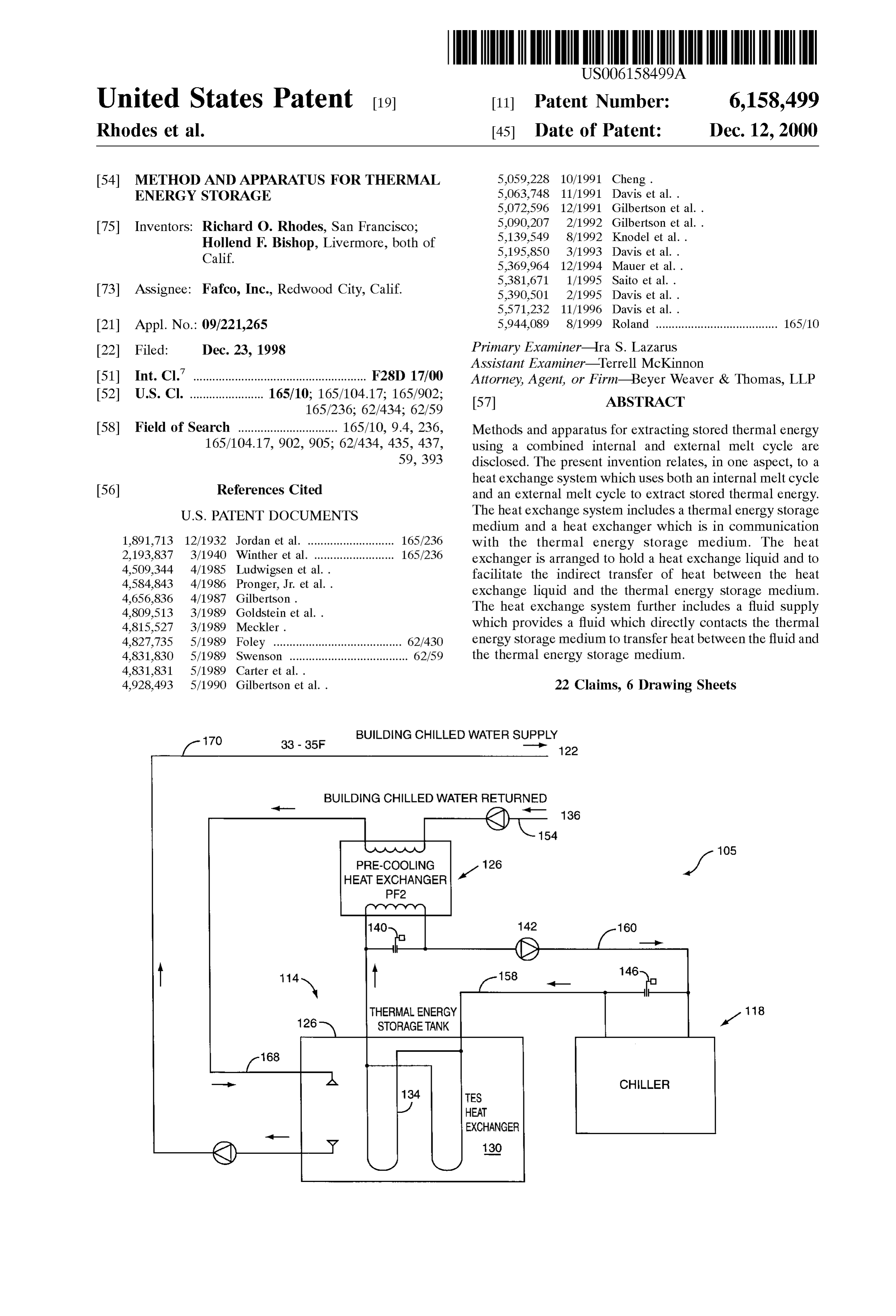
170 BUILDING CHILLED WATERSUPPLY 33 - 35F 122
BUILDING CHILLED WATER RETURNED
HEAT EXCHANGER
THERMAL ENERGY 118
STORAGETANK A1
CHILLER
TES
HEAT
EXCHANGER
Page 2
Drawing sheet — no readable text.
Page 3
Drawing sheet — no readable text.
Page 4
Drawing sheet — no readable text.
Page 5
Drawing sheet — no readable text.
Page 6
Drawing sheet — no readable text.
Page 7
Drawing sheet — no readable text.
Page 8
METHOD AND APPARATUS FOR THERMAL tendency to become more inefficient as the ice melts. That is, ENERGY STORAGE the performance of the internal melt cycle decreases during
BACKGROUND OF THE INVENTION
the course of the cycle.
Another melt cycle which is often used to melt a thermal 1. Field of Invention energy Storage medium is an external melt cycle. An exter The present invention relates generally to thermal energy nal melt cycle involves circulating a fluid, which is to be Storage Systems. More particularly, the present invention used as part of a cooling System, Such that the fluid comes relates to thermal energy Storage Systems which utilize a into direct contact with the thermal energy Storage medium, combined internal melt and external melt cycle. which is typically ice. The fluid, which is cooled as the ice 2. Description of the Related Art melts, as well as run-off from the melted ice, is used as the Thermal energy Storage (TES) systems are used to Store cooling medium within a cooling System. For an external thermal energy for use at a later time for heating or cooling melt may cycle, although the cooling fluid used to melt the ice be any of a number of different Substances, the cooling processes. For example, the use of TES Systems enables fluid is typically water.
electricity at off-peak demand hours to be used to freeze ice. 15
The frozen ice may then be melted during peak electricity AS the cooling fluid is in direct contact with the ice during demand hours to provide cooling capabilities without Sig an external melt cycle, the fluid is generally at a temperature nificant usage of electricity during the peak demand hours. which is close to the temperature of the ice. AS Such, the That is, TESSystems are typically arranged to use electricity thermal performance of a TES System which uses an exter at off-peak energy demand periods to “store' energy for use nal melt cycle is generally better than the performance during peak energy demand periods. AS the efficient use of which is typically achieved with a TES system which uses energy becomes more of a concern, the use thermal energy the internal melt cycle described above. However, in order Storage (TES) systems is becoming increasingly popular. to use an external melt System, a tank that is used to house Heat eXchangers are generally included as a part of a TES the ice must be sized to accommodate the flow of fluid over System. A heat eXchanger may be arranged, for example, 25 SZC. the ice. AS Such, leSS ice may be formed in a tank of a given Such that cooling liquid may be pumped through the heat eXchanger to Store energy in a thermal energy Storage Further, uniform ice melt is often difficult to achieve in an medium. Such “cold energy Storage is accomplished external melt System. In order to uniformly melt the ice Such through cooling the thermal energy Storage medium. The that consistency and, therefore, efficiency in the thermal thermal energy Storage medium is typically in the form of performance of the TES system is maintained, high flow either a low-temperature fluid or a Solid Such as ice, and is rates for the fluid are often required. In addition, a variety of in contact with the heat eXchanger. After energy is Stored in controls and Sensors are typically used to detect undesirable the thermal energy Storage medium, at a later time, the ice build-up, e.g., bridging, which often occurs when ice is thermal energy Storage medium is used to provide chilled air not uniformly melted. Such controls and sensors are both for cooling purposes, as will be appreciated by those skilled 35 expensive and difficult to maintain. However, without the in the art. For example, the chilled air may be used as a part controls and Sensors, bridging in the ice often causes ice to of an air-conditioning System that is arranged to cool a be non-uniformly and, therefore, inefficiently melted. building. The utility of TES systems is often limited by the perfor Melt cycles are used to melt the thermal energy Storage mance of the TES systems, as well as by the cost of Such medium to provide a cooled fluid that may be used as part 40 Systems, and the complexity of controls and Sensors that are of a cooling System. One melt cycle that is often used to melt needed to maintain Such Systems. AS the importance of the a thermal energy Storage medium is an internal melt cycle. efficient use of energy increases, the potential use of TES An internal melt cycle involves melting the thermal energy Systems also increases. Hence, the ability to provide Storage medium, e.g., ice, by allowing a heat eXchange fluid efficient, relatively inexpensive, and easy to maintain TES to come into indirect contact with the ice. By way of 45 Systems is desirable. Therefore, what is desired are methods example, a heat eXchange fluid which is at a higher tem and apparatus for efficiently providing cooled fluid to a perature than the ice may be pumped through pipes, or cooling System that is a part of an overall TES System. enclosed pathways, which are in contact with the ice. AS the SUMMARY OF THE INVENTION heat eXchange fluid is pumped through the pipes, the ice melts, and the heat eXchange fluid cools. The cooled heat 50 The present invention relates, in one aspect, to a heat eXchange fluid is then used as part of a cooling System that eXchange System which uses both an internal melt cycle and is associated with the TES system. an external melt cycle to extract Stored thermal energy. The Although an internal melt cycle Serves the purpose of heat eXchange System includes a thermal energy Storage providing a cooled heat eXchange fluid that may be used as medium and a heat eXchanger which is in communication part of a cooling System, the use of an internal melt cycle is 55 with the thermal energy Storage medium. The heat not always efficient. Specifically, the heat eXchange fluid eXchanger is arranged to hold a heat eXchange liquid and to flows through a pipe and, therefore, does not come into facilitate the indirect transfer of heat between the heat direct contact with the ice. Accordingly, the overall heat eXchange liquid and the thermal energy Storage medium. transfer between the ice and the heat eXchange fluid is The heat eXchange System further includes a fluid Supply affected by both the pipe and the Space created between the 60 which provides a cooling fluid which directly contacts the pipe and the ice as the ice melts. Hence, both the rate at thermal energy Storage medium to transfer heat between the which the ice melts, as well as the amount of cooling which cooling fluid and the thermal energy Storage medium. can occur in the heat eXchange fluid, are affected. Further, In one embodiment, the heat eXchanger includes a plu the Space between the pipe and the ice increases as the ice rality of heat eXchange tubes that are arranged to allow the melts. Thus, both the ability for the ice to melt and the ability 65 heat eXchange liquid to flow therethrough. In another for the heat eXchange fluid to be cooled decreases. embodiment, the heat eXchange System is in communication Therefore, the performance of the TES system has the with a cooling System that uses the heat eXchange liquid to
Page 9
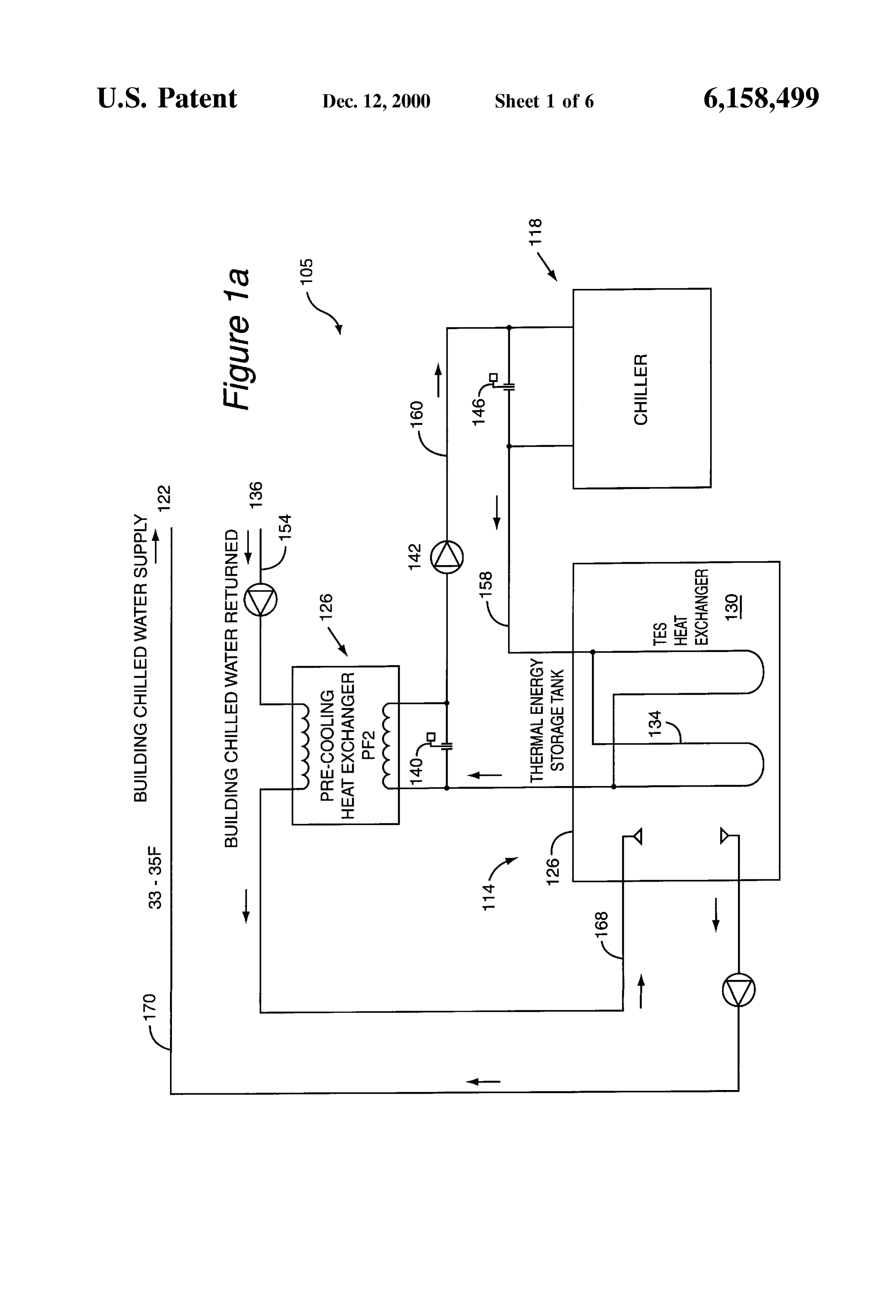
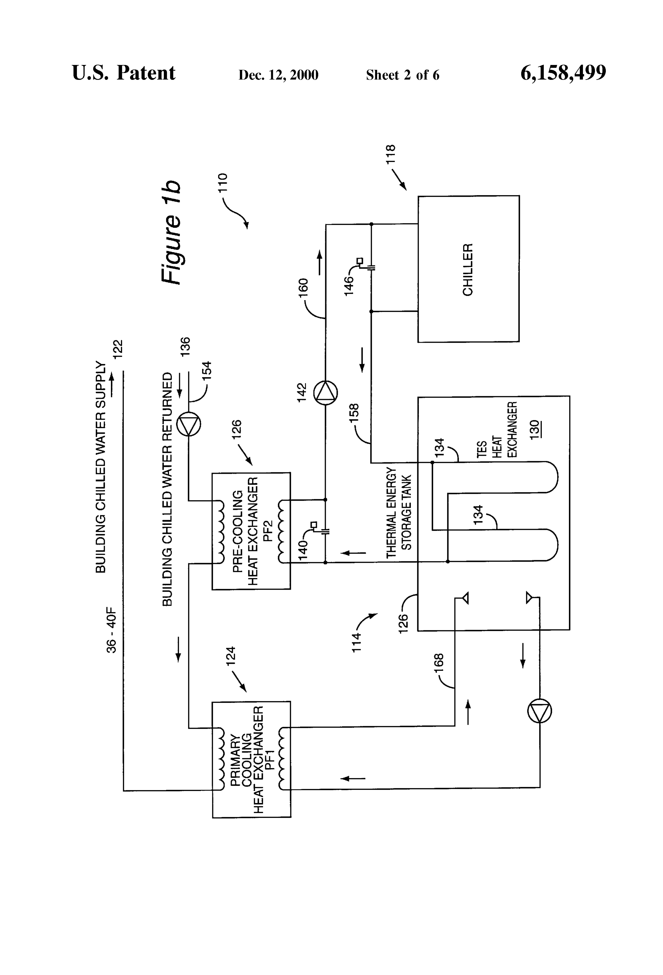
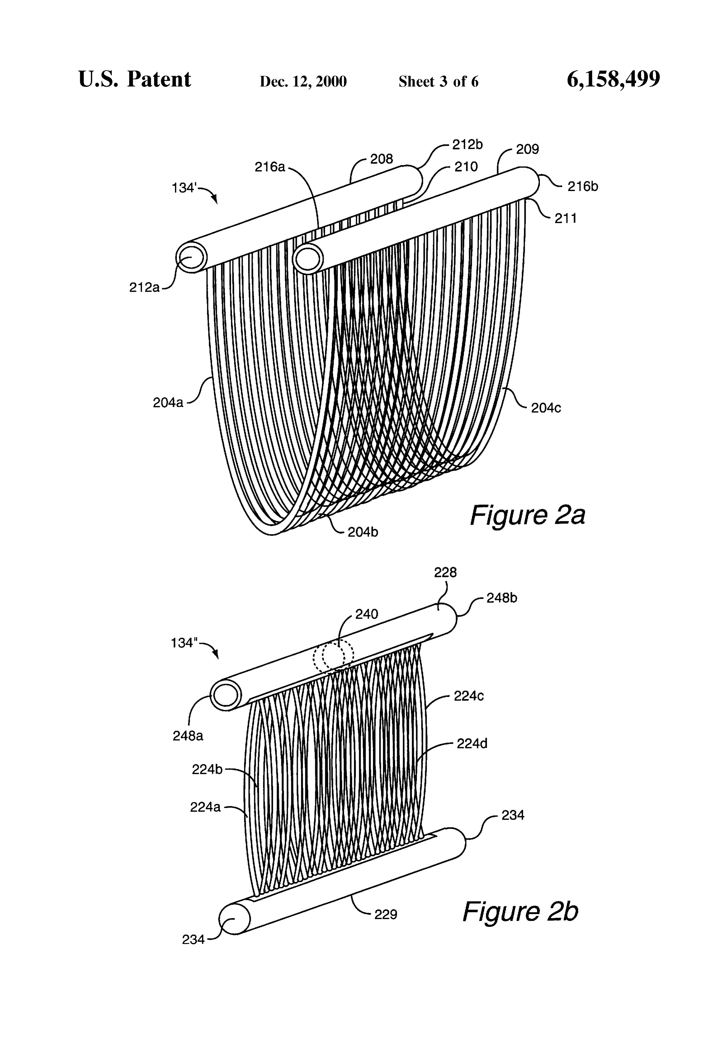
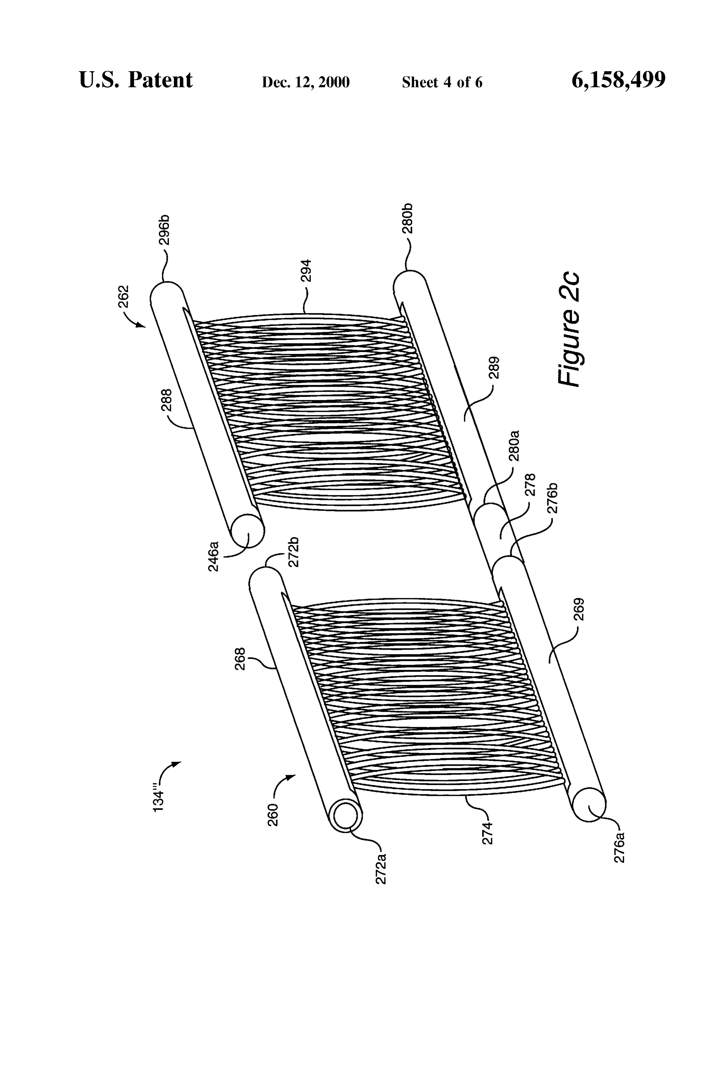
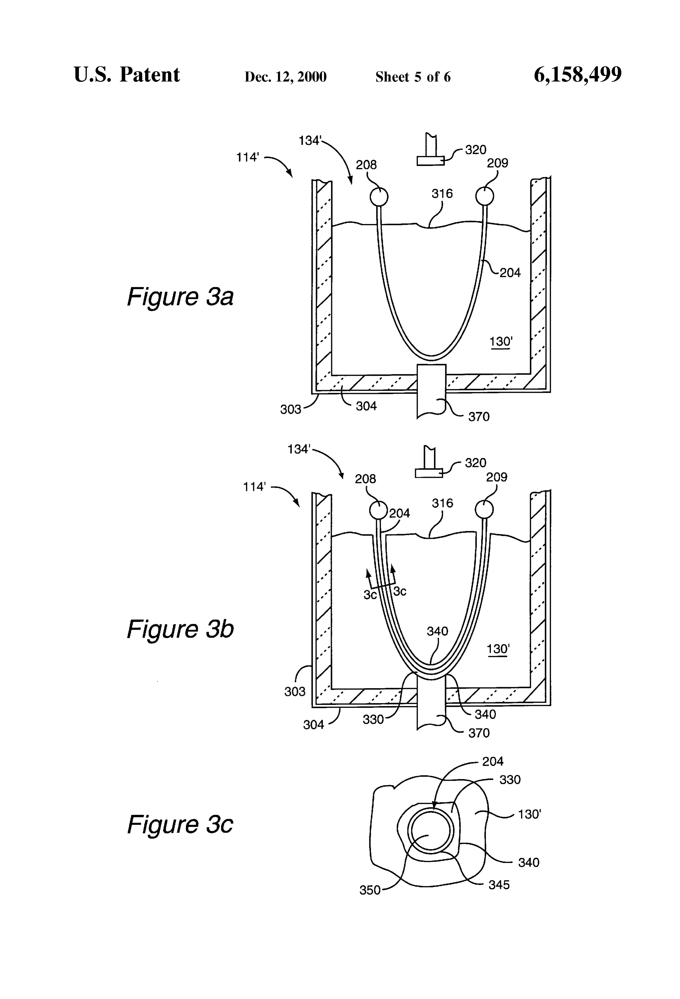
generate chilled air. In Such an embodiment, the cooling FIG. 1b is a diagrammatic block representation of a System may also be arranged to use the cooling fluid in the closed-loop thermal energy storage (TES) System in accor generation of chilled air. dance with an embodiment of the present invention. According to another aspect of the present invention, a FIG. 2a is a diagrammatic representation of a first con method for extracting thermal energy Stored as a Substan figuration of a heat eXchanger in accordance with an tially frozen Substance involves at least partially melting the embodiment of the present invention. frozen Substance using a first melting process. The first FIG. 2b is a diagrammatic representation of a Second melting proceSS is arranged to cause a channel to be formed configuration of a heat eXchanger in accordance with an in the frozen Substance. The method further involves at least embodiment of the present invention. partially melting the frozen Substance using a Second melt 1O FIG. 2c is a diagrammatic representation of a third ing process that is facilitated by the channel formed in the configuration of a heat eXchanger in accordance with an frozen Substance. In one embodiment, the Substantially embodiment of the present invention.
frozen Substance is frozen around at least a portion of a heat FIG. 3a is a diagrammatic cross-sectional Side view of a eXchanger, and the channel is formed around the portion of first thermal energy Storage unit prior to a melt cycle in the heat eXchanger. In Such an embodiment, a first Substance 15 accordance with an embodiment of the present invention. is circulated through the portion of the heat eXchanger, Such FIG.3b is a diagrammatic cross-sectional side view of the that the first Substance is cooled as the channel is formed.
Further, in Such an embodiment, a Second Substance is run first thermal energy Storage unit of FIG. 3 a after an initial over the frozen Substance Such that the Second Substance is internal melt process in accordance with an embodiment of substantially in contact with the frozen substance. The the present invention.
Second Substance is also run through the channel, and is FIG.3C is a diagrammatic cross-sectional view of the area cooled by contact with the frozen Substance. around a heat eXchange tube after an internal melt process According to Still another aspect of the present invention, taken along line 3c-3c of FIG. 3b in accordance with an a thermal energy Storage System includes a holding tank embodiment of the present invention.
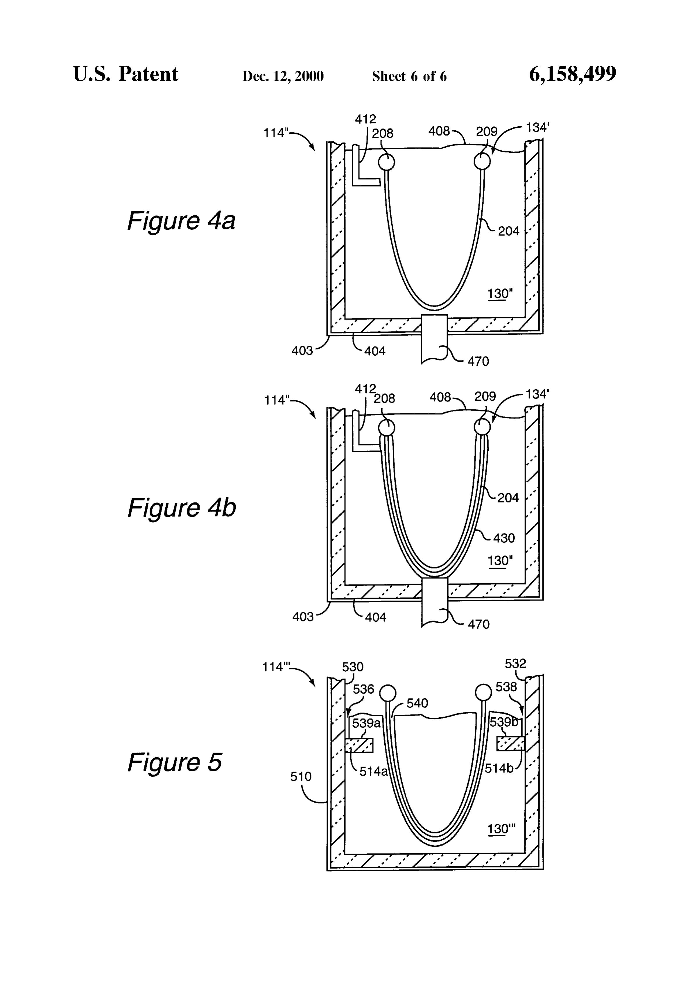
which is arranged to hold a thermal energy Storage medium FIG. 4a is a diagrammatic cross-sectional Side view of a and has an inlet and an outlet. Within the holding tank, a heat 25 Second thermal energy Storage unit prior to a melt cycle in eXchanger, which is arranged to indirectly transfer heat accordance with an embodiment of the present invention. between a heat eXchange fluid that passes through the heat FIG. 4b is a diagrammatic cross-sectional Side view of the eXchanger and the thermal energy Storage medium, is posi Second thermal energy Storage unit of FIG. 4a after an initial tioned. The holding tank is coupled to a chiller that is internal melt process in accordance with an embodiment of arranged to cool the heat eXchange fluid, and a cooler which the present invention.
is arranged to generate chilled air using a cooling fluid. The FIG. 5 is a diagrammatic croSS-Sectional Side view of a thermal energy Storage System also includes a first heat thermal energy Storage unit with baffling in accordance with eXchanger Supply loop for delivering cooled heat eXchange another embodiment of the present invention. fluid from the chiller to the heat eXchanger and for returning DETAILED DESCRIPTION OF THE the heat eXchange fluid from the heat eXchanger to the chiller 35 EMBODIMENTS after the heat eXchange fluid passes through the heat eXchanger. A holding tank Supply loop within the thermal Conventional Thermal Energy Storage (TES) systems are energy Storage System is arranged to deliver cooling fluid often either, or both, inefficient and expensive. In particular, from the cooler to the holding tank such that when the internal melt cycles, which are used to melt a thermal thermal energy Storage medium is present, the delivered 40 Storage medium are inconsistent with regards to efficiently cooling fluid directly contacts the thermal energy Storage producing cooled Substances which may be used as a part of medium. The holding tank Supply loop is further arranged to a cooling System. On the other hand, from a performance return the cooling fluid from the holding tank to the cooler. Standpoint, external melt cycles that are used to melt a A Second heat eXchanger Supply loop is arranged to deliver thermal Storage medium are more consistent than internal warmed heat eXchange fluid to the heat eXchanger. 45 melt cycles. However, the implementation of external melt The thermal energy Storage System is further arranged to cycles is generally expensive and, hence, often considered to cause the thermal energy Storage medium to cycle between be inefficient as well.
Solid and liquid phases to facilitate the Storage of energy. The present invention Seeks to combine desirable qualities When the thermal energy Storage medium is in a Solid phase, of internal melt and external melt cycles to provide a TES the heat eXchange fluid delivered through the Second heat 50 System with good performance at a reasonable cost. In the eXchanger Supply loop may be used to form channels in the described TES System, a thermal Storage medium is cooled, thermal energy Storage medium via an internal melt proceSS e.g., frozen, and an internal melt cycle is used to form flow to facilitate more even melting of the thermal energy Storage channels in the thermal storage medium. While flow chan medium during an external nels are being formed using the internal melt process, heat melt process utilizing cooling fluid delivered through the 55 eXchange fluids used in the internal melt process are cooled. holding tank Supply loop. Once flow channels are formed, an external melt cycle is These and other advantages of the present invention will implemented, either alone or in conjunction with the internal become apparent upon reading the following detailed melt cycle, to further provide cooled fluid for use with a description and Studying the various figures of the drawings. cooling System. Fluid flow during the external melt cycle is 60 primarily through the flow channels produced during the
BRIEF DESCRIPTION OF THE DRAWINGS
internal melt cycle. The flow channels are typically Substan
The invention may best be understood by reference to the tially uniform, and have a relatively large Surface area, following description taken in conjunction with the accom which generally enables cooling to be maximized. Since the panying drawings in which: Surface area of the flow channels is relatively large, the flow FIG. 1a is a diagrammatic block representation of an 65 rate of the cooling fluid used in the external melt process to open-loop thermal energy Storage (TES) system in accor melt the thermal energy Storage medium may be kept dance with an embodiment of the present invention. relatively low.
Page 10
S 6
Referring initially to FIG. 1a, a TES system will be An external melt cycle, or process, involves cooling a heat described in accordance with an embodiment of the present eXchange fluid, or any other fluid, e.g., water, by allowing invention. A TES system 105 typically includes an energy the fluid to directly contact thermal energy Storage medium Storage unit 114, a chilling unit 118, a cooler unit 122, and 130. Direct contact between the fluid and thermal energy a water Supply 136. Energy Storage unit 114 includes an storage medium 130 facilitates the exchange of heat between enclosure 126 which holds a thermal energy Storage medium the fluid and thermal energy storage medium 130. Such a 130. Energy Storage unit 114 also includes a heat eXchanger fluid may be provided from water supply 136 which is 134 which is in contact with thermal energy Storage medium positioned to allow fluid to flow over thermal energy Storage 130, and a pre-cooling heat eXchanger 126. Although heat eXchanger 134 may take on a variety of different forms, three medium 130. As the fluid flows through a line 168, then over and around thermal energy Storage medium 130, thermal particularly Suitable configurations of heat eXchanger 134 energy Storage medium 130 typically melts, or otherwise will be described below with respect to FIGS. 2a-2c. “warms up”. Due to the fact that the fluid is in direct contact When energy rates are relatively low, e.g., during off-peak with thermal energy Storage medium 130, the temperature of energy demand periods, thermal energy Storage medium 130 the fluid, once the fluid is cooled by the thermal energy is cooled by pumping a heat eXchange liquid through chiller 15 Storage medium 130, is generally only a few degrees above 118. Chiller 118 is a part of an overall source of heat the freezing, or chilled, temperature of thermal energy eXchange liquid. From chiller 118, the heat eXchange liquid storage medium 130.
is pumped through a line 158 heat exchanger 134. It should Once fluid provided by water supply 136 is allowed to be appreciated that Suitable heat eXchange liquids may be flow over and around thermal energy storage medium 130 to widely varied and include, by way of example, propylene at least partially melt thermal energy Storage medium 130, glycol and ethylene glycol. the fluid, as well as melted portions of thermal energy The heat eXchange liquid may be returned from heat Storage medium 126, may be extracted from within pre exchanger 134 to chiller 118 through a line 160, bypass cooling heat eXchanger, or enclosure, 126 through a line 170. Valve 140, and pump 142, without passing through pre Once extracted, or drained out of enclosure 126, the fluid cooling heat eXchanger 126. By cooling thermal energy 25 and melted portions of thermal
Storage medium 130, energy is Stored in thermal energy may be provided to cooler 122 energy Storage medium 126 storage medium 130. It should be appreciated that although the generation of chilled, or cooled, air. line 170 for use in through thermal energy Storage medium 130 may be any Substance By increasing the Surface area of thermal energy Storage which is capable of maintaining a chilled temperature, in one medium 130 which comes into direct contact with fluid embodiment, thermal energy Storage medium 130 is a Sub during stance which undergoes a phase change when the Substance thermalanenergy external melt process, the thermal performance of Storage unit 114 is typically improved, as is chilled. By way of example, one particularly Suitable more of thermal
Substance is water. Water undergoes a phase change from Further, the uniformity energy Storage medium 130 may be melted. liquid form to ice when Substantially chilled, i.e., when medium 130 is melted iswith which thermal energy storage also improved by increasing the frozen at approximately Zero degrees Centigrade or leSS. 35
During times when energy rates are higher, e.g., during comes into contact with fluid, as Storage Surface area of thermal energy will be medium 130 which appreciated by those peak energy demand periods, and chilled water is desired, skilled in the art.
Stored energy may be extracted from thermal energy Storage unit 114. When energy is to be extracted from thermal To increase the Surface area of thermal energy Storage energy Storage unit 114, Stored energy is extracted using a 40 medium 130, or, more particularly, to increase the Surface combination of an internal melt proceSS and an external melt area with respect to the overall Volume of thermal energy process. An internal melt cycle, or process, involves Storage medium 130, both an internal melt cycle and an enabling thermal energy Storage medium 130 to exchange external melt cycle may be implemented. By way of heat with a heat eXchange liquid without direct contact being example, an internal melt cycle may be used to create flow made between thermal energy Storage medium 130 and the 45 channels which may be used during an external melt cycle. heat eXchange liquid. By way of example, the heat eXchange Specifically, the creation of flow channels using an internal liquid, which is generally the same heat eXchange liquid that melt cycle provides additional Surface area on thermal is used to cool thermal energy Storage medium, is pumped energy storage medium 130 which may be contacted by fluid through line 158 to heat exchanger 134, bypassing chiller provided during an external melt cycle, as will be described 118 through valve 146. Pumping the heat exchange liquid 50 below with respect to FIGS. 3a–3c.
through heat eXchanger 134 cools, or chills, the heat As mentioned above, FIG. 1a shows an open-loop TES eXchange liquid and enables portions of thermal energy System. AS will be appreciated by those skilled in the art, a storage medium 130 to be melted. Once the heat exchange TES system may also be closed-loop. FIG. 1b is a diagram liquid is chilled, the chilled heat eXchange liquid is then matic block representation of a closed-loop TES System in pumped through a pre-cooling heat eXchanger 140, to pro 55 accordance with an embodiment of the present invention. A vide chilled water for use, for example, in air-conditioning closed-loop TES system 110 is similar to open-loop TES a building. It should be appreciated that the melted portions system 105 of FIG.1a. One difference between TES system of thermal energy Storage medium 130 may also be pumped 110 and TES system 105 of FIG. 1a is that TES system 110 through a heat eXchanger. uses a primary cooling heat eXchanger 124 to cool the In general, the use of the building chilled water Supply to 60 chilled water return from the external melt. Specifically, in generate chilled air results in the heating of heat eXchange the embodiment as shown, TES system 105 utilizes a liquid. The heated heat eXchange liquid may be circulated primary cooling heat eXchanger 124 in addition to pre back through a line 154 to pre-cooling heat eXchanger 126. cooling heat eXchanger 126.
In Some embodiments, the heated heat eXchange liquid may Heat eXchanger 134, as previously mentioned, may take be cooled by chiller 118 and heat exchanger 134. In other 65 any suitable form. With reference to FIG. 2a, one embodi embodiments, the heated heat eXchange liquid may be ment of a heat eXchanger for use in a TES System with a cooled by Substantially only heat exchanger 134. combined internal and external melt process will be
Page 11
described. That is, one embodiment of heat exchanger 134 merged in a thermal energy Storage medium, issues related of FIG. 1 will be described. Heat exchanger 134 is consid to "plumbing,” or the arrangement of pipes used to transport ered to be a “bent' heat eXchanger, as heat eXchange tubes flow of heat exchange liquid to and from header pipes 208, 204 of heat exchanger 134 are formed into a substantially 209, may be avoided. That is, access to header pipes 208, U-shaped configuration. Heat eXchange tubes 204 may be 209 may be maintained substantially above the surface of a made from any Suitable material. By way of example, heat thermal energy Storage medium in which heat eXchanger eXchange tubes 204 may be made from thermoplastic mate 134 is located, thereby facilitating access to header pipes rials which include, but are not limited to, polyolefins Such 208, 209.
as polypropylene and polyethylene. In one embodiment, FIG. 2b is a diagrammatic representation of a Second heat eXchange tubes 204 may be made from a dark, ther configuration of a heat eXchanger in accordance with an moplastic material. embodiment of the present invention. A “straight' or panel The dimensions of heat exchange tubes 204, as well as the like heat exchanger 134", like heat exchanger 134 described number of heat exchange tubes 204 included in heat above with respect to FIG. 2a, is composed of an array of eXchanger 134, may be widely varied depending upon the heat eXchange tubes 224 that are coupled to header pipes requirements of a particular TES application. In the 15 228, 229. Heat exchange tubes 224 are arranged such that described embodiment, the Outer diameter of heat eXchange individual heat eXchange tubes 224, e.g., heat eXchange tubes 204 is in the range of approximately 0.2 to approxi tubes 224a and 224b, are Substantially adjacent to and mately 0.5 inches, as for example approximately 0.25 parallel with one another. Spacers (not shown) may be used inches, while the inner diameter for heat exchange tubes 204 to maintain Space between adjacent heat eXchange tubes 224 may vary from approximately 0.15 inches to approximately Such that portions of a thermal energy Storage medium may 0.45 inches, as for example approximately 0.2 inches. The be frozen Substantially around each heat eXchange tube 224. length of heat eXchange tubes 204 may range from approxi mately 80 inches in length to approximately 220 inches in Heat eXchange tubes 224, in the described embodiment, are length. formed from a thermoplastic material, as for example Heat eXchange tubeS 204 are arranged in an array Such polypropylene and polyethylene. A heat eXchange fluid may that tubes 204 are substantially parallel and adjacent to one 25 flow from header pipe 228, which is generally arranged to be another. In general, heat eXchange tubes 204 are held Such coupled to a Supply of heat eXchange fluid, through heat that contact between adjacent tubes 204 is minimal. In order eXchange tubes 204. AS the heat eXchange fluid flows, an to maintain minimal contact between adjacent heat eXchange internal melt process enables heat transfer to occur “indi tubes 204, Spacers (not shown) may be included as part of rectly between the heat eXchange liquid and the thermal heat eXchanger 134 for the purpose of holding heat energy Storage medium that is frozen around heat eXchange eXchange tubes 204 Substantially apart. When heat eXchange tubes 224. That is, heat eXchange occurs through heat tubes 204 are held Substantially apart, a thermal energy exchange tubes 204.
storage medium may be frozen around tubes 204. Heat Heat exchanger 134" is arranged Such that when heat exchange tubes 204 are attached to header pipes 208, 209. eXchanger 134" is at least partially Submerged in a thermal Specifically, opposite ends of heat eXchange tubes 204 are 35 energy Storage medium, header pipe 229 is Submerged in the coupled to different header pipes 208, 209, e.g., a first end thermal energy Storage medium. AS Such, due to the fact that 210 and a second end 211 of heat exchange tube 204c are access, e.g., plumbing access, to header pipe 229 is prefer coupled to header pipe 208 and header pipe 209, respec ably substantially above or near the Surface of the thermal tively. Header pipe 208 is arranged to be coupled to a Supply energy Storage medium, heat eXchanger 134" may be con of heat eXchange fluid, Such that a heat eXchange fluid may 40 figured Such that plumbing access to header pipe 229 is flow through header pipe 208 and into heat exchange tubes generally unnecessary.
204. The heat exchange fluid then flows through heat In the described embodiment, the ends 234 of header pipe exchange tubes 204, to header pipe 209, which is generally 229 are capped, and the flow of heat eXchange fluid is coupled to a cooling System, e.g., cooler 122 of FIG. 1. channeled "down” Some heat eXchange tubes 224, e.g., heat In general, header pipe 208 is open at a first end 212a to 45 exchange tubes 224a and 224b, through header pipe 229, enable a heat eXchange fluid to flow therethrough. However, and back "up' through other heat eXchange tubes 224, e.g., in order to essentially “force” the heat exchange fluid to flow heat exchange tubes 224c and 224d. That is, a loop for the through heat eXchange tubes 204, in one embodiment, a flow of a heat eXchange liquid is formed in heat eXchanger second end 212b of header pipe 208 is usually capped. 134". Such a loop enables access, e.g., plumbing access, to Similarly, a first end 216a of header pipe 209 is open to 50 heat exchanger 134" to be substantially limited to header enable heat exchange fluid to flow through header pipe 209 pipe 228. In order to form a loop for the flow of a heat to an cooling System, whereas a Second end 216b of header eXchange liquid, a block 240 may be placed within header pipe 209 is capped to constrain the heat eXchange fluid to pipe 240 to prevent the heat exchange fluid from flowing flow towards first end 216a. directly from a first end 248a to a second end 248b of header Heat eXchanger 134" may be arranged Such that only 55 pipe 228, which are both open in the described embodiment. portions of heat eXchange tubes 204 are Submerged in a That is, as first end 248a and second end 248b are open, thermal energy Storage medium, as will be discussed below block 240 may be used to form a barrier within header pipe with reference to FIG.3a. In other words, a thermal energy 228 to facilitate the flow of heat exchange fluid through heat Storage medium may be frozen around only portions of heat eXchange tubes 224, as will be appreciated by those skilled exchange tubes 204. Alternatively, heat exchanger 134" may 60 in the art.
be arranged Such that heat eXchanger 134 is Substantially With reference to FIG.2c, a third configuration of a heat Submerged in a thermal energy Storage medium Such that a eXchanger will be described in accordance with an embodi thermal energy Storage medium may be frozen around most, ment of the present invention. A heat eXchanger 134" may if not all, of heat exchange tubes 204, as will be described be considered to be a coupled panel heat eXchanger, as heat below with respect to FIG. 4a. 65 eXchanger 134" is essentially composed of two panel heat AS heat eXchanger 134 may be arranged Such that neither eXchangers, which are similar to heat eXchanger 134" of header pipe 208 nor header pipe 209 is necessarily Sub FIG.2b. Heat exchanger 134" includes a first panel 260 and
Page 12
a second panel 262. A first header pipe 268 of panel 260 is 204 that are Submerged in thermal energy Storage medium open at a first end 272a and capped at a Second end 272b, 130'. When thermal energy storage medium 130' is frozen, Such that the flow of heat eXchange fluid through heat thermal energy is Stored in thermal energy Storage medium eXchange tubes 274 is facilitated. That is, heat eXchange 130'.
fluid, which flows into first end 272a and through first Although thermal energy Storage medium 130' may be header pipe 268, is further essentially forced to flow through chilled or frozen using any Suitable process, in the described heat exchange tubes 274. embodiment, a heat eXchange fluid is circulated through heat A second header pipe 269 of first panel 260 is capped at eXchanger 134 to freeze thermal energy Storage medium a first end 276a, and is open at a second end 276b. An 130'. The heat exchange fluid will generally be at a tem extension pipe 278 is coupled to second end 276b of second perature that is low enough Such that heat transfer from the header pipe 269 of first panel 260, as well as to an open first heat eXchange fluid through heat eXchange tubeS 204 to end 280a of a second header pipe 289 of second panel 262. thermal energy Storage medium 130' is enough to promote A second end 280b of second header pipe 289 of second cooling and, eventually, freezing of thermal energy Storage panel 262 is capped. AS Such, any heat eXchange fluid which medium 130'. By way of example, if thermal energy storage flows through second header pipe 269 of first panel 260 then 15 medium 130' is water, as water freezes at a temperature of flows through extension pipe 278 and Second header pipe approximately Zero degrees Centigrade, a heat eXchange 289 of second panel 262. The heat exchange fluid then flows fluid at a temperature that is lower than approximately Zero up through heat eXchange tubes 294 of Second panel, and degrees Centigrade will typically promote the freezing of the into a first header pipe 288 of second panel 262. A first end Water.
296a of first header pipe 288 of second panel 262 is capped, In one embodiment, thermal energy Storage medium 130 while a second end 296b of first header pipe 288 of second may be completely frozen within holding tank 303. panel 262 is open. Hence, heat eXchange fluid may exit heat However, it should be appreciated that in other exchanger 134" through second end 296b of first header embodiments, Some portions of thermal energy Storage pipe 288 of second panel 262. medium 130' may be frozen while other portions remain In general, when heat eXchanger 134" is in use, header 25 Substantially liquid. Specifically, portions of thermal energy pipes 269 and 289 are submerged beneath the surface of a Storage medium 130' which are closest to heat eXchanger thermal energy Storage medium. AS Such, as previously 134" may be frozen, while outlying portions of thermal described, plumbing access to header pipes 269 and 289, energy Storage medium 130', or portions of thermal energy although possible, is less desirable than plumbing access to storage medium 130' that are further from heat exchanger header pipes 268 and 288, which are generally either above 134, may remain Substantially liquid. In general, as will be or near the Surface of the thermal energy Storage medium. appreciated by those skilled in the art, by varying the By enabling heat eXchange fluid to enter heat eXchanger duration of a thermal energy Storage process, e.g., a freezing 134" from first header pipe 268 of first panel 260 and exit process, the size of the frozen portions of thermal energy heat exchanger 134" through first header pipe 288 of second storage medium 130' may be controlled. panel 262, plumbing access to heat eXchanger 134" is 35 FIG. 3b is a diagrammatic cross-sectional side view of generally maintained Substantially above the Surface of the thermal energy storage unit 114 of FIG. 3a after an initial thermal energy Storage medium. internal melt process in accordance with an embodiment of In order to promote a transfer of heat between a heat the present invention. An internal melt process is used to eXchanger or, more Specifically, a heat eXchange fluid which melt a flow channel 330 in thermal energy storage medium runs through the heat eXchanger, and a thermal energy 40 130' around substantially each heat exchange tube 204 in Storage medium, the heat eXchanger is typically placed in heat exchanger 134. In the described embodiment, the contact with the thermal energy Storage medium. Referring internal melt process involves circulating a heat eXchange next to FIG. 3a, one orientation of a heat eXchanger with fluid through heat exchanger 134. Heat transfer between respect to a thermal energy Storage medium will be thermal energy Storage medium 130' and the heat eXchange described. In particular, one orientation of heat eXchanger 45 fluid that is circulating through heat eXchanger 134 or, more 134 of FIG.2a will be described. FIG.3a is a diagrammatic specifically, heat exchange tube 204, causes channel 330 to croSS-Sectional representation of a thermal energy Storage be formed around heat exchange tube 204, as will be unit prior to a melt cycle in accordance with an embodiment described below with respect to FIG. 3c. It should be of the present invention. Thermal energy Storage unit 114 appreciated that during the internal melt process, the heat includes a holding tank 303 which, as shown, has an 50 eXchange fluid is cooled while at least portions of thermal insulating layer 304 which is arranged to insulate a thermal energy Storage medium 130', particularly portions which are energy Storage medium 130', e.g., water, contained within in close proximity with heat eXchange tube 204, are melted. holding tank 303. It should be appreciated that although The chilled heat eXchange fluid is generally used as part of holding tank 303 may be used to enclose thermal energy a cooling System that generates chilled air. storage medium 130' without the benefit of insulating layer 55 The melted portions of thermal energy Storage medium 304, the inclusion of insulating layer 304 increases the 130' may be drained from thermal energy storage unit 114 overall efficiency of thermal energy Storage unit 114". using a draining mechanism 370 situated within thermal Although insulating layer 304 may be made from any energy Storage unit 114'. It should be appreciated that the Suitable material, in one embodiment, insulating layer 304 is draining mechanisms are typically coupled to the cooling made from foam insulation. 60 System Such that the melted portions of thermal energy AS Shown, heat eXchanger 134 is oriented Such that Storage medium 130' may also be used as part of the cooling header pipes 208 and 209 are above a top surface 316 of System to generate chilled air. In one embodiment, draining thermal energy Storage medium 130' to facilitate access to mechanisms may be arranged to drain the melted portions of header pipes 208 and 209 from, for example, a source of heat thermal energy Storage medium 130' from near top Surface exchange fluid (not shown). As shown, thermal energy 65 316 of thermal energy storage medium 130'. In another Storage medium 130' is frozen around heat eXchange tube embodiment, as shown, draining mechanism 370 may be 204 or, more specifically, the portions of heat eXchange tube located such that draining mechanism 370 is in communi
Page 13
cation with channel 330 and is arranged to drain melted may be located in any suitable portion of holding tank 303, portions of thermal energy Storage medium 130' from chan as previously described. Further, the draining mechanism nel 330. may take on any number of different forms. By way of It should be appreciated that for embodiments in which example, the draining mechanism may include a pipe which only portions of thermal energy Storage medium 130' are draws the run-off from a localized area of holding tank 303, initially frozen prior to an internal melt process, when such as one side of holding tank 303. Alternatively, the channel 330 is created during an internal melt process, draining mechanism may be arranged to draw the run-off channel 330 may be in communication with unfrozen, i.e., over different areas of holding tank 303. For example, the liquid, portions of thermal energy Storage medium 130'. By draining mechanism may be arranged to draw the run-off way of example, the bottom of channel 330 may open into from locations near the bottom of holding tank 303 and an unfrozen portion of thermal energy Storage medium 130'. locations near top Surface 316 of thermal energy Storage In Such embodiments, draining mechanisms may be added medium 316.
near the interior bottom of holding tank 303 to drain melted In one embodiment, the internal melt proceSS is allowed portions of thermal energy Storage medium 130'. to continue even after the external melt proceSS has been Once channel 330, or a “melt-Zone”, is formed using an 15 implemented. By enabling the internal melt process to internal melt process, an external melt process is typically continue, the cooling System linked to thermal energy Stor implemented to continue the melting of thermal energy age unit 114 is provided with cooled heat eXchange fluid in storage medium 130'. That is, after an internal melt process addition to run-off, and may, therefore, produce a larger is used to establish a flow path, or paths, in thermal energy amount of chilled water than would be produced if only the Storage medium 130', an external melt proceSS is used to run-off were used in the production of chilled air. In another melt Substantially the remainder of thermal energy Storage embodiment, the internal melt proceSS is stopped once the medium 130'. The external melt process may be imple external melt process is implemented. The efficiency of the mented at any time after channel 330 is formed. However, heat transfer between a heat eXchange fluid circulating the external melt process is typically not implemented until 25 through heat eXchanger 134 and thermal energy Storage channel 330 has an axial dimension that is large enough to medium 130' typically decreases as thermal energy Storage accommodate the flow of water therethrough, around heat medium 130' melts, due to the fact that as thermal energy exchange tube 204. In one embodiment, the external melt storage medium 130' melts, the axial dimension of channel process begins when the axial dimension of channel 330 is 330 increases. AS Such, in Some Systems, the use of an approximately twice the Size of the outer diameter of heat external melt proceSS alone, after an initial internal melt eXchange tube 204. Although the diameter of heat eXchange process, may be preferred over the use of both processes tube 204 may be widely varied, in the described Simultaneously, after an initial internal melt proceSS. embodiment, the outer diameter of heat exchange tube 204 FIG.3C is a diagrammatic cross-sectional view of the area is in the range of approximately 0.2 to approximately 0.5 around a heat exchange tube after an internal melt process in inches, as for example approximately 0.25 inches, as pre accordance with an embodiment of the present invention. viously mentioned. Accordingly, the axial dimension, e.g., 35 That is, FIG. 3C is a cross-sectional view of heat eXchange diameter, of channel 330 may be in the range of approxi tube 204, channel 330, and a portion of thermal exchange mately 0.4 inches to approximately 1 inch, although it medium 130' taken along line 3c-3c of FIG. 3b. During an should be understood that the actual axial dimension of internal melt process, a heat eXchange fluid, as for example channel 330 may be widely varied. 40 glycol, flows through interior 350 of heat exchange tube
During an external melt process, fluid, e.g., water, may be 204. The thermal conductivity of heat exchange tube 204 flowed over thermal energy storage medium 130' from a enables heat to be transferred through wall 345 of heat water Source 320 to melt thermal energy Storage medium eXchange tube 204. During an internal melt process, portions 130'. Water source 320 may generally be arranged in any of thermal energy storage medium 130' which are either in suitable manner. In one embodiment, water source 320 may 45 contact with or in close proximity to heat eXchange tube 204, be a pipe arranged to flow water over thermal energy Storage are melted. Eventually, channel 330, which is defined by medium 130'. In another embodiment, water source 320 may channel Surface 340 of thermal energy storage medium 130', be a Sprinkler arrangement arranged to Substantially evenly is formed.
distribute water over thermal energy storage medium 130'. The formation of channel 330 is due to the heat transfer Water is flowed over thermal energy storage medium 130' 50 through wall 345 of heat exchange tube 204. The heat such that water flows through channel 330. By enabling exchange fluid which flows through interior 350 of heat water to flow through channel 330, thermal energy Storage exchange tube 204 transfers heat through wall 345. This heat medium 130' may be melted substantially uniformly, when melts a portion of thermal energy Storage medium 130' and, the water in the channel comes into contact with channel as thermal energy storage medium 130' melts, channel 330 surfaces 340, as will be described below with respect to FIG. 55 is formed. “Cold' is transferred from thermal energy storage 3c. Further, the existence of channel 330 formed around heat medium 130' through wall 345 to the heat exchange fluid as exchange tube 204 in thermal energy storage medium 130' the heat exchange fluid flows through interior 350 of heat generally prevents bridging, or obstruction of water flow eXchange tube 204. AS Such, the heat eXchange fluid is paths, from occurring. cooled.
As thermal energy storage medium 130' melts, the run-off 60 Channel Surface 340 provides fluid used during an exter from the external melt process, i.e., the melted portions of nal melt process with additional Surface contact area which, thermal energy storage medium 130' as well as the water in turn, enables the fluid to be more efficiently chilled. As the used in the external melt process, is drained or circulated ratio of fluid in contact with thermal energy Storage medium from thermal energy Storage unit 114" using a draining 130' to the amount of fluid increases, the efficiency of the mechanism, e.g., draining mechanism 370, that is coupled to 65 external melt process also increases. a cooling System which uses the run-off to generate chilled Increasing the amount of Surface area of a heat eXchanger air. It should be appreciated that the draining mechanism which comes into contact with a thermal energy Storage
Page 14
medium also increases the efficiency of a TES system. The above surface 408. That is, channel 430 is eventually increase in efficiency is due to a proportionally larger exposed Such that an external melt process which flows amount of a thermal energy Storage medium which may be water over surface 408 is sufficient to provide flow through melted using a particular heat eXchanger and, further, an channel 430. It should be appreciated that the flow of water increase in the rate at which the thermal energy Storage through external flow pipe 412 may be considered to be at medium is melted. In order to maximize the amount of least a part of an external melt process. In general, as Surface area of a heat eXchanger which comes into contact portions of thermal energy Storage medium 130" melt, a with a thermal energy Storage medium, Substantially the draining mechanism 470 may be used to extract the melted entire heat eXchanger may be Submerged under the Surface portions, as well as the water provided during an external of the thermal energy Storage medium. FIG. 4a is a dia melt process, out of holding tank 403 for use by a cooling grammatic cross-sectional Side view of a thermal energy System that is in communications with thermal energy Storage unit with a Submerged heat eXchanger prior to a melt storage unit 114".
cycle in accordance with an embodiment of the present In Some embodiments, the size of channels formed in a invention. A thermal energy Storage unit 114" includes a thermal energy Storage medium around heat eXchange tubes holding tank 403 with a layer of insulation 404 that is 15 may be Such that during an external melt process, water has arranged to insulate a thermal energy Storage medium 130" the tendency to flow Substantially through only the open contained within holding tank 403. A heat eXchanger, as for Spaces formed between the Sides of the thermal energy example heat eXchanger 134 of FIG. 2a, is Submerged Storage medium and a holding tank, or enclosure. The open beneath top surface 408 of thermal energy storage medium Spaces melted are formed as the thermal energy Storage medium is using an external melt process. Due to pressure drops 130". That is, header pipes 208, 209, as well as heat exchange tube 204 of heat exchanger 134' are submerged within medium, the channels formed in the thermal energy Storage and the fact that water tends to flow along the path beneath surface 408 of thermal energy storage medium of least resistance, water used in the external melt proceSS 130". It should be appreciated that in one embodiment, may have the tendency to flow mostly through the open header pipes 208,209 may also rest substantially at surface Spaces after the open Spaces are formed. When water flows 408 of thermal energy storage medium 130". 25 mostly through the open Spaces and not through the An external flow pipe 412 is arranged to provide fluid, channels, the thermal energy Storage medium may melt in a e.g., water, that is intended to melt thermal energy Storage non-uniform manner. Alternatively, Sealed bags or exchang medium 130" after an internal melt process, as will be erS may be used to Surround heat eXchanger Sections, described with respect to FIG. 4b. FIG. 4b is a diagrammatic thereby preventing water flow from bypassing the flow croSS-Sectional side view of thermal energy Storage unit 114" channels.
of FIG. 4a after an initial internal melt proceSS in accordance To maintain a balance between the amount of water which with an embodiment of the present invention. An internal flows in open Spaces at the Sides of holding tanks and the melt process, as previously described, creates a flow channel amount of water which flows in the channels formed in a 430 in thermal energy storage medium 130" around heat thermal energy Storage medium, baffles may be added to a eXchange tube 204. It should be appreciated that a draining 35 holding tank which holds a thermal energy Storage medium. mechanism (not shown) may be arranged to interface with FIG. 5 is a diagrammatic cross-sectional side view of a channel 430 to drain or circulate melted portions of thermal thermal energy Storage unit with baffles in accordance with energy storage medium 130" from within channel 430. an embodiment of the present invention. A thermal energy In general, thermal energy Storage medium 130" may storage unit 114" is shown after the onset of an external melt either be Substantially frozen prior to an internal melt 40 process. Thermal energy Storage unit 114" includes a hold process, or only portions of thermal energy Storage medium ing tank 510 which is lined with an insulating layer 512. 130" may be frozen prior to an internal melt process. When Baffles 514, or baffling, which may be considered to be an only portions of thermal energy Storage medium 130" are extension of insulating layer 512 in one embodiment, are frozen prior to an internal melt process, the portions which arranged Such that as a thermal energy Storage medium 130" are frozen are typically the portions which are closest to heat 45 melts during an external melt process, baffles 514a, 514b eXchange tube 204. The amount of thermal energy Storage Serve as obstacles which prevent a majority of the water flow medium 130" which is frozen is at least partially dependent asSociated the external melt process from flowing down upon the length of a process used to freeze thermal energy sides 530, 532, respectively. Instead, baffles 514a, 514b storage medium 130". Portions of thermal energy storage obstructs the overall formation of open spaces 536,538 until medium 130" which are further from heat exchange tube 204 50 a Substantial amount of thermal energy Storage medium may remain substantially liquid. When only portions of 130" has been melted. With baffles 514 in place, the flow of thermal energy Storage medium 130" are initially frozen, water in the external melt proceSS is allowed to occur when channel 430 is created during an internal melt process, substantially through a channel 540 which was formed it should be appreciated that channel 430 may be in com during an internal melt process.
munication with liquid portions of thermal energy Storage 55 While open spaces 536, 538 may expand along a top medium 130". surface 539 of baffles 514 as thermal energy storage medium As header pipes 208,209, as well as all of heat exchange 130" melts, open spaces 536, 538 may not extend past tube 204, are submerged beneath surface 408 of thermal baffles 514 until top surface 539 of baffles 514 is exposed. energy Storage medium 130", as shown, in order for an When top surface 539 of baffles 514 is exposed, open spaces external melt process to be initiated, water is provided 60 536, 538 may then extend past baffles 514. However, it through external flow pipe 412 which is in contact with should be appreciated that baffles 514 may be sized such that channel 430, as shown. once open spaces 536, 538 extend past baffles 514, channel The water provided by external flow pipe 412 melts 540 may be large enough that any pressure difference in thermal energy Storage medium 130" around heat eXchange channel 540 does not affect the overall flow of water in the tube 204 and, hence, enlarges channel 430. As channel 430 65 external melt process.
enlarges, thermal energy Storage medium 130" eventually Although only a few embodiments of the present inven melts sufficiently to provide access to channel 430 from tion have been described, it should be understood that the
Page 15
present invention may be embodied in many other specific as the heat eXchange fluid circulates through the heat forms without departing from the Spirit or the Scope of the eXchange tubes. Specifically, the angled indentations may be invention. By way of example, although the combined cycle used to create turbulence and rotation in the heat eXchange internal melt and external melt processes have generally fluid, thereby reducing the magnitude of any pressure drops been described as being an internal melt process followed by which, when present, may reduce the flow rate of the heat an external melt process, it should be appreciated that the eXchange fluid. As a reduction in the flow rate of the heat internal melt and external melt processes may occur con eXchange fluid may affect the efficiency of freezing and currently. That is, the external melt cycle may be imple melting processes, reducing the magnitude of any preSSure mented at the same time as the “initial” internal melt cycle drops is beneficial.
that is used to create flow channels, while the flow channels Further, Spacers have been described as being used to hold are Still being formed. Alternatively, the internal melt cycle the heat eXchange tubes of a heat eXchanger Substantially may be allowed to continue even after suitably sized flow apart in order to facilitate the freezing of a thermal energy channels are created, to further provide cooled heat Storage medium around the heat eXchange tubes. However, eXchange liquid to a cooling System. Spacers may cause obstructions in channels formed around It should be appreciated that the water provided for an 15 the heat eXchange tubes during an internal melt process. external melt proceSS may originate from any number of That is, Spacers may block portions of the melt Zone formed different Sources. By way of example, Sprinklers may be around the heat eXchange tubes, thereby reducing the effi provided over the Surface of an thermal energy Storage ciency of an external melt process. AS Such, rather than using medium to distribute water during an external melt process. Spacers, the heat eXchange tubes may be interwoven Such Alternatively, water may be provided through the use of that the heat eXchange tubes are held Substantially apart. pipes when higher flow rates of water are desired. The pipes Alternatively, the heat eXchange tubes may be formed of may be located above the Surface of a thermal energy Storage rigid plastic rods Such that they may be welded to a header medium, e.g., when flow channels are accessible from the pipe in a Spaced-apart manner.
Surface, or the pipes may be located below the Surface of the In one embodiment, heat eXchange tubes may be welded thermal energy Storage medium, e.g., when flow channels 25 together into Sections having Substantially any width. By are Substantially inaccessible from the Surface. way of example, Such Sections may have widths which range In addition, water may also be provided at the bottom of between approximately two tube diameters to approximately a thermal energy Storage medium once flow paths, e.g., flow 200 tube diameters or more.
channels, have been created to expose and open up flow In order to maintain flow channels, a hose material that is paths. By way of example, flow channels formed in a inflated with air may be implemented during the freezing of thermal energy Storage medium around the heat eXchange the heat eXchange medium. The heat eXchange medium may tubes of a bent heat eXchanger may not be open to the bottom then be frozen around the inflated hose material. Deflating of a holding tank. AS Such, by introducing water flow at the the hose material before melting the heat eXchange medium bottom of the holding tank, the flow channels may be 35 may then create additional water flow channels without exposed to the bottom of the holding tank, which may departing from the Spirit or the Scope of the present inven facilitate an external melt process. If flow channels formed tion. Therefore, the present examples are to be considered as in a thermal energy Storage medium are initially exposed to illustrative and not restrictive, and the invention is not to be the bottom of a holding tank, e.g., if the portions of the limited to the details given herein, but may be modified thermal energy Storage medium near the bottom of the 40 within the Scope of the appended claims.
holding tank are initially unfrozen, introducing water flow at What is claimed is:
the bottom of the holding tank may still further facilitate an 1. A thermal energy Storage System comprising: external melt process. a holding tank for holding a thermal energy Storage Although heat eXchange tubes of a heat eXchanger have medium, the holding tank having an inlet and an outlet; been described as being fabricated from a plastic material, it 45 a heat eXchanger positioned within the holding tank, the should be appreciated that heat eXchange tubes may be heat eXchanger being arranged to indirectly transfer created from any Suitable material. By way of example, heat heat between a heat eXchange fluid that passes through eXchange tubes may be created from metal. Alternatively, the heat eXchanger and the thermal energy Storage heat eXchange tubes may also be created from glass or any medium;
other material through which heat may be exchanged. 50
Heat eXchange tubes have generally been described as a chiller arranged to cool the heat eXchange fluid; being substantially vertical in orientation. It should be a cooler arranged to generate chilled air using a cooling appreciated, however, that heat eXchange tubes may be fluid;
oriented in a variety of other manners. For instance, heat a first heat eXchanger Supply loop for delivering cooled eXchange tubes may be horizontally oriented. 55 heat exchange fluid from the chiller to the heat Compressed air may be injected through flow channels in eXchanger and for returning the heat eXchange fluid a thermal energy Storage medium during an external melt from the heat eXchanger to the chiller after passing process to introduce air bubbles into water flowing through through the heat eXchanger; the flow channels without departing from the spirit or the a holding tank Supply loop for delivering cooling fluid Scope of the present invention. By introducing bubbles, 60 from the cooler to the holding tank Such that when the turbulence may be generated in water flowing through the thermal energy Storage medium is present, the deliv flow channels. This turbulence may produce a flow distri ered cooling fluid directly contacts the thermal energy bution which further facilitates the uniform melting of the Storage medium and for returning the cooling fluid thermal energy Storage medium. from the holding tank to the cooler after passing The heat eXchange tubes of a heat eXchanger may include 65 through the holding tank, and angled indentations which are used to reduce the effects of a Second heat eXchanger Supply loop for delivering any pressure drops which may occur in a heat eXchange fluid warmed heat eXchange fluid to the heat eXchanger;
Page 16
wherein the thermal energy Storage System is arranged to and the thermal energy Storage medium is Sufficient to cause cause the thermal energy Storage medium to cycle a channel to be formed in the thermal energy Storage between Solid and liquid phases to facilitate the Storage medium Substantially around each of the heat eXchange of energy, whereby when the thermal energy Storage tubes.
medium is in a Solid phase, the heat eXchange fluid 9. A heat eXchange System as recited in claim 8 wherein delivered through the Second heat eXchanger Supply the fluid Supply is further arranged to provide the fluid Such loop may be used to form channels in the thermal that the fluid circulates over the thermal energy Storage energy Storage medium via an internal melt process to medium and through the channel formed in the thermal facilitate more even melting of the thermal energy energy Storage medium Substantially around each of the heat Storage medium during an external melt proceSS utiliz eXchange tubes.
ing cooling fluid delivered through the holding tank 10. A heat eXchange System as recited in claim 8 wherein Supply loop. the heat eXchange tubes are formed from a thermoplastic 2. A thermal energy Storage System as recited in claim 1 material.
further including a holding tank drain line for delivering 11. A heat eXchange System as recited in claim 7 further cooled cooling fluid from the holding tank to the cooler to 15 including a cooling System in communication with the heat facilitate the generation of chilled air. eXchanger, wherein the cooling System is arranged to use the 3. A thermal energy Storage System as recited in claim 1 heat eXchange liquid in the generation of chilled air. wherein the holding tank includes flow baffles arranged to 12. A heat eXchange System as recited in claim 11 wherein facilitate the even melting of the thermal energy Storage the cooling System is further arranged to use the fluid in the medium when the thermal energy Storage medium is present. generation of chilled air.
4. A thermal energy Storage System as recited in claim 1 13. A heat eXchange System as recited in claim 7 further wherein the Second heat eXchanger Supply loop for deliver including:
ing warmed heat eXchange fluid to the heat eXchanger is a holding tank, the holding tank being arranged to contain arranged to deliver the warmed heat eXchange fluid through the thermal energy Storage medium; the chiller to the heat eXchanger. 25 5. A thermal energy Storage System as recited in claim 1 an insulating layer arranged within the holding tank wherein the heat eXchanger includes a plurality of heat wherein the insulating layer insulates the thermal eXchange tubes, the heat eXchange tubes being arranged to energy Storage medium; and enable the heat eXchange liquid to flow therethrough to a baffle arranged within the holding tank, wherein the cause a channel to be formed in the thermal energy Storage baffle extends into the thermal energy Storage medium medium Substantially around each of the heat eXchange to facilitate the direct transfer of heat between the fluid tubes. and the thermal energy Storage medium. 6. A thermal energy Storage System as recited in claim 5 14. A heat eXchange System as recited in claim 7 wherein wherein the holding tank Supply loop is arranged Such that the fluid Supply is still further arranged to provide the fluid the delivered cooling fluid circulates over the thermal energy 35 Such that the fluid directly contacts the thermal energy Storage medium and through the channel formed in the Storage medium after the heat eXchanger indirectly transfers thermal energy Storage medium Substantially around each of the heat between the heat eXchange liquid and the thermal the heat eXchange tubes. energy Storage medium.
7. A heat eXchange System comprising: 15. A thermal energy Storage apparatus, the thermal a thermal energy Storage medium; 40 energy Storage apparatus being arranged to Store thermal a heat eXchanger arranged to at least partially hold a heat energy in a thermal energy Storage medium, the thermal eXchange liquid, the heat eXchanger further being energy Storage apparatus further being arranged to extract arranged to indirectly transfer heat between the heat thermal energy from the thermal energy Storage medium, the eXchange liquid and the thermal energy Storage thermal energy Storage apparatus comprising:
medium, the heat eXchanger being in communication 45 a first System arranged to Store the thermal energy in the with the thermal energy Storage medium; and thermal energy Storage medium when the first System is a fluid Supply arranged to provide a fluid Such that the in a first configuration, wherein the thermal energy is fluid directly contacts the thermal energy Storage Stored by Substantially freezing the thermal energy medium to directly transfer heat between the fluid and Storage medium, the first System further being arranged the thermal energy Storage medium, the fluid Supply 50 to extract the thermal energy from the thermal energy further being arranged to cooperate with the heat Storage medium when the first System is in a Second eXchanger to efficiently transfer heat to the thermal configuration, wherein the thermal energy is extracted energy Storage medium, wherein the heat eXchange from the thermal energy Storage medium by at least System is arranged to cause the thermal energy Storage partially thawing the thermal energy Storage medium; medium to cycle between Solid and liquid phases to 55 and facilitate the Storage of energy, whereby when the a Second System arranged to extract the thermal energy the thermal energy Storage medium is in a Solid phase, the thermal energy Storage medium, wherein the Second heat eXchange liquid may be used to shape the thermal System cooperates with the first System to further thaw energy Storage medium via an internal melt process to the thermal energy Storage medium when the first facilitate more even melting of the thermal energy 60 System is in the Second configuration. Storage medium during an external melt proceSS utiliz 16. Athermal energy Storage apparatus as recited in claim ing the fluid. 15 wherein the first system is an internal melt system, the 8. A heat eXchange System as recited in claim 7 wherein internal melt System including a heat eXchanger that is the heat eXchanger includes a plurality of heat eXchange arranged to Support both the first configuration and the tubes, the heat eXchange tubes being arranged to enable the 65 Second configuration.
heat eXchange liquid to flow therethrough, wherein the 17. Athermal energy Storage apparatus as recited in claim indirect transfer of heat between the heat eXchange liquid 16 wherein the heat eXchanger includes a pipe through
Page 17
which a heat eXchange fluid is circulated, the heat eXchange thermal energy Storage medium via an internal melt fluid being arranged to engage in a heat transfer process with process to facilitate more even melting of the thermal the thermal energy Storage medium. energy Storage medium during an external melt pro 18. Athermal energy Storage apparatus as recited in claim CCSS.
15 wherein the Second System is an external melt System. 5 20. Athermal energy Storage System as recited in claim 19 19. A thermal energy Storage System comprising: wherein the holding tank includes flow baffles arranged to a holding tank for holding a thermal energy Storage facilitate the even melting of the thermal energy Storage medium, the holding tank having an inlet and an outlet; medium when the thermal energy Storage medium is present. a heat eXchanger positioned within the holding tank, the 21. Athermal energy Storage System as recited in claim 19 heat eXchanger being arranged to indirectly transfer wherein the heat eXchanger includes a plurality of heat heat between a heat eXchange fluid that passes through eXchange tubes, the heat eXchange tubes being arranged to the heat eXchanger and the thermal energy Storage enable the heat eXchange liquid to flow therethrough to medium; cause a channel to be formed in the thermal energy Storage a first heat eXchanger Supply loop for circulating cooled 15 medium Substantially around each of the heat eXchange heat eXchange fluid through the heat eXchanger; and tubes.
a Second heat eXchanger Supply loop for delivering 22. Athermal energy Storage System as recited in claim 21 warmed heat eXchange fluid to the heat eXchanger, further including a holding tank Supply loop, wherein the wherein the thermal energy Storage System is arranged holding tank Supply loop is arranged to deliver cooling fluid to cause the thermal energy Storage medium to cycle which circulates over the thermal energy Storage medium between Solid and liquid phases to facilitate the Storage and through the channel formed in the thermal energy of energy, whereby when the thermal energy Storage Storage medium Substantially around each of the heat medium is in a Solid phase, the warmed heat eXchange eXchange tubes.
fluid delivered through the Second heat eXchanger
Supply loop may be used to form channels in the
Provenance
- Collection
- Cited prior art
- Original PDF
- patentimages.storage.googleapis.com →
- Filed
- 1998-12-23
- Pages
- 17
- Method
- pdftotext (the PDF's own text layer) + pdftoppm 300dpi page scans
- Source
- Google Patents bibliographic record
- Granted
- 2000-12-12
- Inventors
- Richard O. Rhodes; Hollend F. Bishop; Fafco Inc
- Transcribed from
- patentimages.storage.googleapis.com →