patent · US4237963
Process and apparatus for control of the climatic environment of an underground enclosure including a source of extraneous heat
9 December 1980
Page 1 — bibliographic record
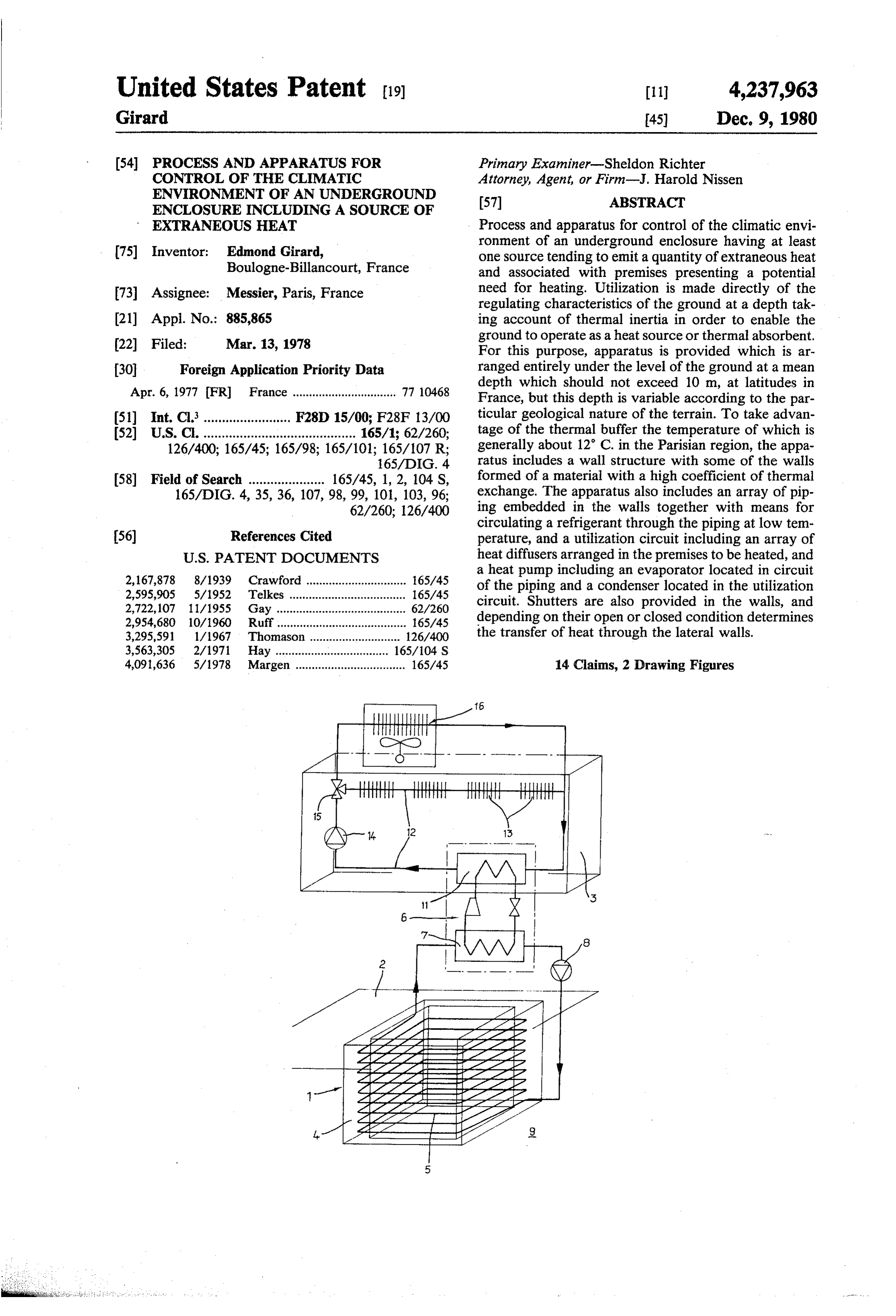
United States Patent (19) (11) 4,237,963 Girard 45) Dec. 9, 1980 (54) PROCESS AND APPARATUS FOR Primary Examiner-Sheldon Richter CONTROL OF THE CLMATIC Attorney, Agent, or Firm-J. Harold Nissen ENVIRONMENT OF AN UNDERGROUND (57) ABSTRACT
ENCLOSURE INCLUDING ASOURCE OF
EXTRANEOUS HEAT Process and apparatus for control of the climatic envi ronment of an underground enclosure having at least (75) Inventor: Edmond Girard, one source tending to emit a quantity of extraneous heat Boulogne-Billancourt, France and associated with premises presenting a potential 73 Assignee: Messier, Paris, France need for heating. Utilization is made directly of the regulating characteristics of the ground at a depth tak 21 Appl. No.: 885,865 ing account of thermal inertia in order to enable the (22 Filed: Mar. 13, 1978 ground to operate as a heat source or thermal absorbent. For this purpose, apparatus is provided which is ar 30 Foreign Application Priority Data ranged entirely under the level of the ground at a mean Apr. 6, 1977 (FR) France ................................ 77 10468 depth which should not exceed 10 m, at latitudes in France, but this depth is variable according to the par (51) Int. Cl......................... F28D 15/00; F28F 13/00 ticular geological nature of the terrain. To take advan 52 U.S. C. .......................................... 165/1; 62/260; tage of the thermal buffer the temperature of which is 126/400; 165/45; 165/98; 165/101; 165/107 R; generally about 12 C. in the Parisian region, the appa 165/DIG. 4 ratus includes a wall structure with some of the walls 58) Field of Search ..................... 165/45, 1, 2, 104 S, formed of a material with a high coefficient of thermal 165/DIG. 4, 35, 36, 107,98, 99, 101, 103, 96; exchange. The apparatus also includes an array of pip 62/260; 126/400 ing embedded in the walls together with means for circulating a refrigerant through the piping at low tem 56) References Cited perature, and a utilization circuit including an array of
2,167,878 8/1939 Crawford ............................... 165/45 a heat pump including an evaporator located in circuit 2,595,905 5/1952 Telkes ......... ... 165/45 of the piping and a condenser located in the utilization 2,722,107 11/1955 Gay ..... ... 62/260 circuit. Shutters are also provided in the walls, and 2,954,680 10/1960 Ruff ............. ... 165/45 depending on their open or closed condition determines 3,295,591 1/1967 Thomason ... 126/400 the transfer of heat through the lateral walls. 3,563,305 2/1971 Hay ...... ... 165/104 S 4,091,636 5/1978 Margen .................................. 165/45 14 Claims, 2 Drawing Figures
Page 2
Drawing sheet — no readable text.
Page 3
Drawing sheet — no readable text.
Page 4
To this end, the enclosure under consideration should
PROCESS AND APPARATUS FOR CONTROL OF be arranged entirely under the level of the ground, at a THE CLMATIC ENVIRONMENT OF AN mean depth which should not in general exceed 10 m, in UNDERGROUND ENCLOSURE INCLUDING A our latitudes, this depth being however variable accord SOURCE OF EXTRANEOUS HEAT 5 ing to the particular geological nature of the terrain in which the enclosure under consideration will be embed
This invention relates to a process and apparatus for ded, in order to take advantage of the effect of the control of the climatic environment of an underground thermal buffer furnished by the surrounding terrain, of enclosure, including at least one source tending to emit which the temperature over the year, at this depth, is a quantity of extraneous heat, and possibly associated 10 substantially constant, and is, for example, about 12 C. with premises presenting a potential need for heating. in the Parisian region.
By "a source tending to emit a quantity of extraneous The present invention provides a process for the heat' is to be understood any apparatus, machinery or control of the climatic environment of a subterranean groups of machines of which the use or the operation is enclosure including at least one source capable of emit inevitably accompanied by a dissipation of unwanted 15 ting a quantity of extraneous heat, which comprises thermal energy, both from the point of view of the promoting the transfer of heat through the walls of the environment and from the point of view of the appara enclosure from the ground to the enclosure due to the tus or the machine, heating of which could prejudice its natural phenomenon of thermal counterbalancing, in performance, which may render it essential to arrange 20 order to draw upon the thermal energy stored in the such sources of extraneous heat within enclosures or ground to maintain the said enclosure at the tempera rooms which are air conditioned, or of which the cli ture of the ground, and, in the event of the emission of matic environment is controlled. extraneous heat from the said source or sources, either As traditional examples may be quoted, computer promoting the transfer of heat through the walls of the rooms and telephone exchanges, where, respectively, enclosure from the latter to the ground due to the said the computers and the telephone bays when functioning 25 counterbalancing phenomenon, in order to draw upon usually dissipate a quantity of extraneous heat which is the capacity of the ground for storage of thermal energy so substantial that it is necessary to blow into the prem or and to maintain the enclosure at a temperature equal to ises containing these installations, cold air from refriger slightly above that of the ground, inhibiting the said ation units, the blowing being effected, for example, thermal transfer from the enclosure to the ground to through a false floor, and the air reheated by contact 30 satisfy an occasional need for heating, or controlling the with the sources of extraneous heat being evacuated to said thermal transfer in such a manner that part of the atmosphere through a false ceiling; while.in winter for storedthermal energy emitted from said source or sources is example, a heating installation can be brought into oper in the ground and part is retained to satisfy a ation to maintain these premises at an acceptable tem 35 lesser need for heating.
perature without involving any alteration in the opera outAnthis apparatus according to the invention, for carrying process, comprises a subterranean enclosure tion of the installations. This does not take account of the personnel involved in the operation of these installa extraneousorheat, including intended to include at least one source of the said enclosure comprising a wall tions, and who reside in the neighbouring premises or structure of which at least the lateral walls are formed annexes, such as offices, presenting a potential need of 40 a material with a high coefficient of thermal ex heating which is not unimportant since this need exists, of change, the internal surfaces of said lateral walls being in our latitudes, for about half of the year.
In order to promote the evacuation of the extraneous thermallybyinsulating covered an array of movable shutters formed of a material, and the arrangement heat to atmosphere, the installations previously exem being plified are disposed in premises at surface level, includ 45 fer of heat through said of such that opening the shutters promotes trans lateral walls whilst closure of ing, in addition, the necessary refrigeration and heating the shutters inhibits it.
installations, and adjacent to the offices heated by a In the case where this underground enclosure is asso possible second heating installation. ciated with premises frequented by personnel involved It is known, on the other hand, that the variations in in the functioning of the installations located in this the temperature of the external air, which are of two 50 types, diurnal variation and annual variation, of which enclosure and constituting the sources of extraneous heat, it is advantageous, in order to satisfy the potential the amplitude is variable in accordance with the cli need of heating of these premises, to transfer to them a mate, are repeated in the strata of the ground, with an part of the heat tending to become transferred from the attenuation which increases as the depth of the strata is ground to the enclosure, and thus to draw upon part of increased. Moreover, the minima and maxima of tem 55 the thermal energy stored in the ground to heat the perature at a given depth undergo, in relation to those premises. In addition, upon the emission into the enclo of the external temperature, delays of which the impor sure of a quantity of extraneous heat, the process ac tance likewise increases with the depth. In the Parisian cording to the invention consists in transferring into the region, it has been verified that the diurnal variation is practically negligible from a depth of 0.80 m., and the 60 premises this quantity of extraneous heat, if necessary reduced by a second quantity of heat transferred annual variation from a depth of 10 m. through the walls of the enclosure towards the ground, The idea at the basis of the invention consists in utilis if the quantity of extraneous heat emitted is greater than ing directly the regulating characteristics of the ground that required to heat the premises, whereby the capacity at depth, taking account of the thermal inertia which is of the ground for storing thermal energy is used to possessed thereby, in order to cause it to operate as a 65 absorb the excess of the extraneous heat. heat source or, inversely, as a thermal absorbent, ac According to one embodiment of the invention, the cording to the needs of the moment, in relation to an apparatus further comprises an array of piping embed enclosure including the sources of extraneous heat. ded in the walls of the enclosure, means for circulating
Page 5
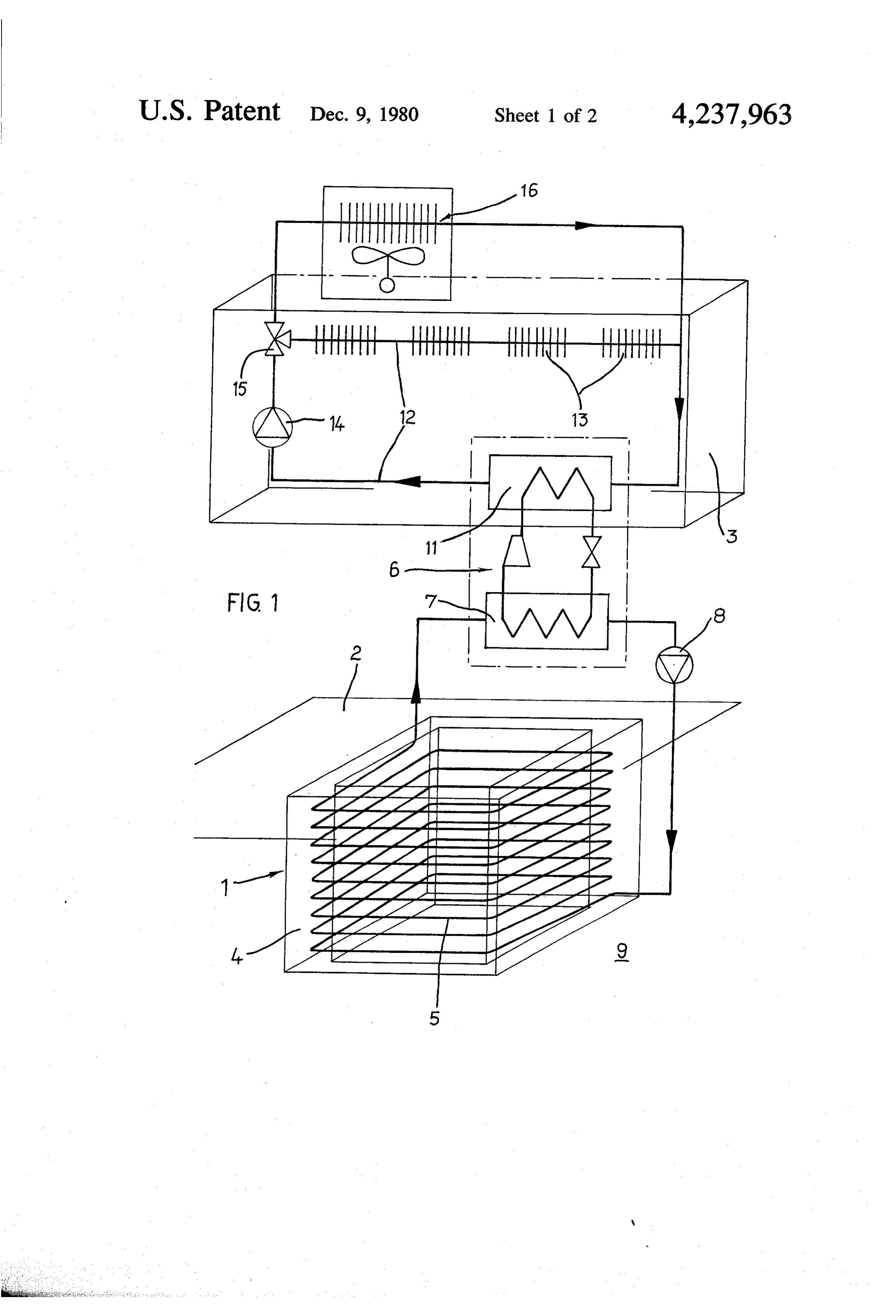
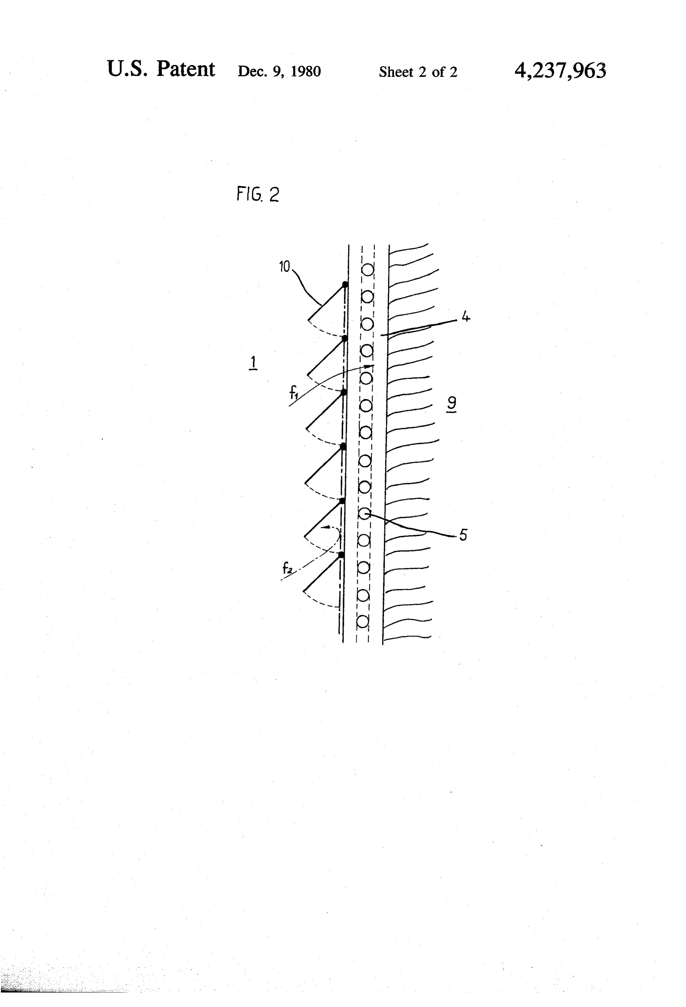
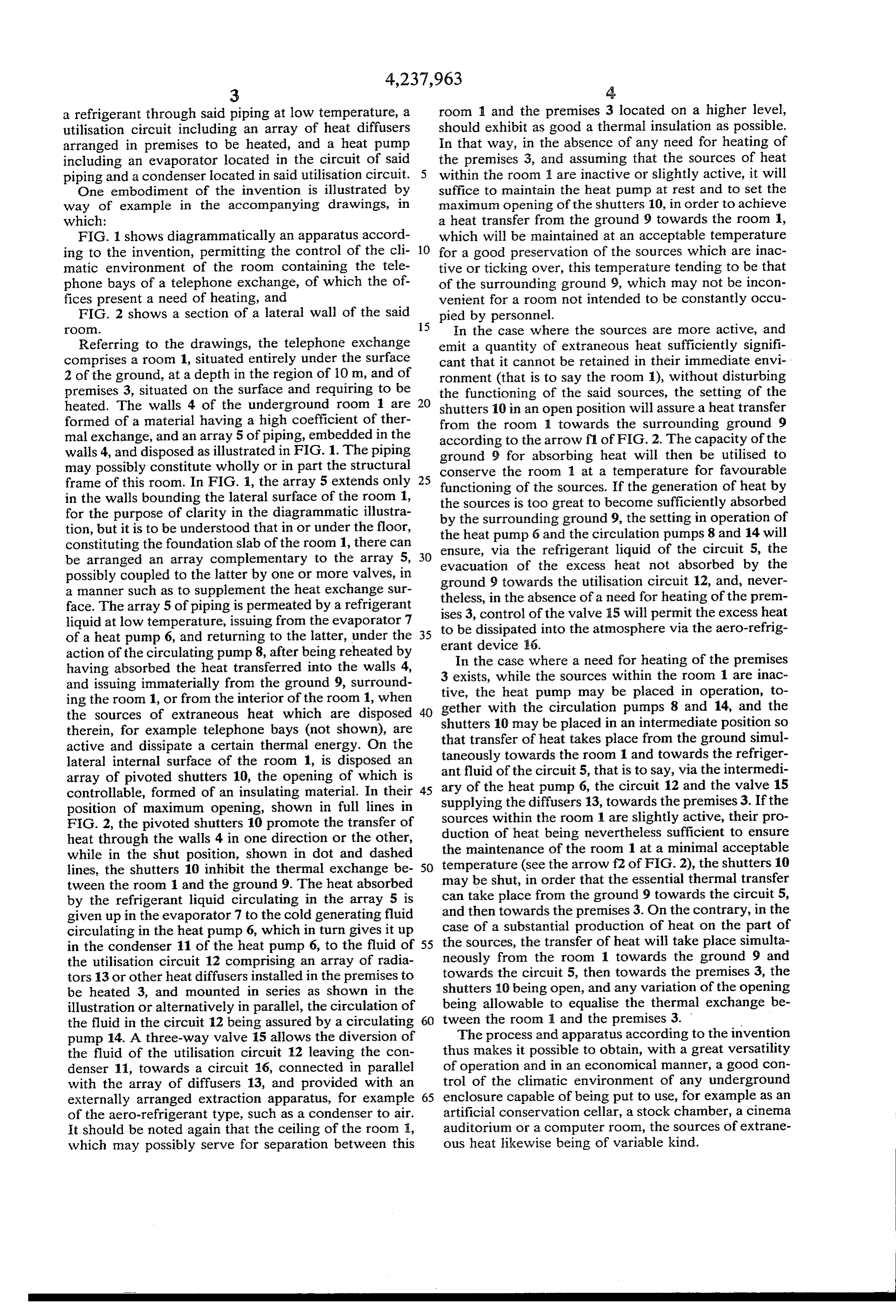
a refrigerant through said piping at low temperature, a room 1 and the premises 3 located on a higher level, utilisation circuit including an array of heat diffusers should exhibit as good a thermal insulation as possible. arranged in premises to be heated, and a heat pump In that way, in the absence of any need for heating of including an evaporator located in the circuit of said the premises 3, and assuming that the sources of heat piping and a condenser located in said utilisation circuit. 5 within the room are inactive or slightly active, it will One embodiment of the invention is illustrated by suffice to maintain the heat pump at rest and to set the way of example in the accompanying drawings, in maximum opening of the shutters 10, in order to achieve which: a heat transfer from the ground 9 towards the room 1, FIG. 1 shows diagrammatically an apparatus accord which will be maintained at an acceptable temperature ing to the invention, permitting the control of the cli 10 for a good preservation of the sources which are inac matic environment of the room containing the tele tive or ticking over, this temperature tending to be that phone bays of a telephone exchange, of which the of of the surrounding ground 9, which may not be incon fices present a need of heating, and venient for a room not intended to be constantly occu FIG. 2 shows a section of a lateral wall of the said pied by personnel.
OO. 15 In the case where the sources are more active, and Referring to the drawings, the telephone exchange emit a quantity of extraneous heat sufficiently signifi comprises a room 1, situated entirely under the surface cant that it cannot be retained in their immediate envi 2 of the ground, at a depth in the region of 10 m, and of ronment (that is to say the room ), without disturbing premises 3, situated on the surface and requiring to be the functioning of the said sources, the setting of the heated. The walls 4 of the underground room 1 are 20 shutters 10 in an open position will assure a heat transfer formed of a material having a high coefficient of ther from the room 1 towards the surrounding ground 9 mal exchange, and an array 5 of piping, embedded in the according to the arrow fl of FIG. 2. The capacity of the walls 4, and disposed as illustrated in FIG. 1. The piping ground 9 for absorbing heat will then be utilised to may possibly constitute wholly or in part the structural conserve the room 1 at a temperature for favourable frame of this room. In FIG. 1, the array 5 extends only 25 functioning of the sources. If the generation of heat by in the walls bounding the lateral surface of the room 1, the sources is too great to become sufficiently absorbed for the purpose of clarity in the diagrammatic illustra by the surrounding ground 9, the setting in operation of tion, but it is to be understood that in or under the floor, constituting the foundation slab of the room 1, there can the heat pump 6 and the circulation pumps 8 and 14 will ensure, via the refrigerant liquid of the circuit 5, the be arranged an array complementary to the array 5, 30 evacuation of the excess heat not absorbed by the possibly coupled to the latter by one or more valves, in ground 9 towards the utilisation circuit 12, and, never a manner such as to supplement the heat exchange sur theless, in the absence of a need for heating of the prem face. The array 5 of piping is permeated by a refrigerant ises 3, control of the valve 15 will permit the excess heat liquid at low temperature, issuing from the evaporator 7 of a heat pump 6, and returning to the latter, under the 35 to be dissipated into the atmosphere via the aero-refrig action of the circulating pump 8, after being reheated by erant device 16.
In the case where a need for heating of the premises having absorbed the heat transferred into the walls 4, 3 exists, and issuing immaterially from the ground 9, surround tive, thewhile the sources within the room 1 are inac heat pump may be placed in operation, to ing the room 1, or from the interior of the room 1, when gether with the circulation pumps 8 and 14, and the the sources of extraneous heat which are disposed 40 shutters 10 may be placed in an intermediate position so therein, for example telephone bays (not shown), are that transfer of heat takes place from the ground simul active and dissipate a certain thermal energy. On the taneously lateral internal surface of the room 1, is disposed an ant fluid oftowards the room 1 and towards the refriger the circuit 5, that is to say, via the intermedi array of pivoted shutters 10, the opening of which is ary of the heat pump 6, the circuit 12 and the valve 15 controllable, formed of an insulating material. In their 45 supplying the diffusers 13, towards the premises 3. If the position of maximum opening, shown in full lines in sources within the room 1 are slightly active, their pro FIG. 2, the pivoted shutters 10 promote the transfer of heat through the walls 4 in one direction or the other, duction of heat being nevertheless sufficient to ensure while in the shut position, shown in dot and dashed the maintenance of the room 1 at a minimal acceptable lines, the shutters 10 inhibit the thermal exchange be 50 temperature (see the arrow f2 of FIG. 2), the shutters 10 tween the room 1 and the ground 9. The heat absorbed may be shut, in order that the essential thermal transfer by the refrigerant liquid circulating in the array 5 is can take place from the ground 9 towards the circuit 5, given up in the evaporator 7 to the cold generating fluid and then towards the premises 3. On the contrary, in the circulating in the heat pump 6, which in turn gives it up case of a substantial production of heat on the part of in the condenser 11 of the heat pump 6, to the fluid of 55 the sources, the transfer of heat will take place simulta the utilisation circuit 12 comprising an array of radia neously from the room 1 towards the ground 9 and towards the circuit 5, then towards the premises 3, the tors 13 or other heat diffusers installed in the premises to shutters be heated 3, and mounted in series as shown in the 10 being open, and any variation of the opening illustration or alternatively in parallel, the circulation of being allowable to equalise the thermal exchange be the fluid in the circuit 12 being assured by a circulating 60 tween the room 1 and the premises 3. pump 14. A three-way valve 15 allows the diversion of The process and apparatus according to the invention the fluid of the utilisation circuit 12 leaving the con thus makes it possible to obtain, with a great versatility denser 11, towards a circuit 16, connected in parallel of operation and in an economical manner, a good con with the array of diffusers 13, and provided with an trol of the climatic environment of any underground externally arranged extraction apparatus, for example 65 enclosure capable of being put to use, for example as an of the aero-refrigerant type, such as a condenser to air. artificial conservation cellar, a stock chamber, a cinema It should be noted again that the ceiling of the room 1, auditorium or a computer room, the sources of extrane which may possibly serve for separation between this ous heat likewise being of variable kind.
Page 6
It should be understood that without departing from ture of the ground, said lateral walls having open the scope of the invention, it is possible to associate with ings in their internal surfaces; the described apparatus any means permitting, for ex an array of movable shutters adapted to cover said ample, the introduction into the underground room of openings in the internal surfaces of said lateral fresh air in a quantity determined as a function, for 5 walls, said array of movable shutters being formed example, of the temperature of the underground room of a thermally insulating material, the arrangement and/or the external air, as well as any means for ventila being such that movement of said shutters for tion or standby heating of the premises. opening thereof promotes transfer of heat through What we claim is: said openings in said lateral walls while movement 1. A process for the control of the climatic environ 10 of said shutters for closure of the shutters inhibits it; ment of a subterranean enclosure including at least one and, source capable of emitting a quantity of extraneous means to control said shutters, in the event of the heat, which comprises emission of extraneous heat from the said source or promoting the transfer of heat through selected parts sources, either to promote the transfer of heat of the walls of the enclosure from the ground to the 15 through said openings in the walls of the enclosure enclosure due to the natural phenomenon of ther from the latter to the ground due to the counterbal mal counterbalancing in order to draw upon the ancing phenomen, in order to draw upon the ca thermal energy stored in the ground to maintain pacity of the ground for storage of thermal energy the enclosure at the temperature of the ground, and and to maintain the enclosure at a temperature in the event of the emission of extraneous heat from 20 equal to or slightly above that of the ground, or to the source or sources, either controlling and pro inhibit the thermal transfer form the enclosure to moting the transfer of heat through the walls of the the ground to satisfy an occasional need for heat enclosure from the latter to the ground due to the ing, or to control the thermal transfer in such a counterbalancing phenomenon in order to draw manner that part of the thermal energy emitted upon the capacity of the ground for storage of 25 from said source or sources is stored in the ground thermal energy and to maintain the enclosure at a and part is retained to satisfy a lesser need for heat temperature equal to or slightly above that of the ing.
ground, 4. Apparatus as claimed in claim 3 in combination inhibiting said thermal transfer from the enclosure to with a premise presenting an occasional need for heat the ground to satisfy an occasional need for heating 30 ing comprising:
or controlling said thermal transfer in such a man premises presenting said occasional need for heating ner that part of the thermal energy emitted from associated with said subterranean enclosure; and, said source or sources is stored in the ground and said enclosure in addition to transferring to said part is retained to satisfy a lesser need for heating, premises a part or the whole of the thermal energy and 35 emitted by said sources, in order to satisfy said transferring the residual extraneous heat from the need, also transfers to said premises a part of the enclosure through the selected parts to the atmo heat transferred from the ground towards said sphere where the extraneous heat emitted by the enclosure, in order to satisfy the need when said sources is greater than the total of both that which sources are idle or do not emit sufficient thermal is capable of being absorbed by the ground and that energy to satisfy the need.
which is required to satisfy the need for heating. 5. Apparatus as claimed in claim 3 or 4 wherein said 2. A process as claimed in claim 1, wherein the said source comprises:
subterranean enclosure is associated with premises pres an array of piping embedded in the walls of the enclo enting the said occasional need for heating, and the said sure; and, process further comprises, in addition to transferring to 45 means to circulate a refrigerant through said piping at said premises a part or the whole of said thermal energy a low temperature.
emitted by said sources, in order to satisfy said need, the 6. Apparatus as claimed in claim 4, wherein said step of controlling and transferring to said premises a source comprises: . part or all of the heat transferred from the ground an array of piping embedded in the walls of said en towards said enclosure, in order to satisfy the said need 50 closure, and when the said sources are idle or do not emit sufficient means to circulate a refrigerant through said piping at thermal energy to satisfy said need. a low temperature; and, 3. An apparatus for the control of the climatic envi said premises comprising:
ronment of a subterranean enclosure having at least one a utilization circuit including an array of diffusers source tending to emit a quantity of heat, including in 55 arranged in said premises to be heated, associated combination: with said array of piping for the transfer of heat a subterranean enclosure comprising at least one between said array of piping and said array of dif source capable of including or intended to include fusers.
a quantity of extraneous heat; 7. Apparatus as claimed in claim 6, comprising: said enclosure comprising a wall structure of which 60 a heat pump including an evaporator located in the at least the lateral walls are formed of a material circuit of said piping; and, with a high coefficient of thermal exchange, said a condenser located in said utilization circuit. wall material being effective to promote the trans 8. Apparatus according to claim 6 or 7, including a fer of heat through the walls of said enclosure from circuit incorporating an extractor for dissipating heat to the ground to the enclosure due to the natural 65 atmosphere connected in parallel with the heat diffusers phenomenon of thermal counterbalancing, in order of said utilization circuit.
to draw upon the thermal energy stored in the 9. Apparatus as claimed in claim 8, further compris ground to maintain said enclosure at the tempera ing a supplementary array of pipes arranged under the
Page 7
floor of said enclosure and connected to the first array a utilization circuit associated with said source and by valve means in such a manner to augment the capac premises to be heated, said utilization circuit com ity for heat exchange with the ground. prising an array of diffusers arranged in said prem 10. Apparatus as claimed in claim 4, wherein said ises to be heated.
source comprises: 12. Apparatus as claimed in claim 11, including an array of piping embedded in the walls of said en a circuit incorporating an extractor for dissipating closure; heat to the atmosphere connected in parallel with means to circulate a refrigerant through said piping at the heat diffusers of said utilization circuit. a low temperature; and, 13. Apparatus as claimed in claim 12, comprising said shutters being on the inside of said enclosure and 10 a supplementary array of pipes arranged under the when opened aid in the t1ansfer of residual extrane floor of said enclosure and valve means connecting ous heat from said enclosure to said atmosphere said first-mentioned array to said supplementary when the extraneous heat emitted by said sources is array of pipes in such a manner to augment the capacity for heat exchange with the ground.
greater than the total of both that which is capable 15 14. Apparatus as claimed in claim 3, wherein of being absorbed by the ground and that which is said shutters are pivotally connected to the lateral required to satisfy the need for heating. walls on the inside of said enclosure. 11. Apparatus as claimed in claim 10, including : : le
Provenance
- Collection
- Cited prior art
- Original PDF
- patentimages.storage.googleapis.com →
- Filed
- 1978-03-13
- Pages
- 7
- Method
- pdftotext (the PDF's own text layer) + pdftoppm 300dpi page scans
- Source
- Google Patents bibliographic record
- Granted
- 1980-12-09
- Inventors
- Edmond Girard; Messier SA
- Transcribed from
- patentimages.storage.googleapis.com →