patent · US4479487
Apparatus for solar water heating
30 October 1984
Page 1 — bibliographic record
United States Patent (19) 11 Patent Number: 4,479,487 Migdal (45) Date of Patent: Oct. 30, 1984 54 APPARATUS FORSOLAR WATER HEATING Primary Examiner-James C. Yeung Attorney, Agent, or Firm-Julian Caplan 76 Inventor: Ilya Migdal, 3366 Verloi Ter, Palo
Alto, Calif. 94303 57 ABSTRACT 21 Appl. No.: 501,114 A solar water heating system comprises a solar collec tor having coils consisting of several stages, some of the (22 Filed: Jun. 6, 1983 coils having transparent covers having different heat (30) Foreign Application Priority Data insulation effects increasing with the temperature in the coil stages. Water is introduced to the collector either
Jun. 9, 1982 (IL) Israel ........................................ 66014 from a cold water source or from the hot water storage tank. The hot water discharge from the collector is 51) int. Cl. ................................................. F24, 3/02 divided into two branches, one branch leading to a 52 U.S. C. .................................... 126/422; 126/437; mixing valve and one to a storage tank. Discharge from 126/419 the storage tank leads either to the hot water line to the 58) Field of Search ............... 126/422, 423, 432, 435, consumer or to an excess water utilization means, such 126/436, 437, 417, 445, 446; 165/18 as a spray to wash the collector, to an irrigation system, 56) References Cited a roof cooling system or the like. The present invention improves the efficiency of the system and increases the
4,019,495 4/1977 Frazier et al. ....................... 126/437 may be used to reduce cost.
4,191,166 3/1980 Saarem et al. .. 126/422 4,270,522 6/1981 Vandenberg ........................ 126/437 13 Claims, 9 Drawing Figures
Page 2
Drawing sheet — no readable text.
Page 3
Drawing sheet — no readable text.
Page 4
Drawing sheet — no readable text.
Page 5
Drawing sheet — no readable text.
Page 6
Drawing sheet — no readable text.
Page 7
Drawing sheet — no readable text.
Page 8
Another object is to provide a construction of a solar
APPARATUS FOR SOLAR WATER HEATING collector which is simple to manufacture and conve nient to transport and assemble.
FIELD OF INVENTION Other objects of the present invention will become The present invention relates to conversion of solar apparent upon reading the following specification and energy into usable energy and more particularly to an referring to the accompanying drawings in which simi apparatus for solar water heating. lar characters of reference represent corresponding parts in each of the several views.
DESCRIPTION OF PRIOR ART IN THE DRAWINGS
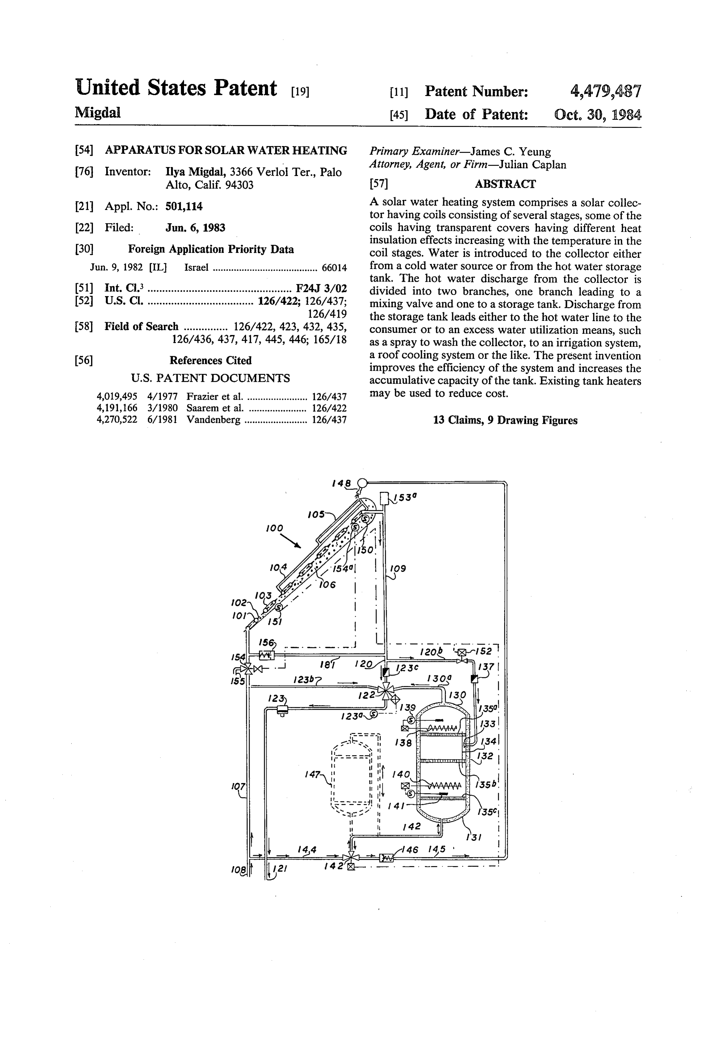
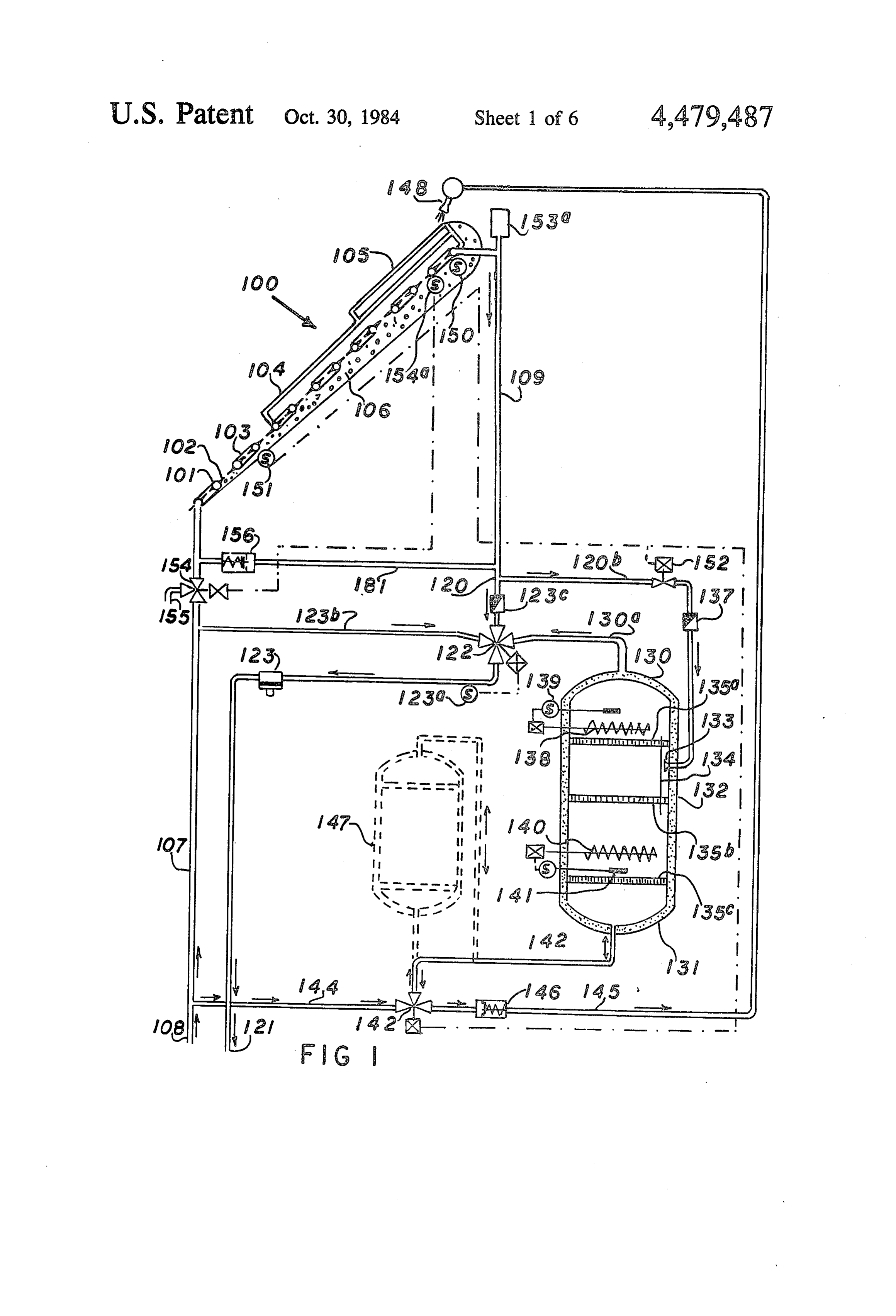
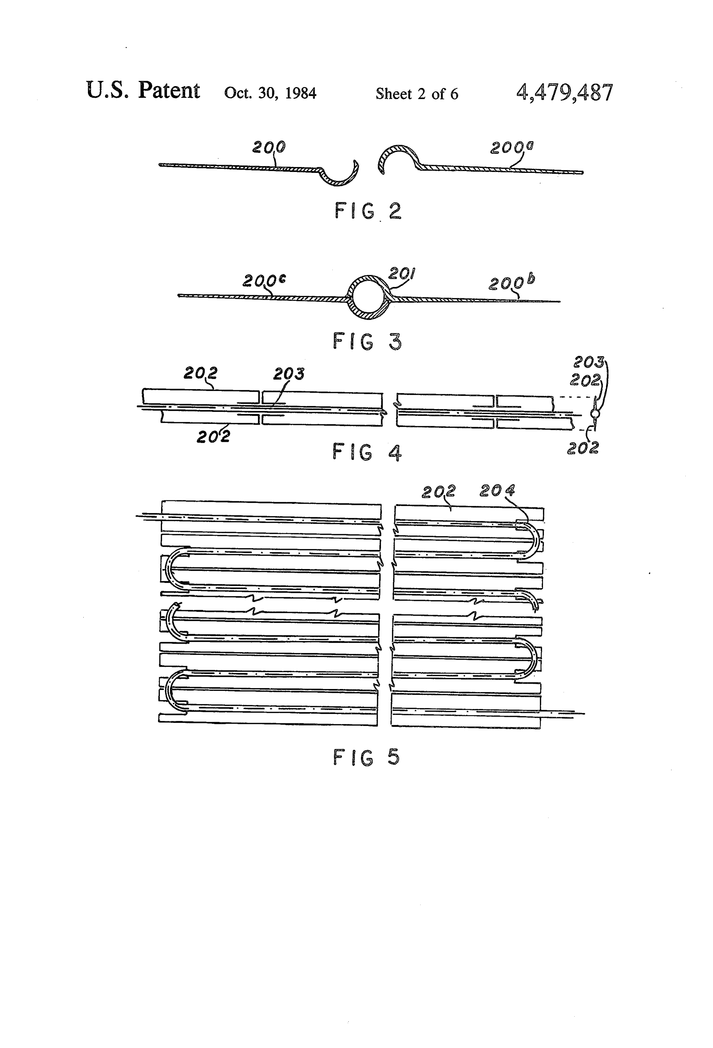
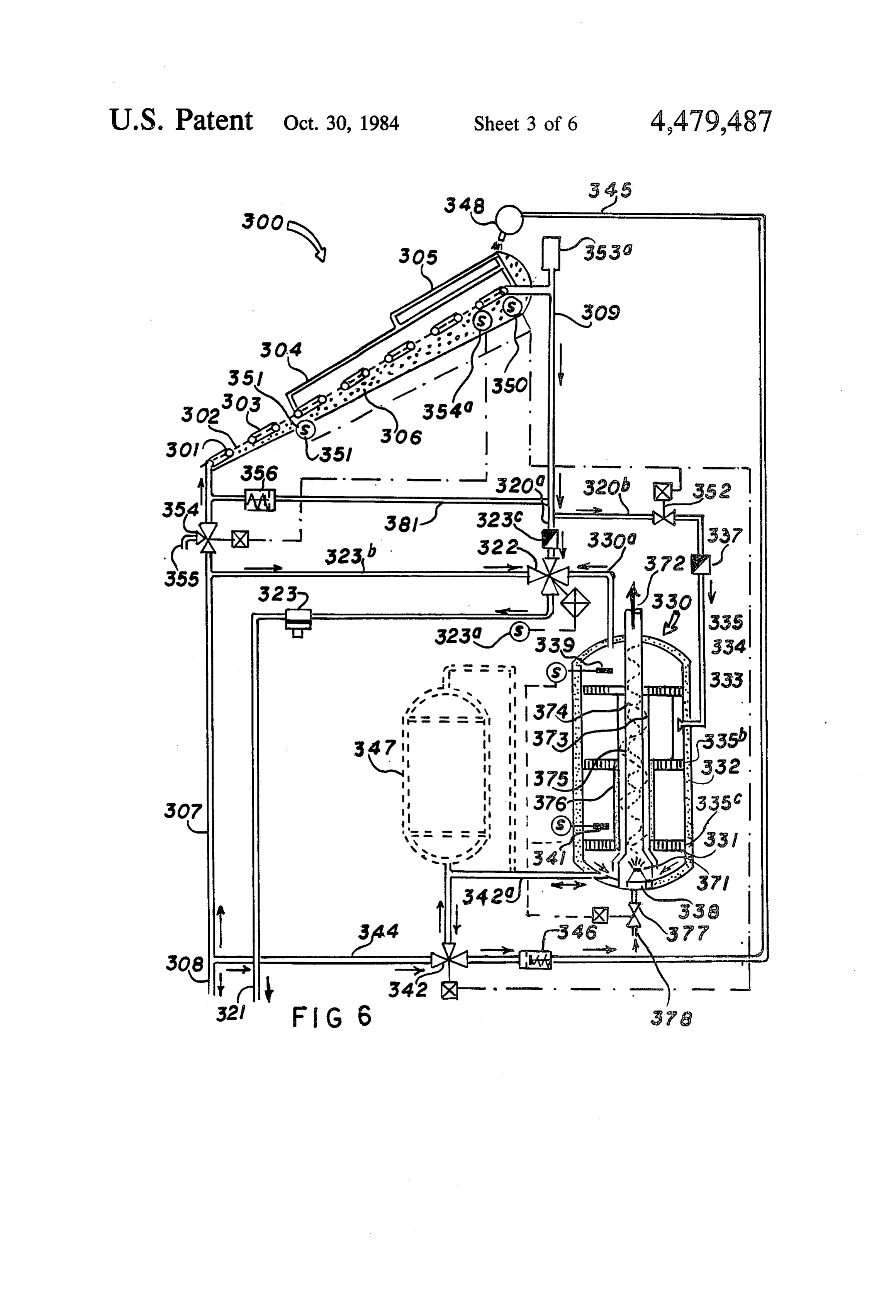
The desirability of utilizing solar energy for domestic water heating has long been recognized. Conventional of FIG. hot 1 is a solar water heating system with selection water for accumulation using the head in the apparatus for solar water heating can be divided into water supply line, and with an electric reserve heater; two groups: (1) working on the principle of natural FIG. 2 is a cross-sectional view of rolled sections circulation of water due to differences in specific gravi 15 used for a solar collector unit prior to assembly; ties of hot and cold water (so-called thermosyphon); FIG. 3 is a cross-sectional view of the structure of and (2) working on the principle of positive circulation, FIG. 2 with the parts assembled; i.e., from a pump. FIG. 4 is a plan view of a strip shown in FIG. 3; Apparatus working on the thermosyphon principle FIG. 5 is an elevational view of an assembled solar comprises a storage tank located above a solar heat 20 collector unit formed from the strip of FIG. 4; collector, which consists of a heat-absorbing surface in FIG. 6 is a view similar to FIG. 1 modified for use of a heat conductive relation with water circulating in a a gas reserve heater;
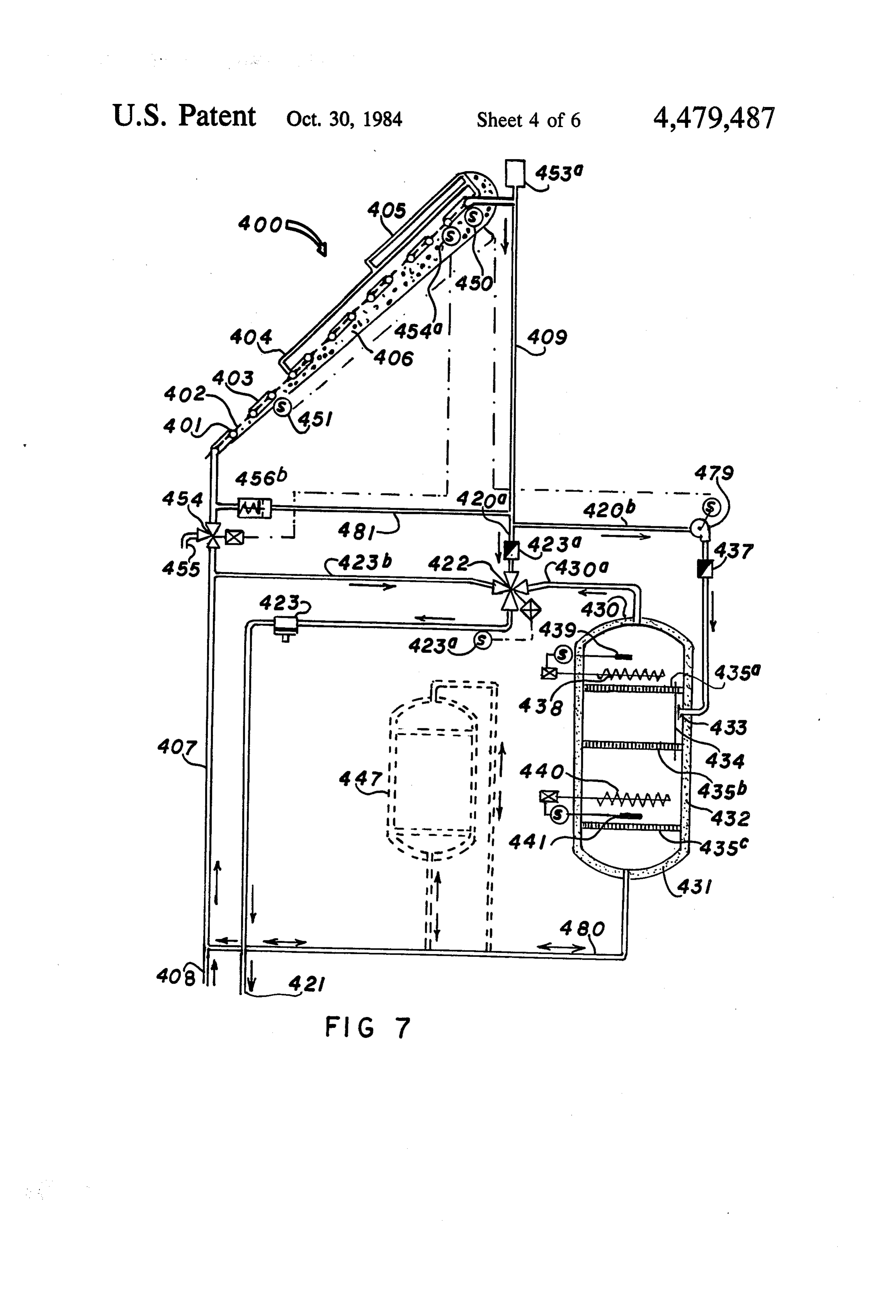
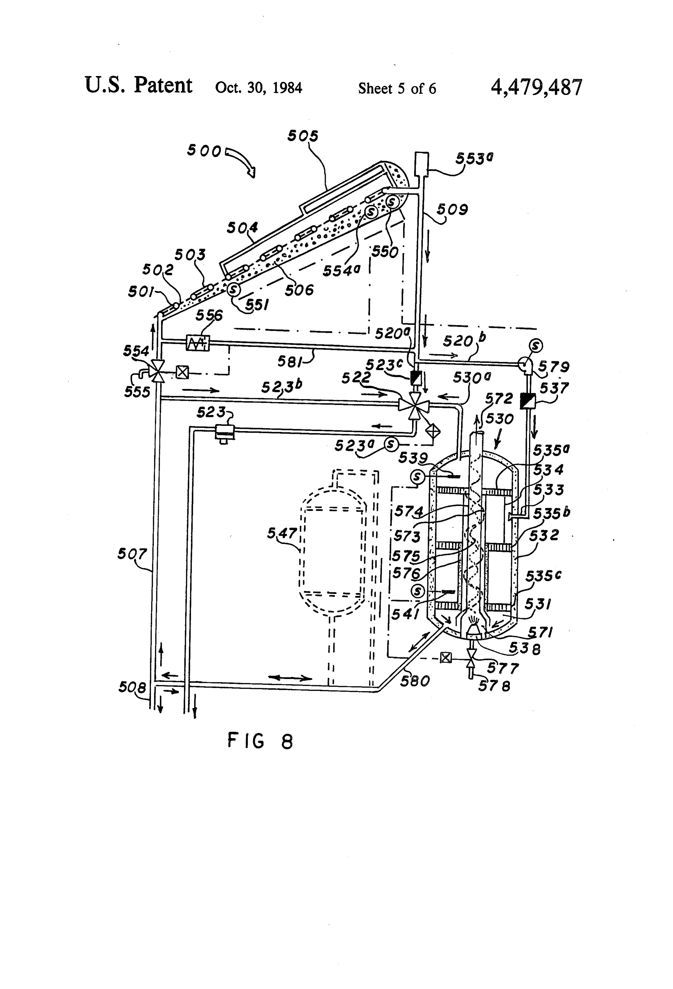
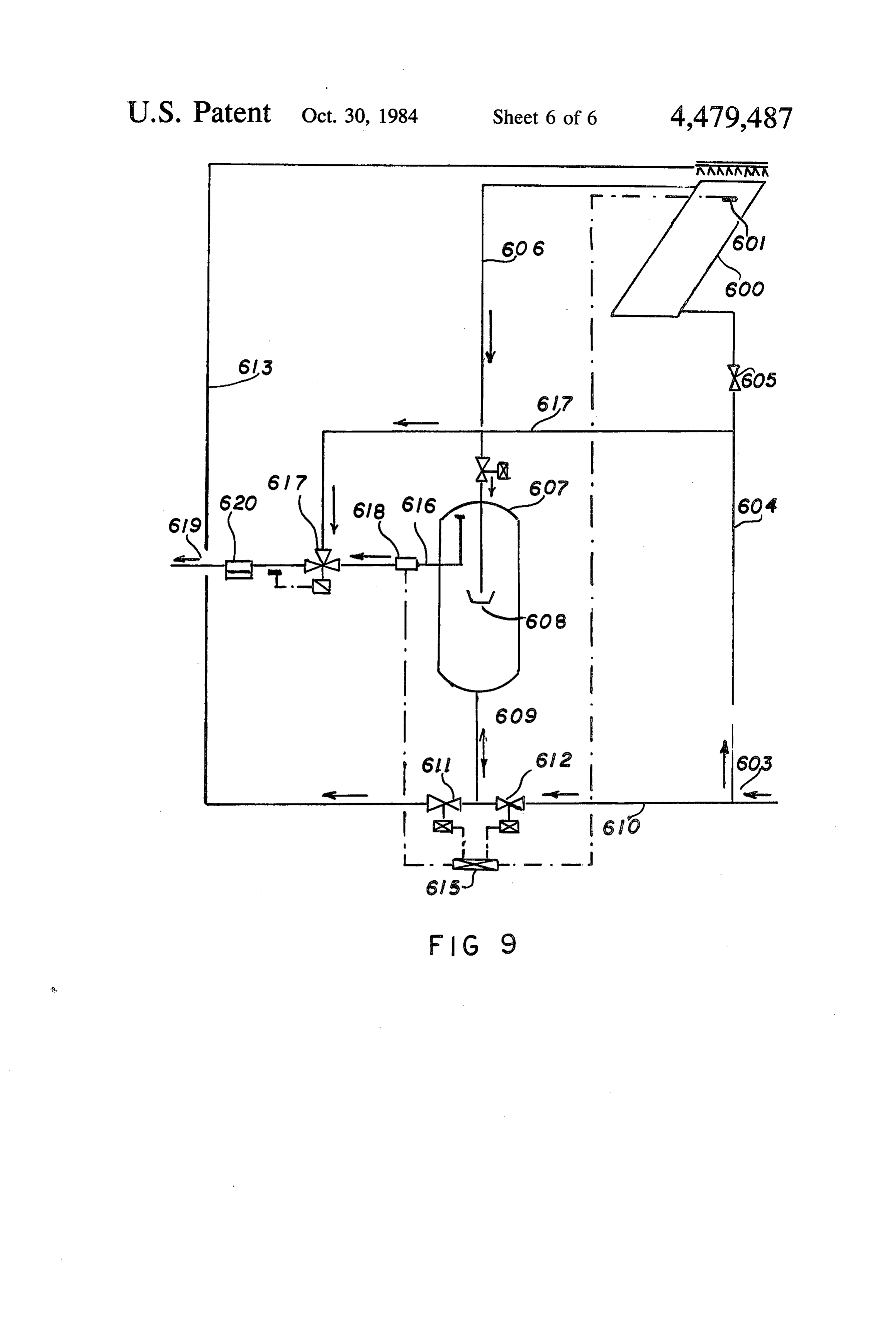
closed system. Water is circulated in said system due to FIG. 7 is a view similar to FIG. 1 of a solar water differences in specific gravities of hot and cold water. heating system using a small variable-capacity pump Hot water is discharged for use by the consumer from 25 and with an electric reserve heater; the upper part of the storage tank. The consumption of FIG. 8 is a view similar to FIG, 7 using a gas reserve hot water from the storage tank is compensated by heater; and additional supply of cold water to the lower part of the FIG. 9 is a view similar to FIG. 1 of a still further tank. From the collector water is fed into the intermedi modified embodiment.
ate part of the tank and discharged to the consumer 30 DESCRIPTION OF THE EMBODIMENT OF FIG. from the upper part of the tank. 1. Gravity-circulating thermosyphon systems require
Referring first to FIG. 1, a solar water heating system that the hot water storage tank be located above the comprises solar heat collector, which is often an architectural a multistage solar collector 100 composed of a coil 101 and a heat absorbing surface 102 in heat con disadvantage, especially in houses which are already 35 ductive relation with said coil 101. The coil 101 is di constructed. Therefore, pumped systems, which are vided into several parts, e.g., three stages connected in adaptable to any tank collector location, are preferable a series, which have transparent covers of different for retrofit applications.
A typical solar water-heating pump system consists 40 kinds. Three stages are shown in FIG. 1, i.e., first stage 103, second stage 104 and third stage 105. The first stage of the same elements as a thermosyphon system (storage 103 tank, solar heat collector and circulation system) plus a ment,may have no covering, as in the illustrated embodi pump used as a drive source for circulation. The storage second stagemay or it be covered with one layer of glass. The tank, therefore, can be located in any convenient place. the third stage 105is covered
Disadvantages of the conventional systems of both 45 This subdivision is determined with is covered two layers of glass.
types lie in their thermodynamical imperfection due to ing capacities at different stages because theheat by different absorb loss of heat the use of hot-water recirculation and a cyclically vari at each stage depends on the temperature differential able temperature in both the solar collector panel and between the absorbing surface and temperature of the the storage tank. Such systems lead to appreciable irre ambient atmosphere. Instead of glass, other solar heat versible energy losses and reduce hot-water storage by 50 transmitting materials--e.g., plastics-may be used. 30%. Therefore, the storage tank volume is assumed to Upon an increase of this temperature difference from equal daily hot water consumption by the consumer. one stage to another, it is expedient to reduce heat losses OBJECTS from the absorbing surface into the atmosphere, due to an increase in number of air layers formed between
Accordingly, it is an object of the present invention 55 layers of glass. The number of stages, as well as types of to provide an efficient apparatus for solar energy heat coatings on the absorbing surface and the number of ing. Another object is to increase efficiency for solar transparent layers will be determined in each particular energy utilization, and reduce weight, manufacturing case according to economic considerations and working and installation expenses. conditions.
Still another object of the invention is simplification 60 The same effect is improved by use of thermal insula of a solution to the probelm of the collector freezing. tion 106 of variable thickness on the back side of the It is a further object to provide such a system, which solar collector panel 100 with increase of the insulation can be used in conjunction with commonly used domes thickness from the cold end to the hot end. tic hot water systems, with only minor modifications. Pipe 107, supplying water from a water supply sys Another object is to reduce the volume of a storage 65 tem 108, is connected to the inlet side of the coil 101 of tank without the loss of its capacity. the solar collector 100. Because this pipe always Still another object of the invention is to reduce start supplies only cold water, it need not be insulated and ing time after interruption of operation. may be made of plastic material. An output side of the
Page 9
Best Available Copy
coil 0E is connected to a pipe 09. Because pipe 109 The utilization of the discharged water for washing serves to transport hot water, it should be made of a the Solar collector panels will make them maintenance metal such as copper and proferably provided with free and eliminate the necessity of manual cleaning insulation. The pipe 07, coil 101 and pipe 109 may have operations.
a relatively small diameter, e.g., of from ' to '', be- 5 The description given above concerns the main func cause they transport water at a small flow rate. tional units of the system. The following explanation The pipe 109 is branched into branch pipes 1.20a and relates to the automatic control means of the system. 20b. The branch 120a leads to a discharge point Two sensors 150 and 51 are located at the surface of through a four-way mixing control valve 122 and a the coil 101 at different levels, the sensor 150 being safety valve, e.g., a fusable insert 123. A temperature- 10 located at the outermost turn of the coil, and the sensor "esponsive sensor 123a is located beyond the mixing 151 is located below. A control valve 152 is located in valve 22 in branch 20a. Sensor 123a controls opera branch 20b. Valve 152 is actuated under the effect of a tion of four-way mixing valve 22 and maintains the predetermined temperature difference between temper temperature of water available to the consumer at a ature detected by the sensors 150 and 151. Opening of ieved not less than, e.g., 50° C. A check valve 123c is 15 valve 152 is adjusted, under control of the temperature located in the pipe i2Ga leading from the collector 100 difference, between complete opening and complete to the four-way mixing valve 122. closing. The control valve 152 is interlocked with valve E42 so that the latter is actuated simultaneously with
One of the important elements of the system is an operation inproved storage tank 130. The upper part of the stor of valve 152.
As has been mentioned above, this system makes it age tank is connected to the mixing valve 122 through a 20 possible pipe 230a. Casing 31 of tank 130 is covered with insula conventional to utilize pipes of smaller diameter than in a tion E32. The function of the storage tank is to accumu when it is necessary system. It may create complications, late, store and supply hot water. It is also used as a e.g., as a freeze protection to drain water from the system, reserve heater. The branch 20b from the solar collec means. A special air damper 25 153a is provided for this purpose. It comprises a small for 508 is connected to the tank 130 at point 33, extend volume closed container (of from 3 to 6 liters, i.e. about ing through casing 31 and directing the stream onto 1.5-2 volumes of that of the interior of the coil 01), gieilector wall 34, which, due to the effect of the so caiied "adherence' of the stream to the surface, ensures which101. A is connected to the uppermost point of the coil freeze protection valve 154 is provided in the upward or downward direction of the stream depend 30 ing on the tenaperature of water. In order to ensure pipe 107.
uniformity of distribution of flow of water, the tank 130 theAfreezing sensor 54a, which detects temperatures close to point, is attached to the surface of the coil is provided with flow levelling grids 35a, 135b and 01. The sensor 50 may fulfill the same function as the 35c. sensor i54a and control operation of the freeze protec A check valve 137 is located in branch 20b. An 35 tion valve 54.
clectric heater having a sensitive element 39 is located The pipe 109 is connected to pipe E8 and is provided in the upper part of the tank 130 above grid 35a, and an with a back-pressure check valve 156. A drain 55, eiectric heater 40 having a sensitive element 4 is controlled by valve 54, drains collector 100 and pipes located in the lower part of the tank 130 above grid 9 and E8.
35C. 40 FIG. 2 illustrates a preferred construction of coil 01. A pipe 342a discharges from the bottom of the tank A section used in such coil comprises a shaped element E30 and leads to one port of a three-way valve 142. 200 formed, e.g., by rolling from sheet metal of variable Another port valve 142 is connected to pipe 144 which thickness. In case of mass production, it may be shaped sextends to inlet pipe 107. The third port of valve 142 simultaneously with rolling on a rolling mill. Each sec leads to relief line 145. A back-pressure check valve 146 45 tion preferably tapers outwardly and has a semicircular is located in the line 45 beyond valve 42. hook-shaped inner end. As shown in FIG. 3, two such in the case of a reconstruction of an existing water sections 200a and 200b are combined by welding to eating installation equipped with an electric heater, the form a tube 20. Joints between two elements are i2ink F38, according to the present invention, is also used formed by welding or by any other method which pro simultaneously as an accumulator. If the capacity of 50 vides a seal against leakage.
tank 33 as an accumulator is insufficient, an additional The assembled unit may be of a considerable length receiver 47 may be installed between the output from and have a strip-like configuration shown in FIG. 4 the tank 33 and valve i42 and used as a reserve con with heat-transferring fins 202 and a water-transporting tainer. tube 203. Prior to bending the strips of FIG. 4 into coils, The reiief line 45 may be used for many purposes. 55 transverse slits and longitudinal inward extending his it may terminate in a spraying device A48, which notches are formed. Short tube sections 203 bridge the is used, e.g., for washing the outer surfaces of the trans space between slits and notches.
parent covers at the solar collector stages 104 and 105. FIG. 5 shows a completed solar panel. The structures Thus, water does not return to the system, but rather between slits and notches are reversely bent at the trans 3 removed therefron for further utilization. For exam- 60 verse slits. The bridging short tube sections 203 are bent 23, it aay be used for washing the panels of the solar into semicircular members 204 which interconnect the (coiiector, for cooling the roof of a building, for irriga oppositely directed parallel sections between slits. As tion purposes, etc. Water is removed in very small quan shown in FIG. 5, the semicircular sections partially tities, no more than one volume of the tank 130 per day. overlap the ends of the parallel sections. Therefore, the losses of water will cost little, whereas 65 The number of sections, their lengths and the manner ise advantages obtained due to utilization of this water, in which they are joined together are subject to consid especially in air polluted areas is much more apprecia erable variation. The form shown in FIGS. 2-5 is a e. presently preferred embodiment. The formation of the
Page 10
water-transporting coil and heat-absorbing surfaces the sensors 150 and 151, this action varies the tempera from an integral sheet-metal blank considerably in ture of water supplied to the storage tank 130. creases the heat-transferring efficiency in conducting During wintertime with reduced solar radiation, the the heat from the heat-absorbing surfaces to water. temperature of water from the collector 100 to the tank Operation of the system of FIG. 1 130 is reduced, e.g., to 75° C., depending on the temper ature of water in the water supply system 108. Thus, the
The apparatus for solar water heating described provision of the sensors 150 and 151 makes it possible to above and shown in FIG. 1 operates in the following automatically establish a reduced upper limit of the lane: water temperature for wintertime, whereby the tank is Cold water from the water supply system 108 is fed 10 filled entirely with water, e.g., at 75° C. instead of par via the pipe 107 to the cold side, i.e., to the inlet of the tially filling it with water at 85°C. This improves the coil 101 and subsequently through the first, second and efficiency of the system during wintertime. third stages 103, 104 and 105, respectively, of the solar The flow of water from the pipe 120b is directed to collector 100. On its way, the water is heated due to the deflector wall 134 and adheres thereto, as has been transfer of heat from the heat absorbing surface 102. 15 mentioned above. If this water is warmer than that in The heat-absorbing surface 102, in turn, is heated di the upper part of the tank 130, it flows upward. If it is rectly by sunlight at the first stage 103 and through the colder than water in the upper part of the tank it is transparent covers at the second stage 104 and third directed downward. In other words, the supplied water stage 105. The temperature of the water is gradually is automatically separated depending on its tempera increased from the first to the last stage, reaching the 20 ture. Thus, the whole interior of the tank is filled with limit 75-85' C. at the ultimate stage depending on hot water, even with possibly different temperatures at seasonal conditions. the upper end lower temperature at the bottom, and From the outermost turn of the solar collector 100, solar collector 100 operates in the manner most efficient water flows via the pipe 109 to branches 120a and 120b. 25 for the given weather conditions. This arrangement also Considering first the case when water from the solar reduces irreversible thermodynamic losses connected collector 100 is supplied directly to the consumer, by with the process of mixing between more heated and passing the storage tank 130, water flows through the less heated water.
The two-position valve 142 is switched simulta pipe 120a to the mixing valve 122, which at this moment neously is open, and is supplied further to the consumer through with actuation of the control valve 152, so that it covers the flow of cold water from the water supply pipe 121. When the system operates under these condi 30 line tions, the temperature of the water, flowing from the part 108 and opens the passage for water from the lower of the tank to the relief line 145 through the back solar collector to the mixing valve 122, will vary de up check valve 146. Water displaced from the relief line pending on the volume of the water supplied to the 145 is removed valve 122. The more the consumption, the lower the 35 utilized in variousviaother spraying devices 148 and may be ways, as above described.
temperature of the water. This can be considered as a Water in the tank 130 passes through the levelling positive factor because the efficiency of the collector is grids 135a, 135b and 135c. These increased in proportion to the decrease in temperature water of different temperatures grids and restrict mixing of ensure uniformity of the water taken from the collector, i.e., in this case of its motion.
the operation is shifted to the more efficient range. 40 In case there is no solar radiation, the solar collector When the temperature of the water supplied to the 100 does not supply hot water in required quantities and valve 122 is reduced below 50° C., under the control of the required quantity of hot water is taken from the the sensor 123a the mixer valve 122 will add a flow of storage tank 130. During this process hot water is sub hot water from the upper part of the storage tank 130 stituted for cold water, which is fed into the lower part through pipe 130a, under the pressure of cold water 45 of the tank 130 supplied during this period from the water supply line the temperaturefrom the water supply system 108. When 108 via the now open two-position three-way valve 142 130 is reduced below 50° inC.,the of water upper part of the tank the sensitive element 139 and pipe 42d, switches on the electric heater 138, maintaining the When the temperature of water beyond valve 122 is temperature of water in the upper part of the tank at a above 50 C., under the control of the sensor 123a, the 50 given level of 50° C. Thus, the consumer receives hot mixing valve 122 will add a flow of cold water taken water at 50° C. irrespective of weather conditions. through the pipe 123b from the cold water pipe 107. After sunset the sensitive element 141, which is If the valve 122 fails to keep the temperature above equipped with a time relay (not shown) checks the 50° C., a fusable insert 123 opens and water is drained temperature of water in the entire volume of the tank from the pipe 121. This prevents the danger of scalding, 55 130, and switches on the second heater 40, which starts which is an important factor in childcare facilities and heating water in the lower part of the tank 130 until the hospitals. entire volume of water in the tank is heated to the given Considering now operation of the system when water temperature.
is not supplied to the consumer or supplied in quantities Thus, both heaters 138 and 140 compensate for lack less than that supplied to the storage tank at 80 C., an 60 of solar radiation in the preceeding day and create a excess of hot water at a temperature of 80 C. is fed reserve volume required for average consumption of through the branch pipe 120b and the control valve 152 hot water in each particular installation. The second to the storage tank 130. This provides differential selec heater 140 operates either for a predetermined time or is tion of water for accumulation. switched off after the water has reached a predeter The operation of the control valve 152 is controlled 65 mined temperature at the location of the sensor 141. by the sensors 150 and 151, which detect the tempera In geographical areas where temperature can be re ture difference at the inlet and outlet of the collector duced below the freezing point, freeze protection means 100. By preserving the temperature difference between are required. Therefore, when the temperature is close
Page 11
to the freezing point, the sensor 150, or a specially pro with the pipe 409 which is provided with branch 420b. vided sensor 154a, actuates the freeze protection valve The latter is connected to a small variable-capacity 154, which stops the supply of cold water to the collec pump 479, e.g., of 20-40 watt power with head up to tor and at the same time drains water from the collector 0.5-2 kg/cm2. The pump 479 is controlled by the sen coil. At this moment the air, which has been trapped sors 450, 451 in the same manner as the valve 152 in the and compressed in the air damper 153a during the filling embodiment of FIG. 1. The lower part of the storage of the system, forces water out of the coil 101 under tank 430 is connected to a pipe 480, which is connected pressure. to the pipe 407. A pipe 481 connects the point of inter At the end of the process of draining the coil 101, the section between the supply line 408 and pipe 476 with back-pressure check valve 156 is actuated and water 10 the lowermost turn of the coil 401. contained in the pipe 109 is drained through the same The embodiment of FIG. 7 does not require applica freeze protection valve 154. tion of the control valve 152, two-position three-way In case of reconstruction of an existing local water valve 142, check valve 146 and pipe 145 used in FIG. 1. heating installation, the capacity of which is insufficient Furthermore, this version does not require secondary as an accumulator, water is fed from the bottom of the 15 utilization of the water displaced from the system. Thus, heater to the additional receiver 147 which, in this case, the system of FIG. 7 is closed. fulfills the same function as the main storage tank 130 in Operation of the System of FIG. 7 a newly designed construction.
DESCRIPTION OF EMBODIMENT OF FIG. 6 20 following manner:
The solar heating system of FIG. 7 operates in the
FIG. 6 illustrates a solar water heating system with Considering, first, the case when water is supplied to selection of hot water for accumulation using the head the consumer, the water supply line 408 supplies water in the water supply line, but in combination with a gas to the pipe 481 and flows to the lowermost point of the reserve heater. solar collector 400. As in the version of FIG. 1, water In principle, apparatus of this embodiment is similar 25 passes through the stages 413, 414, 415 of the collector to that of FIG. 1 with the distinction that a gas heater is 400 and from the upper end of the collector 400, it flows used instead of an electric one. However, it requires a into the pipe 409 and further to the four-way valve 422. modification of storage tank 330. The valve 422 directs water to the consumer line 421. A gas burner 338 is located in a combustion chamber When the temperature of the upper part of the collector 371, arranged in the lower part of the storage tank 330. 30 400 exceeds a predetermined level, e.g., of 85 C., the A gas flue 372 extends from the combustion chamber sensor 450 actuates the pump 479, which starts pumping 371 upwardly. The interior of the combustion chamber water to the storage tank 430. The sensor 450 is of a chamber 371 and the gas flue 372 are sealed against the proportional-type, and it adjusts the flow of the pump water-containing cavity of the tank 330. 479 depending on the water temperature. A water guiding shell surrounds the gas flue 372 in 35 The sequence in the tank is the same as described order to ensure an intensive heat transfer from the wall with regard to FIG. 1. From the bottom of the storage of the gas flue 372. A helical groove 375 is formed on tank 430, cold water is fed to the pipe 480, flows the inner surface of the gas flue 372 in order to intensify through the pipe 407 and further to the lower end of the the heat-exchange process and a helical groove 374 is coil 401. However, this cycle does not comprise recir provided on the outer surface of the gas flue for the 40 culation in terms of conventional closed-type solar same purpose. The water guiding shell 373 is provided water heating systems, because in this case the solar with thermal insulation 376 for accumulation of hot collector 400 receives cold water from the lower part of water in the upper part of the tank 330, the tank 430. Nevertheless, physically circulation is Sensitive elements 339 and 341 (similar to elements possible in extreme cases beyond normal operation con 139 and 141 in the embodiment of FIG. 1) are located in 45 ditions, when water has not been consumed in previous the upper and lower parts of the tank 330, respectively. days. In case of overheating, protective means are used, However, in this case they control operation of the gas as known in the art.
heater 338 through a gas flow regulator 377 in a gas It should be taken into consideration that, although supply line 378, this system includes a pump, it has a function different 50 from that of pumps of conventional pumped systems, as
Operation of the System of FIG. 6 it is used only for loading of the tank 430 with water The system shown in FIG. 6 operates in the same from the collector 430 which is above a predetermined manner as that of FIG. 1 with the exceptions that the temperature e.g., over 85 C. for accumulation. There sensors 339 and 341 control operation of the gas heater fore, pump 479 should be of small capacity and delivers 338 instead of the electric heater, and that water is 55 only that water which is taken from accumulation. guided along the guiding shell 373 in heat-exchange When hot water is withdrawn from tank 430, it is re relation with respect to the external surface of the gas placed with cold water from pipe 408 via pipe 480 flue 372. In other respects the modification of FIG. 6 which leads to the lower part of tank 430. In other resembles that of FIG. 1 and the same reference numer respects the system of FIG. 7 resembles that of FIG. 1 als, increased by 200 designate corresponding elements. 60 and the same reference numerals increased by 300 indi cate corresponding elements.
DESCRIPTION OF THE EMBODIMENT OF FIG.
7 DESCRIPTION OF THE EMBODIMENT OF FIG.
FIG. 7 illustrates a modification of a solar water
FIG. 8 illustrates a solar water heating system with heating system with selection of hot water for accumu 65 selection lation, with the use of a small variable-capacity pump of hot water for accumulation with the use of and with an electric reserve heater. The outermost turn a small variable-capacity pump 579. This system is a of the coil 401 of the solar collector 400 is connected combination of the pump-aided water accumulation
Page 12
unit of FIG. 7 and the storage tank 330 with the gas ture of water to the consumer is adjusted automatically burner and heat exchange means of FIG. 6. by adding cold water from the water supply line 603. Therefore, the operation of this embodiment does not While I have thus described preferred embodiments need detailed explanation. The same reference numerals of the present invention, many variations will be appar as in FIG. 6, increased by 400 designate corresponding ent to those skilled in the art. The foregoing description elements. is intended to be illustrative only and all such variations DESCRIPTION OF THE EMBODIMENT OF FIG. and modifications as are in accord with the principle 9 described are meant to fall within the scope of the ap pended claims. For example, the solar water heating
FIG. 9 illustrates a simplified version of a solar water 10 apparatus may be used for individual applications in heating system made according to the present inven stead of domestic use, and secondary utilization, illus tion. This system comprises a solar collector 600 with a trated for cleaning solar collector panels, may be ap sensor 601, which measures the temperature at the plied for irrigation purposes or the like. upper part of the collector 600. The input to the collec What is claimed is:
tor 600 is connected to a water supply line 603 through 15 1. Apparatus for solar water heating comprising a a pipeline 604 provided with a flow restrictor 605. The solar collector constructed to receive solar radiation output from the collector 600 terminates in a pipe 606 and having a heat absorbing surface and a coil in heat leading to a storage tank 607. conductive relation with said heat absorbing surface, A deflector 608 for directing the flow from the end of said coil having a cold water inlet and a hot water out the pipe 606 upward is arranged in front of the dis 20 let, a cold water supply line connected to said inlet; a charge end of the pipe 606. The lower part of the stor storage tank for accumulating water heated by said age tank 600 is connected by means of a pipe 609 to a solar collector, said storage tank having top, lower and pipeline 610 leading from the water supply line 603. intermediate ports; a first pipe connecting said outlet to Two mutually interlocked valves 611 and 612 are pro a branched pipe, said branched pipe having a first vided in the system. The valve 611 is located in a relief 25 branch and a second branch said first branch being line 613, which may terminate in a sprayer 614 used, connected to said intermediate port of said storage tank e.g., for washing the panels of the solar collector, for through a proportional-flow valve means, said propor irrigation purposes or the like. The valve 612 is installed tional-flow valve means being open when the tempera in the pipe 610 between the pipe 609 and the water ture at said outlet is greater than at said inlet; a multiway supply line 603. Both valves are connected to a control 30 mixing valve connected to said second branch and to a unit 615, which actuates under control of the sensor second pipe, said second pipe leading to the upper part 601, when a predetermined temperature is attained. A of said storage tank and to said cold water supply line, pipe 616 connects the upper part of the storage tank 607 an outlet from said multiway mixing valve being con with a three-way valve 617 and is provided with a flow nected to a discharge pipe, said multiway mixing Valve sensor 618. The latter is connected to the control unit 35 being responsive to temperature in said outlet so that 615. One port of the three-way valve is connected to the the temperature of water in said discharge pipe is above pipe 616, the second port to a pipe 617a leading from a pre-determined amount, and a three-way two-position the pipe 604, and the third or output port to the dis valve connected to the cold water supply line and to charge line 619. A fusible insert 620 is located in the said lower port of the storage tank, said three-way two discharge pipe 619 and fulfills the same function as in 40 position valve being opened and closed as said propor the previous embodiments. tional-flow valve means is opened and closed; whereby The system operates in two modes: hot water accu water supplied to the consumer through said discharge mulation mode and hot water consumption mode. In the pipe is always at a temperature above said predeter hot water accumulation mode, cold water is supplied to mined amount by reason of said multiway mixing Valve the solar collector 600 from the water supply line 603 45 discharging hot water from said outlet or said top port through the pipe 604. The water is heated in the collec at said predetermined amount and, when water is not tor 600 and hot water is fed through the pipe 606 to the being required by the consumer, water from said outlet storage tank 607. is supplied to said intermediate port or said cold water If water has higher temperature than that in the stor supply line.
age tank 607, it is directed upward from the deflector 50 2. An apparatus for solar water heating according to 608. If its temperature is lower than that in the storage claim 1 which further comprises a relief line connected tank, the water fed to the tank flows downward. In this to said lower part of said storage tank and to means for mode of operation the valve 611 is open and the valve secondary utilization of water.
612 is closed. Therefore hot water is accumulated in 3. An apparatus for solar water heating according to tank 607 and displaces water from the lower part of the 55 claim 2, wherein said means for secondary utilization tank through the valve 611 and relief line 609 for further comprises spraying means for washing the surfaces of utilization or removal. the solar collector.
Referring to the hot water consumption mode, water 4. An apparatus for solar water heating according to from the water supply line 603 is fed through the now claim 1 wherein said solar collector comprises a plural open valve 612 and pipe 609 to the lower part of storage 60 ity of serially connected stages, each having differenti tank 607 and displaces hot water from the upper part of ated solar energy absorption means with a decrease of the tank. Under effect of flow through the pipe 616 the the heat-transmission coefficient of the heat absorbing flow sensor 618 monitors the control unit 615 so that surface to the ambient atmosphere from the preceding operation of the valves 611 and 612 depends on the stage to the subsequent one.
supply of hot water into the tank 607 and consumption 65 5. An apparatus for solar water heating according to thereof by the consumer. claim 4, wherein said differentiated solar energy absorp The flow restrictor 605 restricts the supply of water tion means comprises layers of transparent material to the tank 607 through the collector 600. The tempera with air layers therebetween, the number of such layers
Page 13
increasing from the preceding stage to the subsequent 9. An apparatus for solar water heating according to stage, and thermal insulation means, the insulation effi claim 8, wherein an air damper means is provided at said ciency of which is increased from each preceding stage outlet.
to the subsequent stage. i0. An apparatus for solar water heating according to 6. An apparatus for solar water heating according to claim which further comprises reverse heater means claim which further comprises two temperature sensi comprising two heaters located in the upper and lower parts of said storage tank, respectively, and each pro tive elements attached to the surface of the collector, a vided with an associated temperature sensor adjusted to first said sensor being at the outlet of said collector and a predetermined temperature, each said sensor control a second said sensor being at a lower level; said sensors O ling operation of one of said heaters. forming a differential sensor means connected to actu 11. An apparatus for solar water heating according to ate said proportional flow valve to actuate said propor claim 0, wherein said heaters comprise electric heaters. tional flow valve at a predetermined temperature differ 12. An apparatus for solar water heating according to ential. claim which further comprises reserve heater means, 7. An apparatus for solar water heating according to 5 including a gas burner located in the lower part of the claim which further comprises actuating means for storage tank in a combustion chamber sealed from the water-containing portion of said storage tank, said said mixing valve and a temperature sensitive element chamber terminating in a gas flue arranged in axial located in said discharge pipe beyond said multiway direction of the tank and extending outside said tank, mixing valve, said sensitive element being set to a prede 20 two temperature sensitive means, each adjusted to a termined temperature and connected to said actuating predetermined temperature being located in the upper means for said mixing valve, said actuating means being and lower parts of the storage tank, respectively, said actuated at a predetermined temperature of water sup temperature sensitive means controlling operation of plied to said discharge pipe. said gas burner.
8. An apparatus for solar water heating according to 25 13. An apparatus for solar water heating according to claim il further comprising a freeze protection valve guiding claim 12, wherein said gas flue is enclosed by a water installed in the cold water supply line, said freeze pro betweenshell forming a channel of annular cross-section the outer surface of the flue and inner surface tection valve having actuating means connected to a of said shell, said channel being open to the water-con sensor located at said outlet and a line connecting said 30 taining portion of the storage tank, there being helical first pipe with said cold water supply line above said grooves formed on the outer and inner surfaces of said freeze protection valve, said last-mentioned line being gas flue. x: k s: x: provided with a check valve.
Provenance
- Collection
- Cited prior art
- Original PDF
- patentimages.storage.googleapis.com →
- Filed
- 1983-06-06
- Pages
- 13
- Method
- pdftotext (the PDF's own text layer) + pdftoppm 300dpi page scans
- Source
- Google Patents bibliographic record
- Granted
- 1984-10-30
- Inventors
- Ilya Migdal; FAYNBERG ALEKSEY SAN FRANCISCO; IOLIN NACHUM NEW YORK NY
- Transcribed from
- patentimages.storage.googleapis.com →