patent · US6172427
Electric energy supply system for vehicle
9 January 2001
Page 1 — bibliographic record
(12) United States Patent (10) Patent No.: US 6,172,427 B1 Shinohara et al. (45) Date of Patent: *Jan. 9, 2001
(54) ELECTRIC ENERGY SUPPLY SYSTEM FOR 5,857,336 1/1999 Paul et al. .............................. 60/597 VEHICLE 5,893,423 4/1999 Selfors et al. ...................... 180/65.2 5,907,191 5/1999 Sasaki et al. .......................... 290/19 (75) Inventors: Kazuhiko Shinohara, Yokohama; FOREIGN PATENT DOCUMENTS Masakazu Kobayashi, Kanagawa;
Kenji Furuya, Yokohama; Keiko O 094 685 A2 11/1983 (EP) ---------- --- ------------- ------------ - 60/608
Kushibiki, Kanagawa, all of (JP) O 311 457 A1 4/1989 (EP).
O 57O 242 A1 11/1993 (EP) ....................................... 60/608 (73) ASSignee: Nian Motor Co., Ltd., Kanagawa O 709 559 A1 5/1996 (EP).
(*) Notice: This patent issued on a continued pros- O C?. R. S. ecutIOn application filed under 37 CFR 63-262075 10/1988 (JP).
1.53(d), and is subject to the twenty year 5-111101 4/1993 (JP).
patent term provisions of 35 U.S.C. sk - 154(a)(2). cited by examiner
Primary Examiner Elvin Enad
Under 35 U.S.C. 154(b), the term of this (74) Attorney, Agent, or Firm-McDermott, Will & Emery patent shall be extended for 0 days. (57) ABSTRACT (21) Appl. No.: 09/022,496 An electric energy Supply System for a vehicle includes a (22) Filed: Feb. 12, 1998 power output shaft electric power generation unit and an e - as exhaust gas electric power generation unit for generating (30) Foreign Application Priority Data electric power by utilizing a power energy and an exhaust b 5 gas energy. A Storage battery, a driving condition judgment Feb. 13, 1997 (JP) ................................................... 9-O2938 unit for judging a driving condition of the vehicle, an (51) Int. Cl. ................................ F02N 11/06; H02P 9/04 electricity Storage condition judgment unit for judging an (52) U.S. Cl. ........................ 290/40 B; 290/4. R; 290/4A, electricity storage condition of the storage battery, and an 290/4 C; 290/40 A; 290/40 C; 290/40 F electric power control unit for controlling a Supply amount (58) Field of Search ............................ 60/597, 39.5, 598: of electric energy to be used in the vehicle are provided. 290/40 F, 45, 17; 180/65.1, 65.2 Under the control of the electricity power control unit, the amount of electric power generated by each of the power (56) References Cited output shaft electric power generation unit and the exhaust gas electric power generation unit is controlled in accor
4,769,993 9/1988 Kawamura ............................. 60/597 judgement unit and the electricity Storage condition judge 4,833.887 5/1989 Kawamura et al. ................... 60/600 ment unit. This recovers energy released from the engine in 4,864,151 * 9/1989 Wyczalek et al. ..................... 290/52 dependence on the tuning mode of the vehicle, and thereby 4,886,978 12/1989 Kawamura ............................. 290/52 reduces fuel consumption.
5,786,640 7/1998 Sakai et al. ............................ 290/17 5,847,470 12/1998 Mitchell ................................. 290/45 14 Claims, 3 Drawing Sheets
INTERNAL
COMBUSTION
ENGINE
EECTRIC LINE
POWER AEESTRIC ELECIFIC 7 OUTPUT GENERAON UN ELECRIC
SHAFT POWER
CONROL
UNT
ELECTRICY
EXHAUS GAS STORAGE
ELECTRCPOWER CONDITION
GENERATION UN UDGMENT UNIT
CONDITION BATERY
JUDGMENT
UNIT
Page 2
Drawing sheet — no readable text.
Page 3
Drawing sheet — no readable text.
Page 4
Drawing sheet — no readable text.
Page 5
ELECTRIC ENERGY SUPPLY SYSTEM FOR exhaust gas, a cooling Section in contact with outside air or VEHICLE liquid, and a thermoelectric converter element interposed between the heat absorption Section and the cooling Section
FIELD OF THE INVENTION to convert to electric energy the thermal energy due to a The present invention relates to an electric energy Supply temperature difference.
System for a vehicle on which a driving Source Such as an Additionally, the electric power Supply Source and the internal combustion engine is mounted, and particularly to electric power control method disclosed in Japanese Patent the electric energy Supply System which makes it possible to Provisional Publication No. 5-111101 is provided with a effectively use exhaust gas energy or the like discharged Solar electric power generating means for converting Solar from the internal combustion engine of an automotive energy to electric energy, in addition to thermoelectric vehicle and reduce the amount of fuel used for the engine converting means for converting exhaust gas thermal energy thereby improving energy efficiency. from the engine to electric energy as mentioned above. During the running and idling of the vehicle, exhaust gas
BACKGROUND OF THE INVENTION thermal energy from the engine is converted to electric An alternator is mounted on a vehicle to Supply power to energy to be Stored in a storage battery by using the
an electric load of the vehicle and to charge a storage battery thermoelectric converting means. When the vehicle is in accordance with an electricity Storage condition, using the located outside, Solar energy is converted to electric energy power output shaft of the engine as a power Source. The to be Stored in the Storage battery by using the Solar electric output of this alternator depends on the rotational Speed of energy generating means. The Stored energy is utilized as a rotor and an electric power demand. Accordingly, electric energy for driving auxiliary electrical equipment parts, power is generated when the electric power demand accessories, and the like.
increases even during acceleration of the vehicle, and there Applying the above-described exhaust gas heat electric fore the driving force from the power output shaft of the power generation device theoretically contributes to fuel engine is required. This further increases the load energy 25 economy improvements. However, Since the amount of required for acceleration of the vehicle. During deceleration electric power generation is around 100 W, it is impossible of the vehicle, little electric power is generated under Some to Satisfy the electric power requirements of the vehicle only electric power using conditions, and the kinetic energy of the with the exhaust gas heat electric power generation device. vehicle is dissipated as brake heating and the like and as Additionally, the reduction in fuel consumption is as Small pumping loSS of the engine. as around 5% merely by using, as an energy for driving The electric power demands for a vehicle in recent years accessories and the like, the electric power obtained by the has increased due to the addition of electrical equipment electric power Supply Source other than the alternator, Such Such as an anti-braking System (ABS), a four-wheel drive as the thermoelectric converting means utilizing exhaust gas system (4WS), a traction control system (TRC), a power heat and the Solar electric power generating means utilizing steering system (PS) and the like. In order to supply suffi 35 Sunlight. Thus, the conventional techniques are relatively cient electric power to Satisfy this increased demand, the ineffective in improving fuel economy improvement and capacity of the alternator tends to increase; however, the therefore are not practical.
efficiency of the alternator is around 50% at maximum. In View of the above-described conventional techniques, In general, the energy which can be taken out from the there is a need for an electric energy Supply System for a power output shaft of the engine is around 30% of the energy 40 vehicle, which can reduce fuel consumption in all vehicle contained in fuel in an automotive vehicle having a gasoline driving modes by controlling the amount of generated fueled engine. The energy necessary for the normal running electric power obtained from a variety of electric power of the vehicle is similarly around 25%. In contrast, when the generating Sources, in accordance with the driving condition maximum electric power generation is made using the of the vehicle and the electricity Storage condition of a alternator having, an electric power generation capacity of 1 45 Storage battery.
kW, for example, 2 to 3 kW of the energy to be used for This and other needs are met by the present invention, running of the vehicle is consumed by the electric power which provides an electric energy Supply System for a generation of the alternator. This corresponds to about 6 to vehicle, comprising a plurality of electric power generators 9% of the energy contained in gasoline fuel. Accordingly, for generating electric power by utilizing different energies the fuel economy is degraded 19 to 26% at maximum 50 which can be taken out from a driving Source for driving the electric power generation. vehicle. Electricity Storing devices are provided for Storing In order to improve the electric power Supply in Such a electric energy. Driving condition judging means judge a vehicle, an electric power Supply Source which is used in driving condition of the vehicle and electricity Storage addition to the conventional alternator and does not use the condition judging means judges an electricity Storage con power output shaft of the engine as an energy Source, or a 55 dition within the electricity Storing means. Electric power control manner for the electric power obtained by this are controlling means for control a Supply amount of electric proposed in Japanese Patent Provisional Publication energy to be used in the vehicle. The controlling means is 61-254082, Japanese Patent Provisional Publication No. configured to control an amount of electric power generated 63-262075 and Japanese Patent Provisional Publication No. by each of the plurality of the electric power generating 5-111101. Of these, both the electric power supply sources 60 Sources in accordance with information obtained from the disclosed in Japanese Patent Provisional Publication No. driving condition judging means and the electricity Storage 61-254082 and Japanese Patent Provisional Publication No. condition judging means.
63-262075 use an exhaust gas heat electric power generation In certain embodiments of the invention, the driving device which converts the thermal energy of exhaust gas Source includes an internal combustion engine, and the discharged from an internal combustion engine to electric 65 plurality of the electric power generators includes a power energy. This exhaust gas heat electric power generation output shaft electric power generator for generating electric device includes a heat absorption Section in contact with power by utilizing a power energy obtained from the internal
Page 6
combustion engine, and an exhaust gas electric power gen charged can be effectively recovered to attain improvements erator for generating electric power by utilizing exhaust gas in fuel economy even though exhaust gas is at a relatively energy of the internal combustion engine. low temperature, if the engine Speed is high and the Speed The exhaust gas electric power generator includes a of exhaust gas is high. This is especially advantageous under thermoelectric generator for generating electric power by 5 a running mode in which the temperature of exhaust gas is utilizing a heat energy of exhaust gas discharged from the low at a time immediately after engine Starting. internal combustion engine, in certain embodiments of the In certain embodiments the present invention, when the present invention. In further embodiments of the invention, vehicle is in an acceleration condition, the discharged energy the exhaust gas electric power generator includes a turbine from the engine is recovered and converted into electric generator for generating electric power by utilizing kinetic energy by the exhaust gas electric power generator. This energy of exhaust gas discharged from the internal combus converted electric energy is Supplied to the electricity Stor tion engine. ing means, or otherwise Satisfies the electric load in the Additionally, in an electric energy Supply System for a vehicle. In other words, Since the energy amount contained vehicle according to certain embodiments of the present 15 in exhaust gas is large during acceleration of the vehicle, the invention, the electric power controlling means is configured electric power to be required for the vehicle can be suffi to operate the exhaust gas electric power generating means ciently Satisfied by electric power generation just by the as a main generating Source to generate electric power and exhaust gas electric power generation. It is therefore unnec to Supply an electric energy obtained by this electric power essary to generate electric power through operation of the generation to the electricity Storing means and to an electric power output shaft electric power generator which requires power load within the vehicle, when the vehicle is in an the shaft output of the internal combustion engine. By the acceleration condition that is detected by the driving con Synergistic effect provided in the present invention, the fuel dition judging means. to be consumed is reduced thereby offering improvements in The present invention, in certain embodiments, has the fuel economy. Particularly, the energy used by the conven electric power controlling means configured to operate the 25 tional alternator is about 6 to 9% of the energy amount power output Shaft electric power generating means as a contained in fuel. With the present invention, a fuel main generating Source to generate electric power and to economy improvement of 19 to 26% at maximum is Supply an electric energy obtained by this electric power attained, in a condition where the alternator is not operated. generation to the electricity Storing means and to an electric According to the electric energy Supply System for a power load within the vehicle, when the driving condition vehicle, according to certain embodiments, when the vehicle judging means detects that the vehicle is in an acceleration is in a deceleration condition, the shaft output (kinetic condition. energy) of the internal combustion engine is recovered by Certain embodiments of the present invention provide the power output shaft electric power generator and con detecting means for detecting an electric power generating verted into electric energy. This converted electric energy is ability of the exhaust gas electric power generator, in which 35 Supplied to the electricity Storing means, or otherwise Sat the electric power controlling means is configured to operate isfies an electric load in the vehicle. In other words, Since the the power output Shaft electric power generator as a main energy amount contained in exhaust gas is excessively generating Source when the electric power generating ability reduced during deceleration of the vehicle, recovery of detected by the detecting means is not higher than a prede energy cannot be Sufficiently accomplished under electric termined level. 40 power generation only with the exhaust gas electric power
One of the advantages of the present invention is that by generator. However, the present invention provides for controlling the amount of electric power generated by each recovery as electric energy the vehicle kinetic energy which of the plurality of the electric power generators in accor has been hitherto released as engine brake or frictional heat dance with the driving condition of the vehicle and the due to operation of a brake pedal.
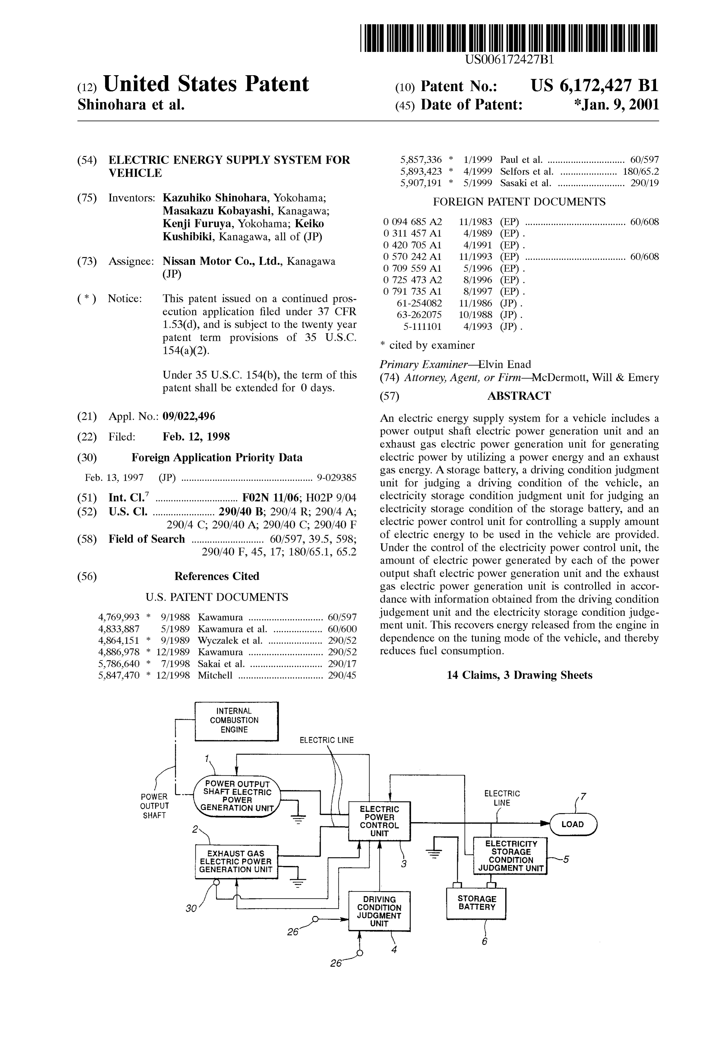
electricity Storage condition of the Storage battery, the 45 According to the certain embodiments of the invention, energy released from the driving Source of the vehicle can be when there arises, for example, an abnormality or a dete recovered without waste so as to be effectively utilized as rioration in the exhaust gas electric power generator, electric electric energy. The invention largely reduces energy con power generation can be accomplished by operating the Sumption in the driving Source. power output shaft electric power generator as a main Another advantage is that the kinetic energy and the 50 electric electric power generating Source. This can Stably Supply an power required for the vehicle, thereby improving exhaust gas energy obtained from the internal combustion the reliability of the electric energy Supply System. engine is effectively recovered in accordance with the run ning modes of the vehicle and the electricity Storage con The foregoing and other features, aspects and advantages dition of the electricity Storing means So as to be utilized as of the present invention will become more apparent from the electric energy. The fuel to be consumed in the internal 55 following detailed description of the present invention when combustion engine can be reduced, thereby attaining taken in conjunction with the accompanying drawings. improvements in fuel economy. BRIEF DESCRIPTION OF THE DRAWINGS Additionally, the thermal energy of exhaust gas dis charged from the internal combustion engine can be recov FIG. 1 is a block diagram of an electric energy Supply ered by the relatively simple construction of certain embodi 60 System of a vehicle, according to an embodiment of the ments of the invention, thereby not only attaining the fuel present invention.
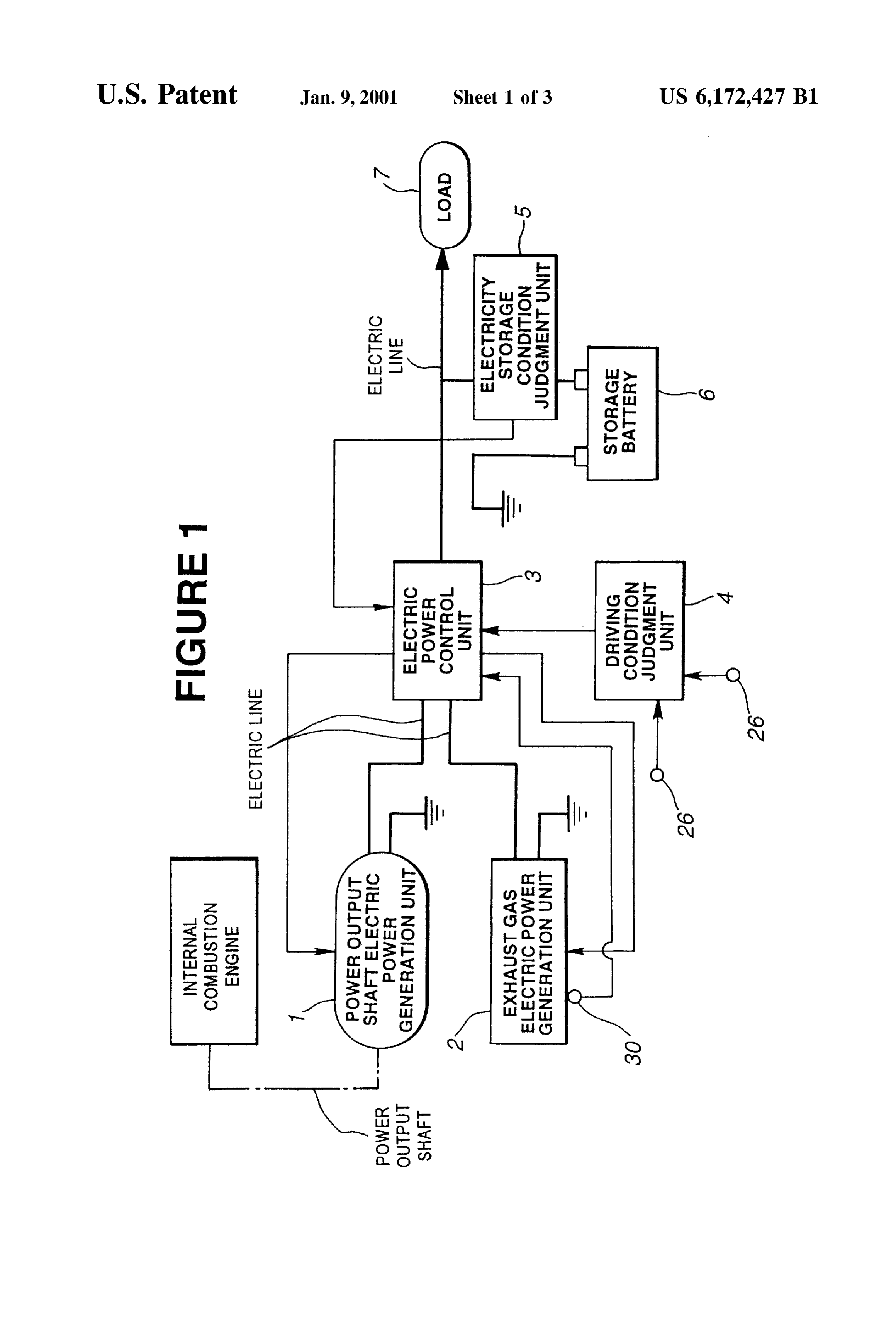
economy improvement but also making the improvement FIG. 2 is a perspective exterior view of a thermoelectric practical. generator forming part of the electric energy Supply System According to certain embodiments of the electric energy of a vehicle, according to an embodiment of the present Supply System for a vehicle, Since the turbine generator 65 invention.
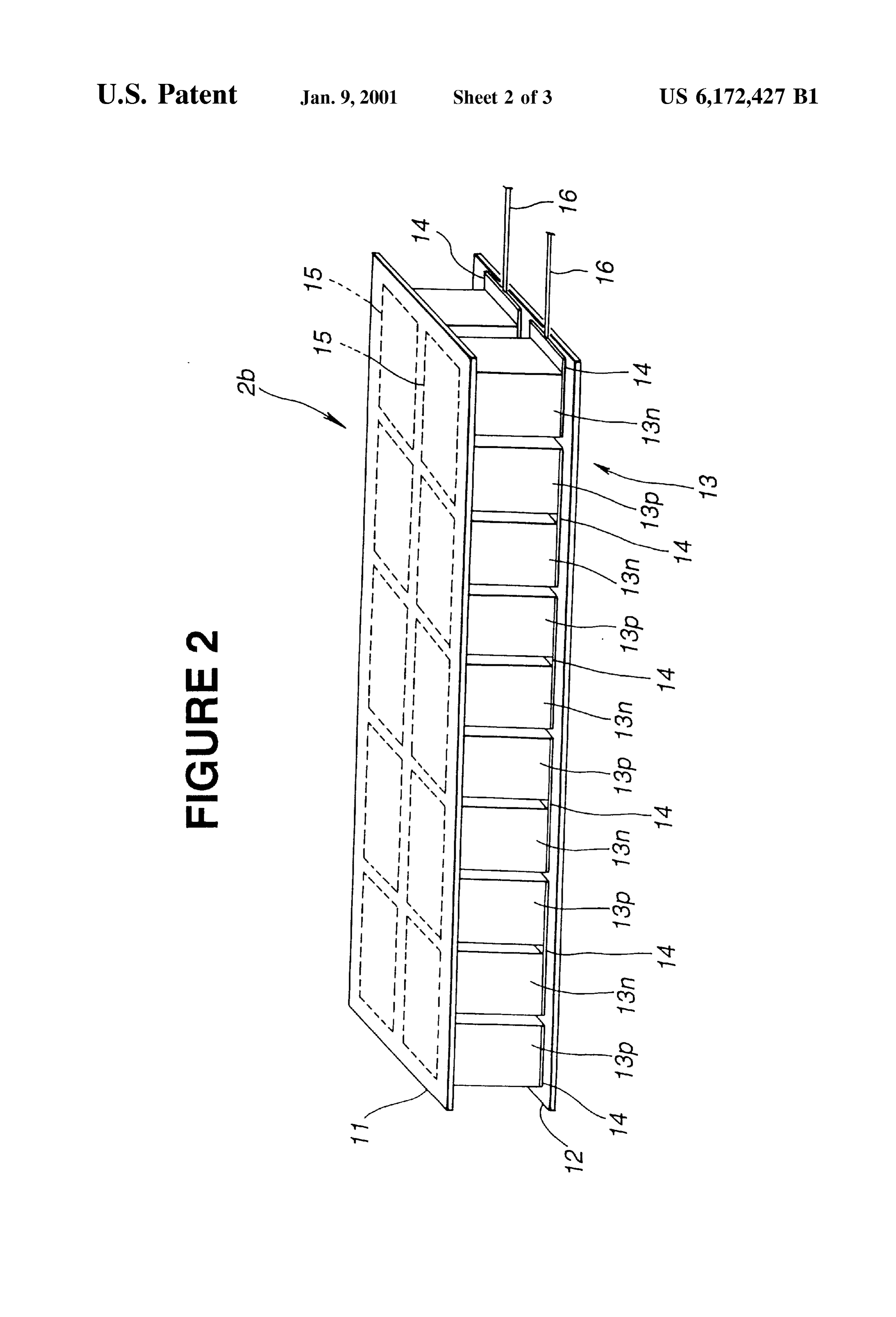
utilizing the kinetic energy of exhaust gas discharged from FIG. 3 is a graph of electric power generation character the internal combustion engine is used, energy to be dis istics of the thermoelectric generator forming part of the
Page 7
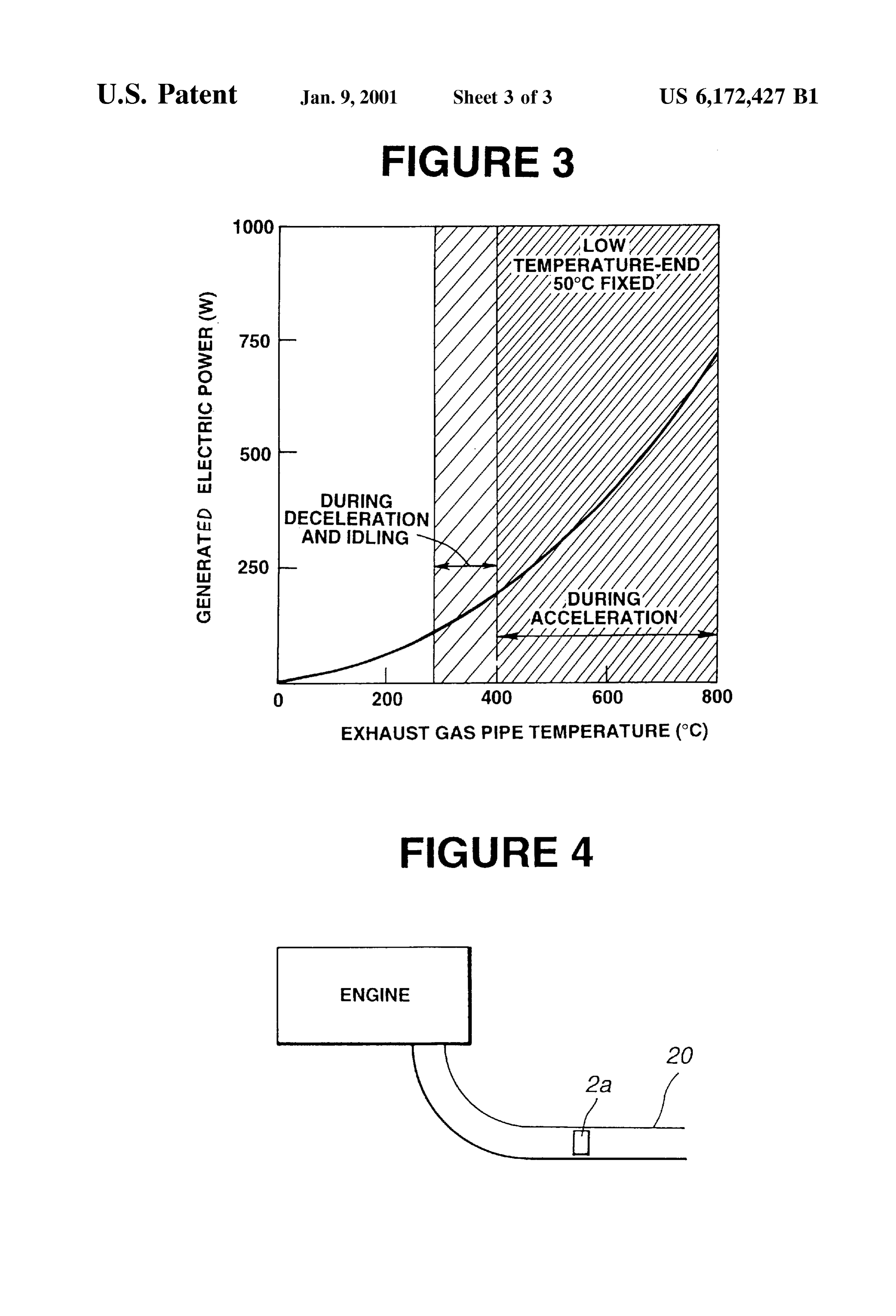
S 6 electric energy Supply System of a vehicle, according to an high temperature Source while outside air or another embodiment of the present invention. medium is used as the low temperature Source. In Still FIG. 4 is a Schematic view of a turbine generator forming further embodiments, the exhaust gas power generation unit part of the electric energy Supply System of a vehicle, 2 is provided with both the turbine generator and the according to another embodiment of the present invention. thermoelectric generator.
The thermoelectric generator will be discussed in greater
DETAILED DESCRIPTION OF EXEMPLARY detail below. FIG. 2 is a perspective view showing a part (a EMBODIMENTS module) of the thermoelectric generator 2b. As shown in this figure, the thermoelectric generator 2b includes a high
FIG. 1 is a block diagram showing a general arrangement temperature-side base plate 11 for effectively absorbing heat of the electric energy Supply System for a vehicle, according of the exhaust gas of the engine, a low temperature-side base to the present invention. This Supply System comprises a plate 12 which is located at a low temperature end-side and power output shaft power generation unit 1, Serving as an cooled by water or air; electrodes 14, 15; and lead wires 16. electric power generator drivingly connected to a power Each thermoelectric converter element couple 13 output shaft of an engine through a gear, a belt or the like. 15 includes, for example, a pair formed by a N-type Semicon An exhaust gas electric power generator unit 2 Serves as an ductor element 13 and a P-type Semiconductor element electric power generator for deriving electric energy from an 13. Ten pairs of the elements 13, 13 are connected in exhaust gas energy of the engine. A driving condition Series with each other to form the module Serving as one judgment unit 4 Serves as a vehicle driving condition judg electric power generation unit within the exhaust gas power ing means. An electric power control unit 3 Serves as electric generation unit 2. In certain embodiments, the thermoelec power controlling means for controlling an electric power tric generator 2b includes 100 units of such electric power generated by each electric power generating means in accor modules which are combined in Series with each other. dance with an electric power amount to be used in the Examples of the material of the thermoelectric converting vehicle and on the basis of information obtained from an element 13 are a crystal and a Sintered body of an alloy Such electricity Storage condition judgment unit 5 Serving as 25 as Silicon germanium, lead tellurium, bismuth tellurium, electricity Storage condition judging means for judging an cobalt antimony, and the like. Additionally, the number of electricity Storage amount of a Storage battery. The Storage the thermoelectric converter element couples 13 contained battery 6 Serves as an electricity Storing means which can in the electric power generating module Serving as the accumulate electric power obtained from each electric electric power generation unit is not limited to 10, and power generating means. therefore the number may be a desirable number as occasion In an exemplary embodiment, an alternator is used as an demands. The number of the electric power generating example of the output shaft electric power generation unit modules is not limited to 100, and therefore the number is Serving as one of the electric power generating means. This Set to a desirable number as occasion demands. Additionally, alternator 1 has Self-current limiting characteristics, in concerning the shape of the thermoelectric generator 2b, the which its maximum output current is generally designed 35 generator of the flat shape is shown in FIG. 2; however, the within a range where the alternator cannot burn, and there shape is not limited to that, and therefore the generator may fore it is unnecessary to provide a current limiting regulator. be cylindrical to be fitted to the exhaust gas pipe of the However, the current obtained by this alternator is engine or may be box-shaped to be fitted to a catalytic alternating, and therefore it is necessary to rectify the current converter if the generator is installed near the catalytic to obtain a constant-voltage in order to convert the current 40 COnVerter.
to electric power which can be used for the vehicle. In view As shown in FIG. 3, under an idling condition of the of this, a Voltage regulator is generally incorporated inte engine, the exhaust gas heat of the engine is less So that the grally in the alternator; however, this function may instead temperature of the exhaust gas pipe is about 300° C. to 400 be incorporated in the electric power control unit 3. The C. at a position near and downstream of the catalytic alternator 1 is adapted to be able to control its electric power 45 converter located under a vehicle floor. Additionally, the generating amount by controlling its induced current. temperature of the exhaust gas pipe at a position near and The output shaft electric power generation unit 1 Serving downstream of an exhaust manifold of the engine is higher as the output shaft electric power generating means is not than the above and is about 400° C. to 600 C. limited to the above-mentioned alternator. For example, in When the thermoelectric generator 2b is installed on the other embodiments it is an induction generator which is 50 exhaust gas pipe located in an under-floor region of the Separately disposed and adapted to generate electric power vehicle, there is the possibility of causing a capacity short by using a power energy obtained from the power output age for supplying about 200 to 300 W which is steadily shaft of the engine. The output shaft electric power genera required in the vehicle, under the idling condition. tion unit 1 may be a Single unit that combines an alternator In contrast, during acceleration or the like of the vehicle, and an induction generator. 55 the temperature of the exhaust gas pipe rises to about 400 The exhaust gas electric power generation unit 2 Serving C. to 800° C., so that it is possible to sufficiently supply an as one of the electric power generators is a turbine generator electric power required in the vehicle, only by the thermo 2a, in certain embodiments. The turbine generator 2a (See electric generator 2b.
FIG. 4) is installed in an exhaust gas pipe of the engine and It is possible to constitute the thermoelectric generator by adapted to rotate a turbine by kinetic energy of exhaust gas 60 providing more thermoelectric converter elements in order of the engine. In other embodiments, the exhaust gas power to compensate an electric power shortage in case the exhaust generator unit 2 is a thermoelectric generator 2b which gas pipe is low in temperature. However, it is preferable that includes a plurality of thermoelectric converter element the number of the elements are approximately the earlier couples and is adapted to generate electric power by described number from the view point of installing the employing the Seebeck effect due to a temperature differ 65 generator on the vehicle.
ence between a high temperature Source and a low tempera By providing a Voltage converting function to the ther ture Source. The heat energy of exhaust gas is used as the moelectric generator 2b, a Setting is made to always obtain
Page 8
the maximum electric power generating efficiency thereby battery. Additionally, a Voltage which makes it possible to attaining a higher thermoelectric generation efficiency. restart the engine during cold time is required as a lowest In the case where the Voltage of the Storage battery 6 is Voltage Vmin of the Storage battery. In case of the Storage higher than that of this thermoelectric generator 2b under a battery of the 12 volt system, this value is about 10.5 V. A condition in which the temperature of the exhaust gas pipe highest Voltage Vmax if the Storage battery is fully charged is low immediately after engine Starting, the current Stored is about 13.5 V to 15 V for a storage battery in a 12V system. in the Storage battery 6 flows in a reverse direction toward The lowest voltage Vmin and highest voltage Vmax the thermoelectric generator 2b. A function for preventing depend on the outside air temperature and the deterioration this occurrence is incorporated in the electric power control condition of the Storage battery 6 itself, and therefore a unit 3, in certain embodiments. 1O further suitable control for the electric power is made The turbine generator 2a for generating electric power by possible by changing a set value (not only the above using kinetic energy of exhaust gas may be employed as the mentioned voltage value) in accordance with conditions. exhaust gas electric power generation unit 2. A Schematic The deterioration condition of the Storage battery is judged depiction of a turbine generator 2a installed in an exhaust by measuring the value of the voltage (V) and the value of gas pipe 20 is provided in FIG. 4. In certain embodiments, 15 the current (I).
the turbine generator 2a is a So-called induction generator Although the electric power control unit 3, the driving which generates an induced current under rotation of a condition judgement unit 4 and the electricity Storage con rotatable shaft of the turbine upon impingement of exhaust dition judgment unit 5 which are connected between the gas against the turbine blades. In this case, its installation electric power generating means 1, 2 and the electric load 7 location is preferably positioned as upstream in the exhaust gas pipe 20 as possible or near the exhaust manifold 22. In of the vehicle have been shown in FIG. 1 as being disposed other words, by disposing the turbine generator 2a as near to Separate from each other, these functions of these units 3, 4, the engine as possible, it is possible to effectively utilize 5 are combined into an integral unit at one location, in high Speed exhaust gas or exhaust gas high in kinetic energy, certain embodiments. Each unit 3, 4, 5 or a combined unit, thereby accomplishing highly efficient electric power gen may be realized by control logic or a Suitable processing eration. 25 device, as is known in the art.
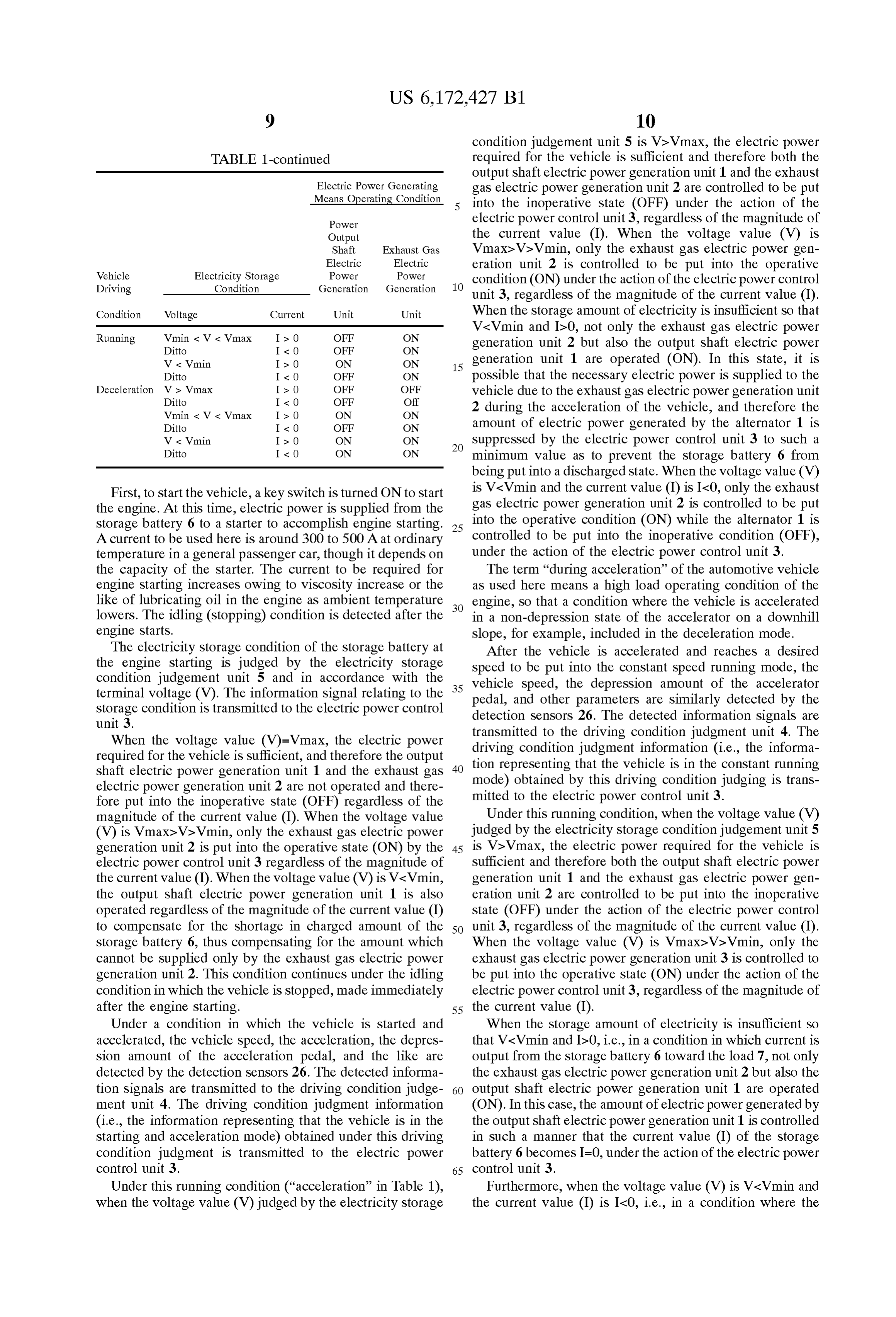
Since the kinetic energy of exhaust gas is utilized, the The operation of the electric energy Supply System energy of exhaust gas can be effectively utilized regardless according to this embodiment for a System applied to an of the temperature of exhaust gas as compared with the automotive vehicle will be discussed with reference to Table above-mentioned thermoelectric generator 2b, because high 1. Table 1 shows an example of controlling the operative Speed exhaust gas can be obtained in a running mode at a state (ON) and the inoperative state (OFF) of the power high engine Speed even under a low temperature condition output Shaft electric power generation unit 1 and the exhaust immediately after engine Starting. gas electric power generation unit 2, these units 1, 2 Serving Controlling the amount of electric power generated by the as electric power generating means under the control of the turbine generator 2a is made possible by controlling the electric power control unit 3. The control of electric power induced current of the turbine generator Similarly to that of 35 generator is made in accordance with the value of the the alternator.
terminal Voltage (V) and the current (I) of the storage battery
The current obtained by the turbine generator 2a is 6, obtained by the electricity Storage condition judgment alternating, and therefore it is necessary to rectify the current unit 5, for example, in each of the four modes, i.e., the to obtain a constant-voltage in order to convert the current Stopping (idling) mode, the acceleration mode, the constant to electric power which can be used for the vehicle, as is 40 Speed running mode, and the deceleration mode. The four done in the case of the alternator. Accordingly, this function modes are judged (i.e., determined) by the driving condition may be incorporated in the electric power control unit 3.
The driving condition judgment unit 4 Serving as the judgement unit 4 of the vehicle.
driving condition judging means for the vehicle, forming TABLE 1.
part of this system will be explained. The driving condition 45 judgement unit 4 is arranged as follows. Detection Sensors Electric Power Generating 26 are provided that detect respectively, for example, the Means Operating Condition Speed of the vehicle, acceleration of the vehicle, engine
Speed, a depression amount of an accelerator pedal, a Power Output depression amount of a brake pedal, a gear position of a 50 Shaft Exhaust Gas transmission, a combustion condition (for example, a com Electric Electric bustion chamber temperature, presence or absence of knock Vehicle Electricity Storage Power Power ing and the like), an exhaust gas temperature, an intake air Driving Condition Generation Generation temperature, a fuel Supply amount, an outside air Condition Voltage Current Unit Unit temperature, atmospheric pressure, and fluctuating values of 55 these conditions. The information obtained by one or more Stopping W = Wimax Is O OFF OFF of these detection Sensors are judged to decide in which (During Ditto I&O OFF OFF mode (i.e., a stopping (idling) mode, a starting or accelera Idling) Wmin & W & Vmax Is O OFF ON tion mode, a constant Speed running mode, a deceleration Ditto
W & Vimin
OFF
mode) the vehicle is currently operating. Ditto I&O ON ON The electricity Storage condition judgment unit 5, which 60 Acceleration V > Vmax
can Serve as the electricity Storage condition judging means, Ditto I < 0- OFF OFF judges the electricity Storage condition, for example, in Wmin & W & Vmax
Ditto
OFF
OFF
accordance with the voltage (V) of the Storage battery 6, W & Vimin Is O ON ON input and output current (I), the temperature of the Storage Ditto I&O OFF ON battery and other factors. 65 Constant Vs. Vmax Is O OFF OFF Here, I>0 means the output of current from the Storage Speed Ditto I&O OFF OFF battery, while I-0 means the input of current to the Storage
Page 9
condition judgement unit 5 is V>Vmax, the electric power
TABLE 1-continued required for the vehicle is sufficient and therefore both the output Shaft electric power generation unit 1 and the exhaust
Electric Power Generating gas electric power generation unit 2 are controlled to be put
Means Operating Condition into the inoperative state (OFF) under the action of the
Power electric power control unit 3, regardless of the magnitude of
Output the current value (I). When the voltage value (V) is
Shaft Exhaust Gas Vmax>V>Vmin, only the exhaust gas electric power gen
Vehicle Electricity Storage
Electric
Power
Electric
Power eration unit 2 is controlled to be put into the operative
Driving Condition Generation Generation 1O condition (ON) under the action of the electric power control unit 3, regardless of the magnitude of the current value (I).
Condition Voltage Current Unit Unit When the storage amount of electricity is insufficient so that Running Wmin & W & Vmax Is O OFF ON
V<Vmin and Id-0, not only the exhaust gas electric power
generation unit 2 but also the output shaft electric power
W & Vimin Is O ON ON 15 generation unit 1 are operated (ON). In this state, it is Ditto I&O OFF ON possible that the necessary electric power is Supplied to the Deceleration V > Vmax
Ditto
OFF
OFF
OFF
Off vehicle due to the exhaust gas electric power generation unit
Wmin & W & Vmax Is O ON ON 2 during the acceleration of the vehicle, and therefore the Ditto I&O OFF ON amount of electric power generated by the alternator 1 is W & Vimin Is O ON ON Suppressed by the electric power control unit 3 to Such a Ditto I&O ON ON minimum value as to prevent the Storage battery 6 from being put into a discharged State. When the Voltage value (V)
First, to start the vehicle, a key switch is turned ON to start is V-Vmin and the current value (I) is I-0, only the exhaust the engine. At this time, electric power is Supplied from the gas electric power generation unit 2 is controlled to be put Storage battery 6 to a starter to accomplish engine Starting. 25 into the operative condition (ON) while the alternator 1 is A current to be used here is around 300 to 500 A at ordinary controlled to be put into the inoperative condition (OFF), temperature in a general passenger car, though it depends on under the action of the electric power control unit 3. the capacity of the Starter. The current to be required for The term “during acceleration” of the automotive vehicle engine Starting increases owing to Viscosity increase or the as used here means a high load operating condition of the like of lubricating oil in the engine as ambient temperature engine, So that a condition where the vehicle is accelerated lowers. The idling (stopping) condition is detected after the in a non-depression State of the accelerator on a downhill engine Starts. Slope, for example, included in the deceleration mode. The electricity Storage condition of the Storage battery at After the vehicle is accelerated and reaches a desired the engine starting is judged by the electricity storage Speed to be put into the constant Speed running mode, the condition judgement unit 5 and in accordance with the terminal voltage (V). The information signal relating to the 35 vehicle pedal,
Speed, the depression amount of the accelerator and other parameters are similarly detected by the
Storage condition is transmitted to the electric power control detection Sensors 26. The detected information Signals are unit 3.
transmitted to
When the voltage value (V)=Vmax, the electric power driving condition judgment the driving condition judgment unit 4. The information (i.e., the informa required for the vehicle is Sufficient, and therefore the output tion representing that the vehicle shaft electric power generation unit 1 and the exhaust gas 40 mode) obtained by this driving condition is in the constant running electric power generation unit 2 are not operated and there judging is trans fore put into the inoperative state (OFF) regardless of the mitted to the electric power control unit 3. magnitude of the current value (I). When the voltage value Under this running condition, when the Voltage value (V) (V) is VmaxcV>Vmin, only the exhaust gas electric power judged by the electricity Storage condition judgement unit 5 generation unit 2 is put into the operative State (ON) by the 45 is V>Vmax, the electric power required for the vehicle is electric power control unit 3 regardless of the magnitude of sufficient and therefore both the output shaft electric power the current value (I). When the voltage value (V) is V-Vmin, generation unit 1 and the exhaust gas electric power gen the output shaft electric power generation unit 1 is also eration unit 2 are controlled to be put into the inoperative operated regardless of the magnitude of the current value (I) state (OFF) under the action of the electric power control to compensate for the Shortage in charged amount of the 50 unit 3, regardless of the magnitude of the current value (I). Storage battery 6, thus compensating for the amount which When the voltage value (V) is VmaxcV>Vmin, only the cannot be Supplied only by the exhaust gas electric power exhaust gas electric power generation unit 3 is controlled to generation unit 2. This condition continues under the idling be put into the operative state (ON) under the action of the condition in which the vehicle is stopped, made immediately electric power control unit 3, regardless of the magnitude of after the engine Starting. 55 the current value (I).
Under a condition in which the vehicle is started and When the storage amount of electricity is insufficient so accelerated, the vehicle Speed, the acceleration, the depres that V-Vmin and I>0, i.e., in a condition in which current is Sion amount of the acceleration pedal, and the like are output from the storage battery 6 toward the load 7, not only detected by the detection sensors 26. The detected informa the exhaust gas electric power generation unit 2 but also the tion signals are transmitted to the driving condition judge 60 output shaft electric power generation unit 1 are operated ment unit 4. The driving condition judgment information (ON). In this case, the amount of electric power generated by (i.e., the information representing that the vehicle is in the the output shaft electric power generation unit 1 is controlled Starting and acceleration mode) obtained under this driving in Such a manner that the current value (I) of the Storage condition judgment is transmitted to the electric power battery 6 becomes I=0, under the action of the electric power control unit 3. 65 control unit 3.
Under this running condition (“acceleration” in Table 1), Furthermore, when the voltage value (V) is V-Vmin and when the voltage value (V) judged by the electricity Storage the current value (I) is I-0, i.e., in a condition where the
Page 10
current is input toward the Storage battery 6, only the parameters. Accordingly, an abnormality and a deterioration exhaust gas electric power generation unit 2 is controlled to condition of the thermoelectric generator 2b can be detected be put into the operative state (ON) while the output shaft by the difference between this calculated output electric electric power generation unit 1 is controlled to be put into power and an actual output electric power. By adding the inoperative state (OFF). detecting means 30 for this (FIG. 2), electric power supply When the vehicle is in a decelerated running condition, is changed over to be provided by the output shaft electric desired parameters of the vehicle Speed, the acceleration, the power generation unit 1 under the action of the electric depression amount of the accelerator pedal, the depression power control unit 3. This is done, for example, when the amount of the brake pedal, the fuel Supply amount, the thermoelectric generator loses its electric power generating engine Speed and other parameters are Similarly detected by ability arises, thereby ensuring an electric power Supply to the detection Sensors 26. The detected information signals the vehicle. This makes the electric energy Supply System of are transmitted to the driving condition judgment unit 4. The the present invention further practical and highly reliable. driving condition judgment information (i.e., the informa Although an exemplary embodiment has been described tion representing that the vehicle is in the deceleration in which the electric energy Supply System of the present mode) is transmitted to the electric power control unit 3. 15 invention is mounted on a gasoline-fueled engine, the Under this running condition, when the Voltage value (V) present invention is not limited to utilizing the exhaust gas judged by the electricity Storage condition judgment unit 5 energy emitted from gasoline-fueled engines and therefore is is V&Vmax, both the output shaft electric power generation also effective for utilizing exhaust gas energy of a diesel unit 1 and the exhaust gas electric power generation unit 2 engine. In an electric Vehicle using an electric motor as a are controlled to be put into the inoperative condition (OFF) driving Source, heat generation from the electric motor by the electric power control unit 3. during the Starting, acceleration and the like of the electric Additionally, when the voltage value (V) is vehicle can be utilized as a heat Source, thereby similarly Vmax>V>Vmin and the current value (I) is I>0, i.e., in a making it possible to effectively utilize energy. Additionally, condition where current is output from the Storage battery 6 25 the vehicle to which the electric energy Supply System of the to the load 7, the exhaust gas electric power generation unit present invention is applied is not limited to automotive 2 is controlled to be put into the operative state (ON) and the vehicles, and therefore can be applied to motorcycles and output shaft electric power generation unit 1 is operated other vehicles similar to them.
(ON). This is done for the following reasons. The energy In the exemplary embodiment, there arises an electric amount of exhaust gas is low during the deceleration Similar power generation amount-excessive condition in which the to stopping of the vehicle So that the electric power obtained voltage value (V) becomes V>Vmax during the acceleration only from the exhaust gas electric power generation unit 2 and running of the vehicle, in which Such an excessive is insufficient. Therefore, the electric power control unit 3 electric power is not effectively utilized. Accordingly, in controls in Such a manner that the electric power generation order to effectively utilize this excessive electric power, the by the output shaft electric power generation unit 2 becomes 35 output shaft electric power generation unit 1 Such as the the maximum So as to put the Storage battery 6 into the fully alternator itself is arranged as a prime mover having an charged State. electric power generating function, or Separately providing Furthermore, when the voltage value (V) is a prime mover, thereby making it possible to reduce engine Vmax>V>Vmin and the current value (I) is I-0, i.e., in a load during acceleration and running. This improves accel condition where current is input toward the Storage battery 40 eration performance and fuel economy of the vehicle. 6, the output shaft electric power generation unit 1 is When the thermoelectric generator 2b is the exhaust gas controlled to be put into the inoperative state (OFF) so that electric power generation unit 2, it is possible to positively no electric power generation by this unit is accomplished, control the temperature of exhaust gas by using the Peltier while only the exhaust gas electric power generation unit 2 effect of the generation unit. For example, when the ther is controlled to be put into the operative state (ON). 45 moelectric generator 2b is disposed upstream of a catalytic
Furthermore, when the voltage value (V) is V-Vmin, the converter, exhaust gas is heated by Supplying electric power charged amount of the Storage battery 6 is insufficient, and to the thermoelectric generator 2b in a condition where the therefore both the output Shaft electric power generation unit temperature of the catalytic converter is low and the tem 1 and the exhaust gas electric power generation unit 2 are perature of the exhaust gas is low. This enhances a reaction controlled to be put into the operative state (ON) by the 50 ability of a catalyst thus making it possible to enhance an electric power control unit 3. Under this condition, the exhaust gas purification performance.
kinetic energy during vehicle running is recovered as elec In a high load operating condition in which the tempera tric power. ture of exhaust gas is considerably high, it is possible to The programming of the electric power control unit 3 to lower and Suitably control the temperature of exhaust gas by control the ON/OFF states of the power output shaft electric 55 utilizing the Peltier effect. This can improve the reliability of power generation unit 1 and the exhaust gas electric power an exhaust System.
generation unit 2 is readily accomplished by one of skill in Although the present invention has been described and the art, given Table 1 as provided. illustrated in detail, it is to be clearly understood that the In case of using the thermoelectric generator 21b as the Same is by of illustration and example only and is not to be exhaust gas electric power generation unit of the above 60 taken by way of limitations, the Spirit and Scope of the mentioned System, the output electric power generated by present invention being limited only by the terms of the the generator 2b can be previously calculated in accordance appended claims.
with the heat quantity of exhaust gas passing through the What is claimed is:
exhaust gas pipe, the flow Speed of the exhaust gas, the heat 1. An electric power control System for a vehicle, com quantity emitted to the atmospheric air, the high 65 prising:
temperature-end temperature and the low temperature-end an internal combustion engine for driving vehicle, the temperature of the thermoelectric generator 2b, and other engine having an exhaust gas passage;
Page 11
an electric load disposed in the vehicle; a plurality of electric power generating units for gener a first electric generator driven by kinetic energy output ating electric power by utilizing, different energies from a power output Shaft of the engine, the first which are derived from a driving Source for driving the electric generator comprising an alternator mechani Vehicle, including at least a first electric power genera cally driven by the engine; tor driven by kinetic energy output from a power output a Second electric generator driven by energy of exhaust shaft of the engine and a Second electric generator gas from the engine, the Second electric generator driven by energy of exhaust gas from the engine, the comprising a thermoelectric converter that generates driving Source including an internal combustion electricity from energy of engine exhaust gas, the engine, the plurality of the electric power generating thermoelectric converter being disposed in the exhaust 1O units including an alternator for generating electric gas passage So as to be exposed to exhaust gas flowing power by utilizing a power energy mechanically therethrough; obtained from the internal combustion engine, and an a storage battery; exhaust gas electric power generator for generating an electric line connecting the electric load, the first and electric power by utilizing exhaust gas energy of the the Second electric generators and the battery to con 15 internal combustion engine, the exhaust gas electric duct the electric power therebetween; power generating unit being a thermoelectric generator an electricity Storage condition judgment unit that deter for generating electric power by utilizing the heat mines a charge condition of the Storage battery in energy of exhaust gas discharged from the internal accordance with both Voltage of the Storage battery and combustion engine;
one of input of current to and output of current from the an electricity Storing device for Storing electric energy; Storage battery; a driving condition judging unit for judging a driving a driving condition judgment unit that determines the condition of the vehicle;
driving condition of the vehicle; and an electricity Storage condition judging unit for Judging an electric power control unit, coupled to the electricity an electricity Storage condition within the electricity Storage condition judgment unit and the driving con 25 Storing unit; and dition judgment unit, the electric power control unit an electric power control unit for controlling a Supply controlling both the first electric generator and the amount of electric energy to be used in the vehicle, by Second electric generator as a function of the deter controlling an amount of electric power generated by mined Storage condition of the battery and the deter each of the plurality of the electric power generating mined driving condition of the vehicle in Such a manner units in accordance with information received from the that the first electric generator and the Second electric driving condition judging unit and the electricity Stor generator are activated under different conditions. age condition judging unit.
2. The electric power control System of claim 1, wherein 11. The electric energy Supply System of claim 10, the electric power control unit is configured to activate the wherein the electric power control unit is configured to Second electric generator unless the battery is charged at 35 operate the exhaust gas electric power generating unit as a least to a specified level. main generating Source to generate electric power and to 3. The electric power control system of claim 2, wherein Supply an electric energy obtained by this electric power the electric power control unit is configured to Stop the first generation to the electricity Storing device and to an electric electric generator when the electric load is large and the power load within the vehicle, when the vehicle is in an Storage battery is discharging electricity. 40 acceleration condition as detected by the driving condition 4. The electric power control system of claim 3, wherein judging unit.
the electric power control unit is configured to activate the 12. The electric energy Supply System of claim 11, first and Second electric generators when the vehicle is wherein the electric power control unit is configured to running in a high load condition. operate the alternator as a main generating Source to gen 5. The electric power control system of claim 4, wherein 45 erate electric power and to Supply an electric energy the high load condition is acceleration of the vehicle. obtained by this electric power generation to the electricity 6. The electric power control system of claim 5, wherein when Storing unit and to an electric power load within the vehicle, the electric power control unit is configured to activate the the vehicle is in an acceleration condition as detected Second electric generator to generate a Substantially maxi by the driving condition judging unit. mum electric power, and activate the first electric generator 50 13. The electric energy Supply System of claim 12, further to add auxiliary power. comprising a detecting unit for detecting an electric power 7. The electric power control system of claim 6, wherein generating ability of the exhaust gas electric power gener the electric power control unit is configured to activate the ating unit, and in that the electric power control unit is first electric generator to generate more electric power when configured to operate the power output shaft electric power the determined driving condition indicates that the load of 55 generating electric unit as a main generating Source when the power generating ability detected by the detecting the vehicle is light and less electric power when the load of the vehicle is heavy. device is equal to or less than a predetermined level. 8. The electric power control system of claim 7, wherein 14. An electric power control System for a vehicle, the electric power control unit is configured to activate the comprising:
first electric generator and the Second electric generator 60 an internal combustion engine for driving the vehicle, the when the charge of the battery is below a specified level. engine having an exhaust gas passage through which 9. The electric power control system of claim 8, wherein exhaust gas from the engine flows; the electric power control unit is configured to prohibit an electric load disposed in the vehicle; operation of the first and Second electric generators when the a first electric generator driven by kinetic energy output battery is charged at least to a specified level. 65 from a power output Shaft of the engine, the first 10. An electric energy Supply System for a vehicle, electric generator being an alternator driven by revo comprising: lution of the engine;
Page 12
a Second electric generator driven by energy of exhaust a driving condition judgment unit that determines the gas from the engine, the Second electric generator being driving condition of the vehicle; and a thermoelectric converter that generates electricity an electric power control unit, coupled to the electricity from energy of engine exhaust gas, the thermoelectric converter being operatively disposed in the exhaust gas 5 Storage condition judgment unit and the driving con passage, dition judgment unit, the electric power control unit a storage battery; controlling both the first electric generator and the an electric line connecting the electric load, the first and Second electric generator as a function of the deter the Second electric generators and the battery to con 1O mined Storage condition of the battery and the deter duct the electric power therebetween; mined driving condition of the vehicle in Such a manner an electric Storage condition judgment unit that deter the first electric generator is deactivated while the mines a change condition of the Storage battery in Second electric generator is activated, in accordance accordance with both Voltage of the Storage battery and with the determined driving condition of the vehicle. one of input of current to and output to current from the
Storage battery;

Provenance
- Collection
- Cited prior art
- Original PDF
- patentimages.storage.googleapis.com →
- Filed
- 1998-02-12
- Pages
- 12
- Method
- pdftotext (the PDF's own text layer) + pdftoppm 300dpi page scans
- Source
- Google Patents bibliographic record
- Granted
- 2001-01-09
- Inventors
- Kazuhiko Shinohara; Masakazu Kobayashi; Kenji Furuya; Keiko Kushibiki; Nissan Motor Co Ltd
- Transcribed from
- patentimages.storage.googleapis.com →