patent · US4047512
Electric fuel vaporizer
13 September 1977
Page 1 — bibliographic record
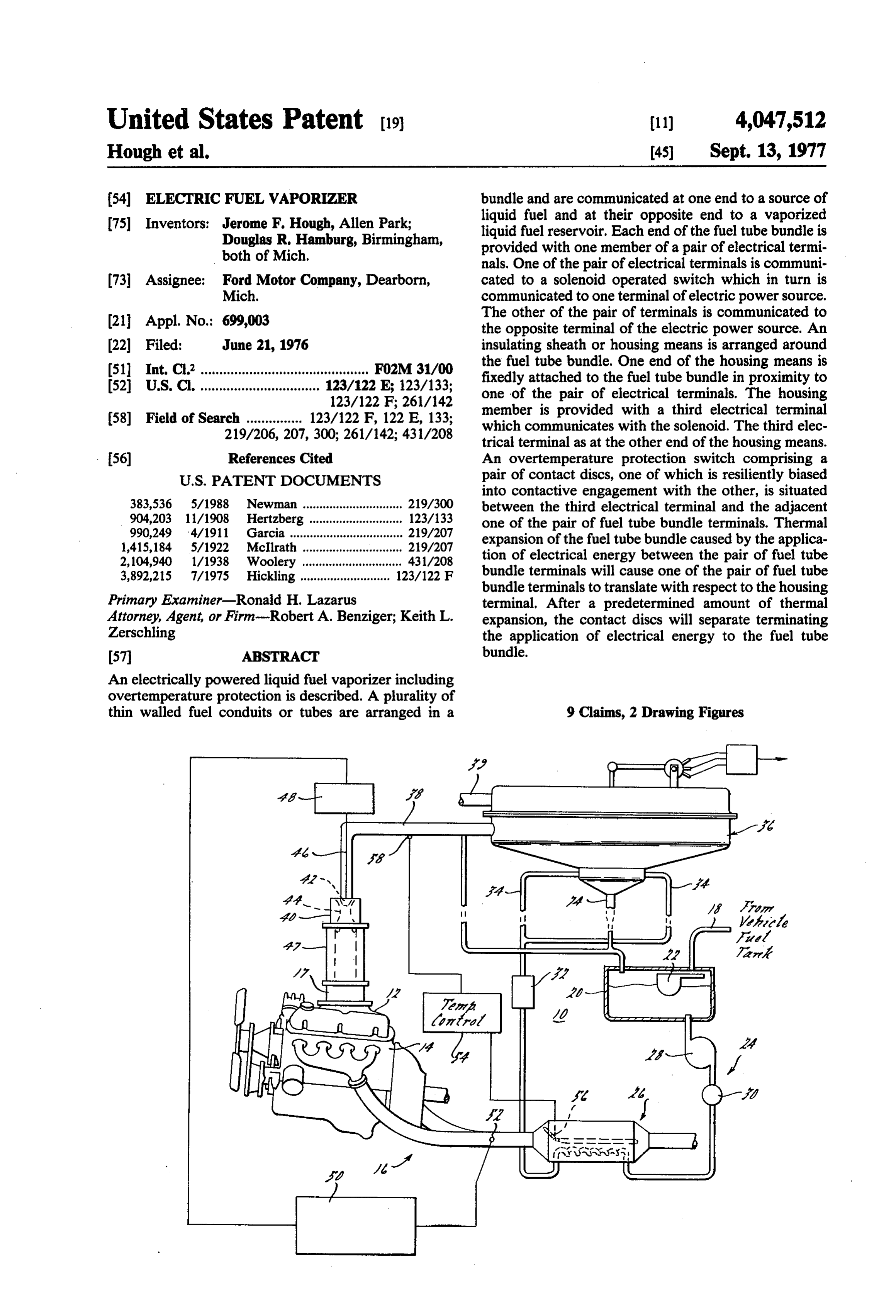
United States Patent (19) (11) 4,047,512 Hough et al. 45 Sept. 13, 1977 54 ELECTRICFUEL VAPORIZER bundle and are communicated at one end to a source of 75 Inventors: Jerome F. Hough, Allen Park; liquid fuel and at their opposite end to a vaporized Douglas R. Hamburg, Birmingham, liquid fuel reservoir. Each end of the fuel tube bundle is both of Mich. provided with one member of a pair of electrical termi nals. One of the pair of electrical terminals is communi 73) Assignee: Ford Motor Company, Dearborn, cated to a solenoid operated switch which in turn is Mich. communicated to one terminal of electric power source, 21 Appl. No.: 699,003 The other of the pair of terminals is communicated to the opposite terminal of the electric power source. An (22 Filed: June 21, 1976 insulating sheath or housing means is arranged around 511 Int. C.’............................................. F02M 31/00 the fuel tube bundle. One end of the housing means is 52 U.S. C. ................................ 123/122 E. 123/133; fixedly attached to the fuel tube bundle in proximity to 123/122 F; 261/142 one of the pair of electrical terminals. The housing 58 Field of Search ............... 123/122 F, 122 E, 133; member is provided with a third electrical terminal which communicates with the solenoid. The third elec 219/206, 207, 300; 261/142; 431/208 trical terminal as at the other end of the housing means. 56 References Cited An overtemperature protection switch comprising a
into contactive engagement with the other, is situated 383,536 5/1988 Newman .............................. 219/300 between the third electrical terminal and the adjacent 904,203 11/1908 Hertzberg. ... 123/133 one of the pair of fuel tube bundle terminals. Thermal 990,249 4/1911 Garcia .................................. 219/207 expansion of the fuel tube bundle caused by the applica 1,415,184 5/1922. McIlrath .............................. 219/207 tion of electrical energy between the pair of fuel tube 2,104,940 1/1938 Woolery .............................. 431/208 3,892,215 7/1975 Hickling ........................... 123/122 F bundle terminals will cause one of the pair of fuel tube bundle terminals to translate with respect to the housing
Primary Examiner-Ronald H. Lazarus terminal. After a predetermined amount of thermal Attorney, Agent, or Firm-Robert A. Benziger; Keith L. expansion, the contact discs will separate terminating Zerschling the application of electrical energy to the fuel tube 57 ABSTRACT bundle.
An electrically powered liquid fuel vaporizer including overtemperature protection is described. A plurality of thin walled fuel conduits or tubes are arranged in a 9 Claims, 2 Drawing Figures
Page 2
Drawing sheet — no readable text.
Page 3
ture. To the extent that the air/fuel ratio may be more
ELECTRICFUEL VAPORIZER accurately controlled, the ability to implement tech niques for the reduction of atmospheric pollutants gen
CROSS REFERENCE TO RELATED erated by the internal combustion engine may be in
This application is related to copending commonly The prior art contains a substantial number of sugges assigned patent application Ser. No. 660,281, filed on tions directed to the vaporization of a liquid fuel for use Feb. 23, 1976 in the names of J. E. Auiler et al. and titled in a fuel delivery system for an internal combustion "Vaporized Liquid Fuel Delivery and Metering Sys engine. However, the prior art has failed to address the tem'. 10 consideration of the vaporization of a liquid fuel for start-up of the internal combustion engine and has also
BACKGROUND OF THE INVENTION failed to address the consideration of vaporization of a 1. Field of the Invention liquid fuel in quantities sufficient to sustain engine oper The present invention is directed to the field of inter ation during the early phases of engine operation when nal combustion engine fuel delivery and metering sys 15 the heat generated by the engine is insufficient to pro tems generally. In particular, the present invention is mote vaporization of a liquid fuel. It is therefore a spe directed to that portion of the above-noted field which cific object of the present invention to provide an auxil is concerned with the delivery and metering of a liquid iary heater apparatus for converting a liquid fuel to a fuel into an air stream to provide a combustible air/fuel vapor in quantities sufficient to initiate and sustain en mixture for an internal combustion engine. More partic 20 gine operation during those phases of engine operation ularly still, the present invention is directed to that when the heat generated by the engine is insufficient to portion of the above-noted field which is concerned vaporize the liquid fuel. More particularly still, it is an with the delivery and metering into an air stream of a object of the present invention to provide such a device fuel which is a liquid at standard temperature and pres which may reliably generate substantial quantities of sure (STP) but which has been vaporized prior to mix 25 liquid fuel vapor within a short time period after initia ture with the air stream. More particularly still, the tion of heating. More particularly still, it is an object of present invention is directed to that portion of the the present invention to provide such a device which above-noted field which is concerned with the vapor will not create a hazard to the engine or to any automo ization of a vaporized liquid fuel for mixture with a tive vehicle with which the engine is associated. More stream of air in order to establish a combustible air/fuel 30 particularly still, it is an object of the present invention mixture. More particularly still, the present invention is to provide such a device which includes overtempera directed to that portion of the above-noted field which ture protection as a safeguard to prevent the device is concerned with the vaporization of a liquid fuel for an from generating quantities of heat in excess of that actu internal combustion engine under conditions in which ally required to generate the desired quantities of vapor the engine itself is not capable of generating substantial 35 ized liquid fuel. It is a further and specific object of the quantities of heat. More particularly still, the present present invention to provide such a device which may invention is directed to that portion of the above-noted be powered by the vehicle electrical system and which field which is concerned with the provision of an elec may be rendered operative only during those time pe trically operated liquid fuel vaporizer for providing riods when the auxiliary heater device is required as a quantities of vaporized liquid fuel sufficient to initiate liquid fuel vapor generator.
and sustain engine operation during that time period SUMMARY OF THE PRESENT INVENTION when engine operation does not generate sufficient quantities of heat, as a combustion by-product, to be The present invention provides an electrically oper useful in vaporizing a liquid fuel. ated liquid fuel vaporizer comprised of a plurality of 2. Description of the Prior Art 45 thin walled electrically conductive fuel tubes or con It is well known in the prior art to provide a fuel in duits. The auxiliary heater tubes are welded or other liquid form to a moving air stream for delivery to the wise fabricated into a unitary thermally cooperative combustion chambers of an internal combustion engine. unit having a relatively high surface-to-volume ratio The prior art systems generally have utilized mechani consonant with rapid heating of the fuel within the fuel cal or electromechanical fuel delivery and metering 50 tubes. The opposite ends of the fuel tube bundle are apparatus to provide metered quantities of liquid fuel in provided with means forming a pair of electrical termi proximity to, and in some cases into, the combustion nals. A thermally insulating housing means is provided chambers of an internal combustion engine. The prior in surrounding relationship to the fuel tube bundle. One art has also taught that a quantity of liquid fuel may be end of the housing means is fixedly attached to the fuel added to a quantity of moving air upstream from, and 55 tube bundle in proximity to a first member of the pair of for ultimate delivery to, a plurality of combustion electrical terminals. The opposite end of the housing chambers through a plurality of intake manifold con means is provided with a third electrical terminal. One duits. The advent of federally mandated internal com of the pair of fuel tube bundle terminals is communi bustion engine exhaust emission standards has resulted cated to one terminal of a voltage supply. The other of in the investigation of techniques to substantially reduce the pair of fuel tube bundle terminals is communicated the quantity of pollutants produced by an internal com to one terminal of a solenoid operated control switch bustion engine. One technique proposed to reduce the member. The other terminal of the solenoid operated quantity of atmospheric pollutants generated by an control switch member is connected to the power sup internal combustion engine has been to prevaporize the ply. The control switch is communicated to the housing liquid fuel prior to delivery to the air stream. The basis 65 member terminal.
of this proposal is the improved ability to control, from Means defining an overtemperature protection switch cylinder-to-cylinder within any one internal combus are arranged to intercommunicate the housing member tion engine, the air/fuel ratio of the combustion mix terminal with one of the pair of fuel tube bundle termi
Page 4
nals. These means comprise a pair of contact discs, one vapor reservoir 36. Auxiliary heating means 32 is de of which is fixedly connected to one of its associated scribed in greater detail hereinbelow with reference to terminal members and the other of which is resiliently FG, 2.
coupled to the other of its associated terminal members As illustrated in FIG. 1, the primary and auxiliary with means permitting limited relative movement of the heating means 26, 32 are connected in serial fluid flow resiliently biased contact disc member. On the applica relationship. In order for efficient operation of the auxil tion of heating energy, the length of the fuel tube bundle iary heating means 32, if should be designed for rela will increase due to thermal expansion. After a prede tively low fuel flow consonant with operation of the termined amount of length increase has occurred, the associated engine at idle. As such, however, the auxil resiliently biased spring disc member will reach its limit 10 iary heating means 32 could present a high impedance of travel and the spring disc members will separate to fluid flow and could impede engine operation under terminating the electric circuit which includes the sole high fuel consumption conditions. It is therefore con noid member. This will terminate the flow of electrical templated that the primary and auxiliary heating means energy through the fuel tube bundle to limit heating. could be connected in parallel fluid flow relationship. It 15 is also contemplated to provide a fluid by-pass valve
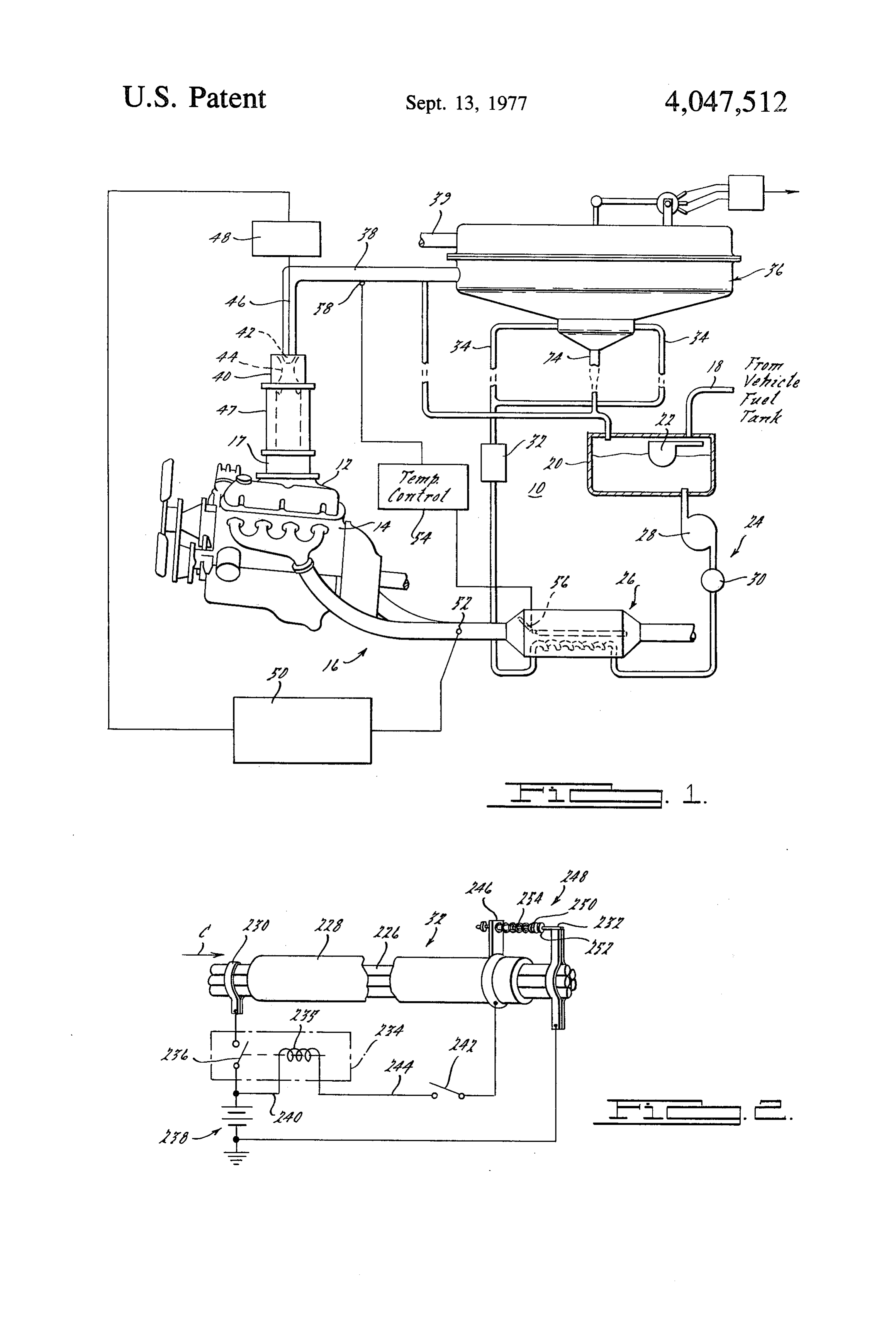
BRIEF DESCRIPTION OF THE DRAWING
downstream from primary heating means 26 and up
FIG. 1 is a schematic view which illustrates a vapor stream from the auxiliary heating means 32 to place the ized liquid fuel delivery and metering system with primary heating means 26 in direct fluid communication which the present invention is of utility. with the vapor reservoir 36 when the auxiliary heating FIG. 2 illustrates, in a diagrammatic view, the auxil 20 means 32 are not required as a vapor supply source. iary electrical liquid fuel vaporizing means according to Vapor reservoir. 36 is communicated by way of con the present invention. duit 38 with carburetor means 40. As used herein "car DETAILED DESCRIPTION OF THE buretor' means any device for mixing fuel with air to
establish a combustible air/fuel mixture. As illustrated in FIG. 1, the vapor delivery nozzle 42 of vapor deliv
Referring now to the drawing wherein like numerals ery conduit 38 is positioned within the low pressure designate like structure throughout the various views zone formed by the metering venturi means 44 of the thereof, FIG. 1 illustrates a vaporized liquid fuel deliv ery and metering system 10 which includes the electri carburetor means 40. A movable pintle 46 is situated cally operated liquid fuel vaporizer according to the 30 servomechanism delivery within the vapor nozzle 42 and is controlled by means 48. Carburetor means 40 in present invention. The vaporized liquid fuel delivery and metering system 10 is arranged to provide a com clude mixing section 47 which intercommunicates the metering venturi means 44 with the throttle body 17 and bustible air/fuel mixture to the intake manifold 12 of an the intake manifold 12.
internal combustion engine 14. Internal combustion Servomechanism 48 may be for example a conven engine 14 is provided with combustion by-product ex 35 tional servomotor operated electrically or by electro haust gas conduit means 16. Intake manifold 12 is pro mechanical means. Servomechanism 48 receives an vided with throttle body 17. As illustrated, internal input command signal from servomechanism control combustion engine 14, intake manifold 12, throttle body means 50. As here illustrated, servomechanism control 17 and exhaust gas conduit means 16 are substantially means 50 are arranged to be responsive to an exhaust conventional. For purposes of illustration, it will be gas sensor 52 which may considered that internal combustion engine 14 is of the haust gas sensor accordingbetofor example, a titania ex
type adapted for installation and use in powering an According to FIG. 1, fuel delivery and metering system automotive vehicle, not shown. 10 is also provided with temperature control means 54. System 10 is arranged to receive liquid fuel from a Temperature control means 54 are arranged to be re conventional liquid fuel reservoir or tank, not shown, 45 sponsive to the vapor temperature in vapor delivery through conduit 18. Conduit 18 communicates with conduit 38 in intermediate liquid fuel reservoir 20. The communica verter valve 56 withinorder to control an exhaust gas flow di tion between conduit 18 and intermediate reservoir 20 primary heating means 26. Referring now to FIG. 2, the presently preferred may be controlled, for example, by a pivoted float valve auxiliary 22 in the conventional manner. As will be appreciated, 50 invention heating means 32 according to the present is illustrated in a partly diagrammatic, partly liquid fuel could be pumped through conduit 18 by conventional pumping means such as the conventional schematic view. In order to provide a large surface-to volume ratio consonant with rapid vaporization, auxil mechanical or electrical fuel pump normally used in iary heating means 32 comprise a plurality of electri automotive vehicles.
Liquid fuel contained in intermediate reservoir 20 55 cally conductive heater tubes 226 each of which is ar may be provided by coarse liquid fuel delivery means 24 ranged to receive a flow of liquid fuel in the direction of to primary heating means 26. Coarse liquid fuel delivery arrow C. Conductive tubes 226 are fabricated prefer 24 may include for example, an electrical or mechanical ably from thin walled stainless steel tubing. For exam liquid pump 28 and/or a liquid flow control valve 30. ple, a fuel tube bundle comprised of five thin walled An auxiliary heating means 32 according to the present stainless steel tubing sections approximately 15 inches in invention is arranged to receive fluid flow from coarse length and having a 0.07 inch outer diameter has been liquid fuel delivery means 24. As illustrated, the auxil found to be satisfactory. Tube members 226 are encased iary heating means 32 are in serial fluid flow relation within a sheath or housing means 228. Housing means with the primary heating means 26 so that fuel provided 228 may be, for example, ceramic material having a from intermediate reservoir 20 would flow serially 65 relatively low coefficient of thermal expansion and through the primary heating means 26 and thence good thermal insulating capability. In order to assure through auxiliary heating means 32. The heating means uniform heating, tubes 226 may be welded or otherwise are shown to be communicated via conduits 34 to a bonded together to form a unitary structure.
Page 5
A first terminal member 230 is connected to one end, means 228 to the fuel flow tubes in close association for example the upstream end, of the fuel tube bundle of with one terminal of the pair of fuel tube bundle termi tubes 226. A second terminal member 232 is connected nals, for example, terminal 230, the opposite or down to the opposite, or downstream, end of the tubing sec stream end of fuel tubes 226 may be allowed to move tions 226. Electrical terminal 230 is communicated to axially with respect to the mounting and with respect to solenoid switch means 234 which includes switch mem the housing means 228. The application of heat energy ber 236. Switch member 236 is electrically connected to will causefuel flow tubes 226 to undergo an axial expan terminal 230. Second electrical terminal 232 is commu sion which will cause rightward movement, relative to nicated to one terminal of a source of electrical energy FIG, 2, of contact disc 252 with respect to contact disc such as, for example, battery 238. Solenoid switch mem 10 250. When rightward movement has reached a prede ber 236 is a normally open electrical switch arranged to termined value, which may be selected to be representa be closed upon energization of the solenoid member tive of a temperature sufficiently high to completely 235. Solenoid switch means 234 is communicated to the vaporize the liquid fuel passing through tubes 226, other terminal of battery 238 by conductor 240 and is spring member 254 will reach its limit of rightward also communicated to switch 242 by a second conduc 15 travel and the contact members 250, 252 will separate. tor 244. This separation of the contact discs 250, 252 will termi A third electrical terminal member 246 is attached to nate the circuit which includes solenoid member 235. the housing means 228 and is electrically communicated This will cause switch member 236 to open thereby to switch 242. An overtemperature switch means 248 is discontinuing the flow of electric energy through the connected electrically between terminal 232 and hous 20 fuel flow tubes 226.
ing terminal 246. Overtemperature switch means 248 It is contemplated that the auxiliary electric vaporizer includes a pair of contact discs or members 250, 252 according to FIG. 2, switch 242 may include a time which, under normal temperature conditions, will be in delay mechanism so that switch 242 may be in a closed abutting electrical contactive engagement. Contact disc or current flow condition for a predetermined period of 250 is axially displaceably mounted to housing terminal 25 time. This time period could be, for example, pre-cal member 246 by resilient means in the form of spring culated to be sufficiently long to assure that engine member 254. start-up and operation has provided a supply of heated In operation, closure switch 242 will establish and exhaust gas to the primary heater means 26, according electrical circuit from battery 238 through solenoid to FIG. 1, to assure continuous supply of vaporized member 235, housing terminal member 246, overtem 30 liquid fuel to the vapor reservoir 36. Alternatively, perature switch means 248, terminal member 232, back switch 242 could be re-opened in response to a tempera to the battery 238. Establishment of this completed ture sensor indication of sufficient heat availability in circuit will actuate solenoid switch means 234 to close the primary heater means 26 to supply vaporized liquid switch member 236 thereby causing an electrical volt fuel to the vapor reservoir 36 and the engine 14. It is age to appear between terminal members 230 and 232. 35 also contemplated that fuel flow tubes 226 could be This voltage will cause an electrical current to flow arranged in a helical pattern to conserve space and through the fuel flow tubes 226 which current will be reduce heating time. It would also be possible to pro operative to elevate the temperature of the tubes 226. vide a logic circuit, responsive to a variety of inputs, for Switch 242 may be, for example, the ignition switch of controlling switch 242.
an internal combustion engine electrical system. Alter 40 We claim:
natively, switch 242 may be a separately actuated 1. An electrically powered liquid fuel vaporizer sys switch which would be actuated slightly in advance of tem for vaporizing liquid fuel prior to its mixing with air engine start-up. Using five thin walled stainless steel comprising in combination:
tubes, as hereinabove described, for the fuel flow tubes a liquid fuel source, a plurality of electrically conduc 226 and using the conventional twelve volt battery 45 tive fuel conduits arranged in side-by-side relation, normally provided with automotive vehicles, we have each conduit having a liquid fuel receiving end and found that the auxiliary heater 32 would convert ap a vaporized liquid fuel outlet end, said liquid fuel proximately 2000 watts of electrical energy to heating receiving end communicating with said source of energy. Commercially available gasoline is comprised liquid fuel and arranged to receive a stream of said of a plurality of hydro-carbon fuel fractions each of 50 liquid fuel while excluding the atmosphere, said which vaporizes at a different, which can be expected to vaporized liquid fuel outlet end arranged for com be fully vaporized at temperatures above about 425 F. munication with a vapor storage means, while At a 70 F ambient temperature, this magnitude of heat avoiding intermixing with the atmosphere, said ing energy would be operative to sufficiently charge the conduits being mutually interconnected to form a vapor reservoir 36 to provide start-up vaporized liquid 55 thermally unitary body;
fuel within about 10 seconds. It will be appreciated that means defining a first electrical terminal in electrical auxiliary heater means 32 may be arranged for serial or contact with a first of the pair of ends of said plural parallel fluid flow with the primary heater means 26. By ity of fuel conduits;
suitable valving, auxiliary heater means 32 could be electrical circuit means for establishing a flow of switched from parallel flow to serial flow and could 60 electrical current through said plurality of fuel con also be placed in a combined parallel serial flow relation duits between said first and second terminal means with primary heater means 26. whereby the temperature of the plurality of fuel Overtemperature switch means 248 is operative to conduits may be elevated to cause substantially limit the maximum temperature to which fuel flow complete thermal vaporization of a liquid fuel flow tubes 226 may be elevated. By fixedly attaching one 65 ing therethrough.
end, in the illustrated embodiment the upstream end, of 2. The vaporizer according to claim 1 wherein said the fuel tubes 226 to a nonheated structural member or plurality of fuel conduits and electrical circuit means vehicle body part and by fixedly attaching housing are sized in relation to the expected maximum rate of
Page 6
delivery of liquid fuel to the fuel conduits to assure vaporization of the liquid fuel flowing there substantially complete vaporization of the liquid fuel through;
which may flow therethrough. means defining a third electrical terminal attached to 3. The vaporizer according to claim 1 wherein said the nonfixedly attached end of said housing means plurality of fuel conduits are fabricated from thin 5 in generally confronting relation to said means de walled metal tubing, the metal being selected from the fining a second electrical terminal; and group of metals having resistivities substantially in ex electrical contact means electrically interruptable cess of the resistivity values associated with good elec interconnecting said means defining a third electri cal terminal and said means defining a second elec trical conductivity.
4. The vaporizer according to claim 3 wherein the 10 7. trical terminal means.
The vaporizer according to claim 6 wherein said metal of the fuel conduits has a resistivity in excess of electrical circuit means are communicated electrically about 40 microhm-cm. to said first and third circuit means whereby thermal 5. The vaporizer according to claim 4 wherein the expansion of said plurality of fuel conduits substantially metal of the fuel conduits has a resistivity of less than 15 in excess of the thermal expansion of said insulating about 100 microhm-cm. housing means may terminate the electrical contact 6. An electrically powered liquid fuel vaporizer com between said means defining a second electrical termi prising in combination: nal and said means defining a third electrical terminal to a liquid fuel source thermal insulating means; thereby limit the maximum temperature of said plurality a plurality of electrically conductive fuel conduits 20 of fuel conduits.
arranged in side-by-side relation, each conduit hav 8. The vaporizer according to claim 6 wherein said ing a pair of ends and intercommunicating with said electrical contact means comprise:
source of liquid fuel with a vapor storage means first contact means fixedly attached to one of said while avoiding contact between the fuel and the second and third terminal means and second atmosphere, said conduits being mutually intercon 25 contact means movably attached to the other of nected to form a thermally unitary body; said second and third terminal means; means defining a first electrical terminal in electrical resilient means for biasing said second contact means contact with a first of the pair of ends of said plural toward said first contact means; and ity of fuel conduits; stop means for establishing the maximum approach of means defining a second electrical terminal in electri- 30 said second contact means toward said first contact cal contact with the other end of said plurality of 182S.
fuel conduits; 9. The vaporizer according to claim 8 wherein said electrical circuit means for establishing a flow of stop tween means are adjusted to allow electrical contact be said first and second contact means for fuel con electrical current through said plurality of fuel con duits between said first and second terminal means 35 duit tube temperatures below a selected maximum tem. whereby the temperature of the plurality of fuel perature. k conduits may be elevated for substantially complete
Provenance
- Collection
- Cited prior art
- Original PDF
- patentimages.storage.googleapis.com →
- Filed
- 1976-06-21
- Pages
- 6
- Method
- pdftotext (the PDF's own text layer) + pdftoppm 300dpi page scans
- Source
- Google Patents bibliographic record
- Granted
- 1977-09-13
- Inventors
- Jerome F. Hough; Douglas R. Hamburg; Ford Motor Co
- Transcribed from
- patentimages.storage.googleapis.com →