patent · US6162985
Nighttime solar cell
19 December 2000
Page 1 — bibliographic record
United States Patent (19) 11 Patent Number: 6,162,985 Parise (45) Date of Patent: Dec. 19, 2000 54 NIGHTTIME SOLAR CELL 4,320,247 3/1982 Gatos et al. ............................ 136/255 4,320,248 3/1982 Yamazaki. ... 136/255 76 Inventor: Ronald J. Parise, 101 Wendover Rd., 4,332,973 6/1982 Sater ... . . 136/246 Suffield, Conn. 06078 4.332.974 6/1982 Fraas ....................................... 136/249 4.338,560 7/1982 Lemley ................................... 322/2A 4,500,741 2/1985 Morimoto et al. 136/206 21 Appl. No.: 09/359,108 4,667,059 5/1987 Olson .............. ... 136/249 1-1. 4,710,588 12/1987 Ellion ...................................... 136/206 22 Filed: Jul. 22, 1999 4,710,589 12/1987 Meyers et al... ... 136/258 PC O O 4,828,628 5/1989 Hezel et al. ............................ 136/255
Related U.S. Application Data 5,006,178 4/1991 Bijvoets ... . . 136/211 5,116,427 5/1992 Fan et al. . 136/259 63 Continuation-in-part of application No. 08/933,789, Sep. 19, 5,385,615 1/1995 Horne ....... . . 136/246 1997, Pat. No. 5,936,193. 5,403,404 4/1995 Arya et al. .............................. 136/249 60 Provisional application No. 60/046,027, May 9, 1997. 5.439,533 8/1995 Saito et al. 136/258 (51) Int. Cl." ..................................................... H01L 35/00 I R -- --- 2. 52 U.S. Cl. .......................... 136/201; 136/205; 136/206; Y/ -- / f lKa . . . . . . . . . . . . . . . . . . . . . . . . . . . . . . . . . . f 136/246 Primary Examiner Kathryn Gorgos 58 Field of Search ..................................... 136/201, 205, ASSistant Examiner Thomas H Parsons 136/206, 243, 246 Attorney, Agent, or Firm-Cantor Colburn LLP 56) References Cited 57 ABSTRACT
2.984,696 5/1961 Shaffer 136/4 converting electrical energy from both thermal radiation and 3,523832 8/1970 Rupprecht et al.- - - - - - - - - - - - - - - - - - - - -... 136/205 sunlight. Thermoelectric energy is produced from thermo 3,549,960 12/1970 Wedlock ........... ... 317/235 electric cells when a temperature difference is present 3,781,647 12/1973 Glaser ......................................... 322/2 between two different semiconductor materials. Photovol 4,002,499 1/1977 Winston ... ... 136/2O6 taic energy is produced from photovoltaic cells when two 4,003,638 1/1977 Winston ... 350/293 different Semiconductor materials are exposed to Sunlight.
4,032,363 6/1977 Raag ..... ... 136/211 To achieve increased electrical energy production, one of the 4,088,116 5/1978 Pastor. ... 136/270 Semiconductor materials is placed in a cell having a reduced 4,129,115 12/1978 Wyatt ... ... 126/270 preSSure atmosphere to increase the radiative energy thermal 4,188,571 2/1980 Brunson ... ... 322/2 R eXchange with the black Sky at night 4,234,352 11/1980 Swanson ... ... 136/253 4,292,579 9/1981 Constant ... ... 322/2 R 4.312,330 1/1982 Holdridge ............................... 126/440 98 Claims, 9 Drawing Sheets
-- - - - - - - - - it? titt was mem swas a we ses
Page 2
Drawing sheet — no readable text.
Page 3
Drawing sheet — no readable text.
Page 4
Drawing sheet — no readable text.
Page 5
Drawing sheet — no readable text.
Page 6
Drawing sheet — no readable text.
Page 7
Drawing sheet — no readable text.
Page 8
Drawing sheet — no readable text.
Page 9
Drawing sheet — no readable text.
Page 10
Drawing sheet — no readable text.
Page 11
NIGHTTIME SOLAR CELL on the basic p-n junction enhances the flow of the charge carriers and improves the overall efficiency and effective
CROSS-REFERENCE TO RELATED neSS of the photovoltaic cell.
APPLICATIONS Typically, the individual interfaces of photovoltaic cells 5 are interconnected to form an array or panel to Supply
This application is a continuation-in-part application of electrical power. Regardless of the type of junction, the
1997 now U.S. Pat. No. 5,936,193, which further claims the interconnected in Series/parallel connections to Supply the benefit of U.S. Provisional Application Serial No. 60/046, required Voltage and current output.
027 filed May 9, 1997, both of which are hereby incorpo There are many cases of prior art wherein photovoltaic rated by reference. cells are enhanced to increase efficiency of a Solar panel. For
BACKGROUND OF INVENTION 4,129,115, and 4.312,330 all disclose various methods of 1. Field of the Invention concentrating the incident light energy entering a photovol The present invention relates generally to the use of Solar 15 taic cell. The common theme among the above cited and thermal energy and more particularly to the conversion distributedisover examples the use of a reflective device to collect Sunlight a larger area and focus it upon a photovol of Solar and thermal energy to electrical energy. taic cell thereby increasing the amount of incident light 2. Description of the Related Art energy.
The conversion of Solar energy to electrical energy The use of Solar panels to convert light energy into through the use of photovoltaic cells is well established in thermal energy is also well known in the art. There are many the art. Photovoltaic cells are Semiconductor components examples of prior art which utilize light energy to passively that convert light into useable electrical energy. A typical heat fluid. For instance, U.S. Pat. No. 5,522,944 discloses photovoltaic cell, commonly referred to as a Solar cell, is the use of interconnected tubes disposed within an array of comprised of an interface between an n-type Semiconductor 25 photovoltaic cells for converting Solar energy to thermal material and a p-type Semiconductor material. A thin trans energy in a fluid disposed within the tubes. parent layer of n-type or p-type material is deposited on a Likewise, the use of a thermoelectric generator to convert p-type or n-type material respectively to form an active p-n thermal energy into electric energy is well known in the art. or n-p junction. When the junction is exposed to visible or Thermoelectric generators are Semiconductor or Solid State nearly visible light, in a Solar cell application, electron hole devices which convert thermal energy to electrical energy pairs, or minority charge carriers, are created at the junction. directly. Unlike photovoltaic cells however they are The minority charge carriers at the n-p interface migrate restricted to a maximum possible thermal efficiency of acroSS the junction in opposite directions producing an 1-(T/T). This relationship is referred to as the Carnot electrical potential or an electrical Voltage difference. In efficiency and is calculated at the operating temperature Solar cell applications, electrical contacts, Sometimes called 35 between the Source temperature, T, and the sink ohmic contacts, are connected to the n-type and p-type temperature, T.
materials on either Side of the junction and an ensuing Thermoelectric generators can be analyzed by using electric current is obtained. Simple thermodynamic relationships at the macroscopic The prior art has disclosed many variations of the basic level unlike photovoltaic cells which normally require p-n junction interface. Many of these variations have been 40 extensive analysis at the microscopic level. Simple funda attempts to improve the efficiency and effectiveness of the mental relationships are utilized in the area of art to aid in Solar cell at absorbing Solar energy. For example, a hetero understanding the function of the Solid State devices junction photovoltaic device is comprised of Stacked p-n employed in thermoelectric generators.
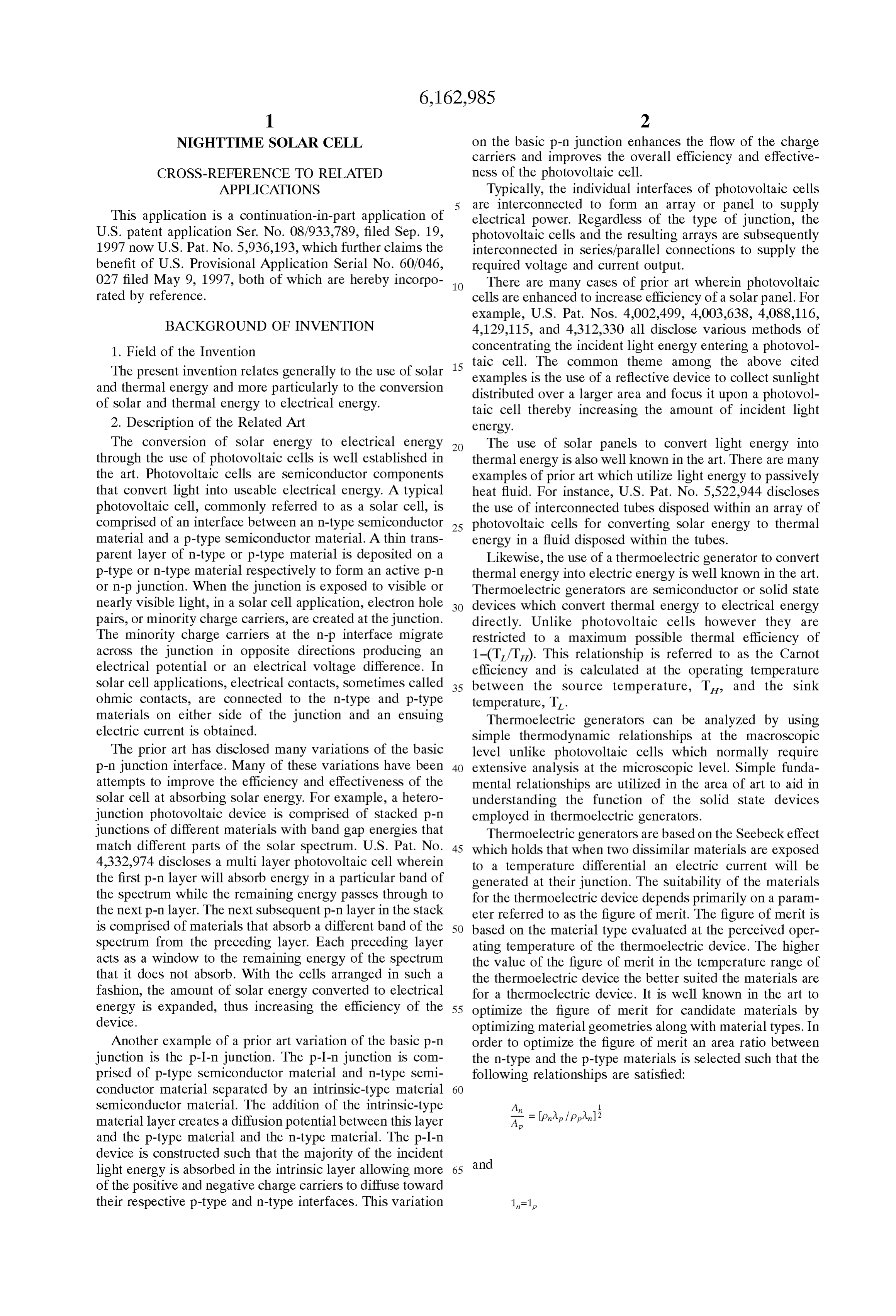
junctions of different materials with band gap energies that Thermoelectric generators are based on the Seebeck effect match different parts of the Solar spectrum. U.S. Pat. No. 45 which holds that when two dissimilar materials are exposed 4,332,974 discloses a multilayer photovoltaic cell wherein to a temperature differential an electric current will be the first p-n layer will absorb energy in a particular band of generated at their junction. The Suitability of the materials the Spectrum while the remaining energy passes through to for the thermoelectric device depends primarily on a param the next p-n layer. The next Subsequent p-n layer in the Stack eter referred to as the figure of merit. The figure of merit is is comprised of materials that absorb a different band of the 50 based on the material type evaluated at the perceived oper Spectrum from the preceding layer. Each preceding layer ating temperature of the thermoelectric device. The higher acts as a window to the remaining energy of the Spectrum the value of the figure of merit in the temperature range of that it does not absorb. With the cells arranged in such a the thermoelectric device the better Suited the materials are fashion, the amount of Solar energy converted to electrical for a thermoelectric device. It is well known in the art to energy is expanded, thus increasing the efficiency of the 55 optimize the figure of merit for candidate materials by device. optimizing material geometries along with material types. In Another example of a prior art variation of the basic p-n order to optimize the figure of merit an area ratio between junction is the p-I-n junction. The p-I-n junction is com the n-type and the p-type materials is Selected Such that the prised of p-type Semiconductor material and n-type Semi following relationships are Satisfied:
conductor material Separated by an intrinsic-type material 60
Semiconductor material. The addition of the intrinsic-type :
material layer creates a diffusion potential between this layer p and the p-type material and the n-type material. The p-I-n device is constructed Such that the majority of the incident and light energy is absorbed in the intrinsic layer allowing more 65 of the positive and negative charge carriers to diffuse toward their respective p-type and n-type interfaces. This variation in p
Page 12
where SUMMARY OF THE INVENTION A area of n-type material The above-discussed and other drawbacks and deficien A area of p-type material cies of the prior art are overcome or alleviated by the energy p, p, electrical resistivity generating device and method of the present invention. The 2, 2, thermal conductivity electricity generating device uses an electricity generating 1, 1, Length of area elements. cell comprising: a first junction Surface disposed in contact With the semiconductor materials selected based on the with a first Semiconductor material; a Second junction Sur above equations, the figure of merit, Z, is optimized by face disposed in contact with a Second Semiconductor mate Satisfying the following relationship: rial; a third junction Surface disposed in contact with the first where Semiconductor material and the Second Semiconductor mate rial; the first and Second junction Surfaces disposed within a (lap + lan)2 preSSure cell having a pressure less than the ambient pres Sure, and the first and Second junction Surfaces at a tem
perature different from the third junction Surface producing a thermoelectric potential between the first and Second junction Surfaces.
C, C, Seebeck coefficients. The method of converting thermal radiation and Sunlight For the optimum figure of merit, Z, the optimum current,
I, produced by the thermoelectric generator is calculated into electrical energy of the present invention, comprising: forming the device by electrically connecting, in a parallel by the following equation:
fashion, at least one thermoelectric cell with at least one photovoltaic cell; orienting the device Such that the thermo lon = (a + 'a, ) (TH - TL) electric cell and the photovoltaic cell are in a perpendicular
arrangement with the Sunlight throughout the orbit; produc 25 ing electrical energy from both the photovoltaic cell and the where thermoelectric cell in the full Sunlight exposure position; and producing energy from the thermoelectric cell in the full
R= p. 1n -- pplp shade position.
An Ap The above-discussed and other features and advantages of the present invention will be appreciated and understood by and those skilled in the art from the following detailed descrip T, T, are the high and low temperatures of the Source and tion and drawings.
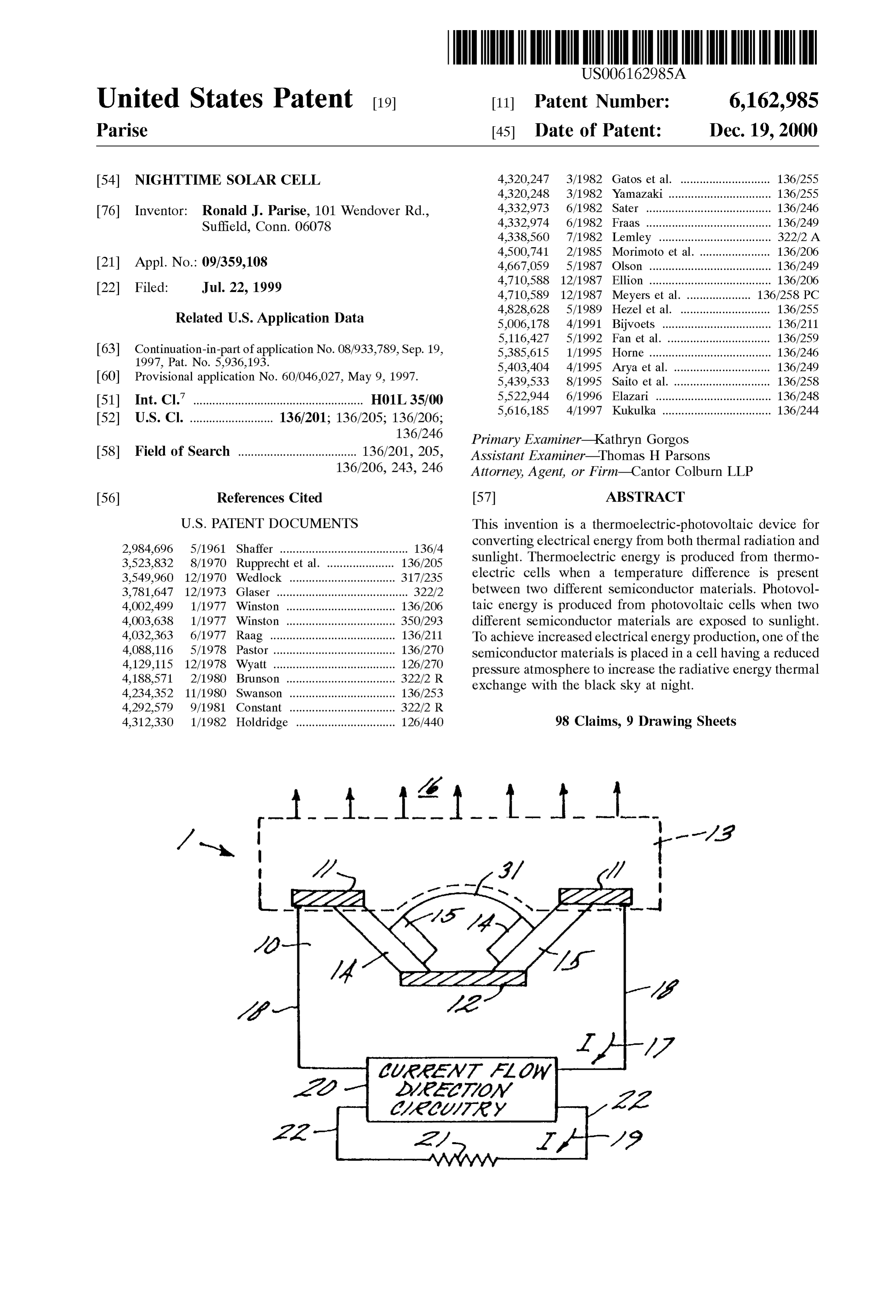
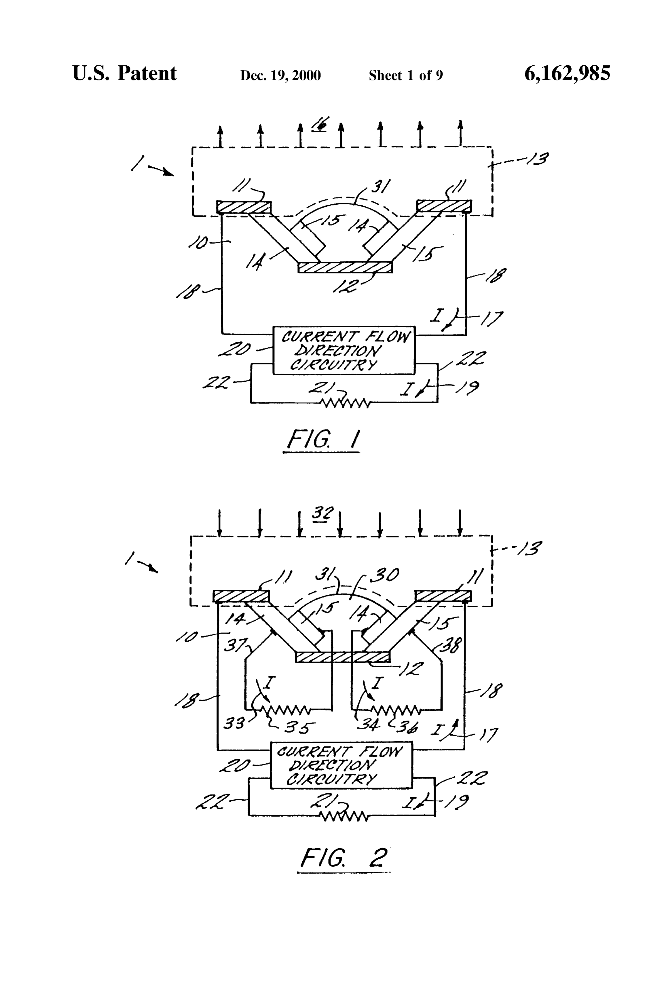
the sink, respectively. BRIEF DESCRIPTION OF THE DRAWINGS and 35 Referring now to the drawings wherein like elements are numbered alike in the Several Figures:
The open circuit Voltage for the thermoelectric generator, FIG. 1 is a Schematic representation of a thermoelectric , is calculated by the following equation: photovoltaic cell of the present invention. FIG. 2 is a Schematic representation of a thermoelectric 40 photovoltaic cell of the present invention.
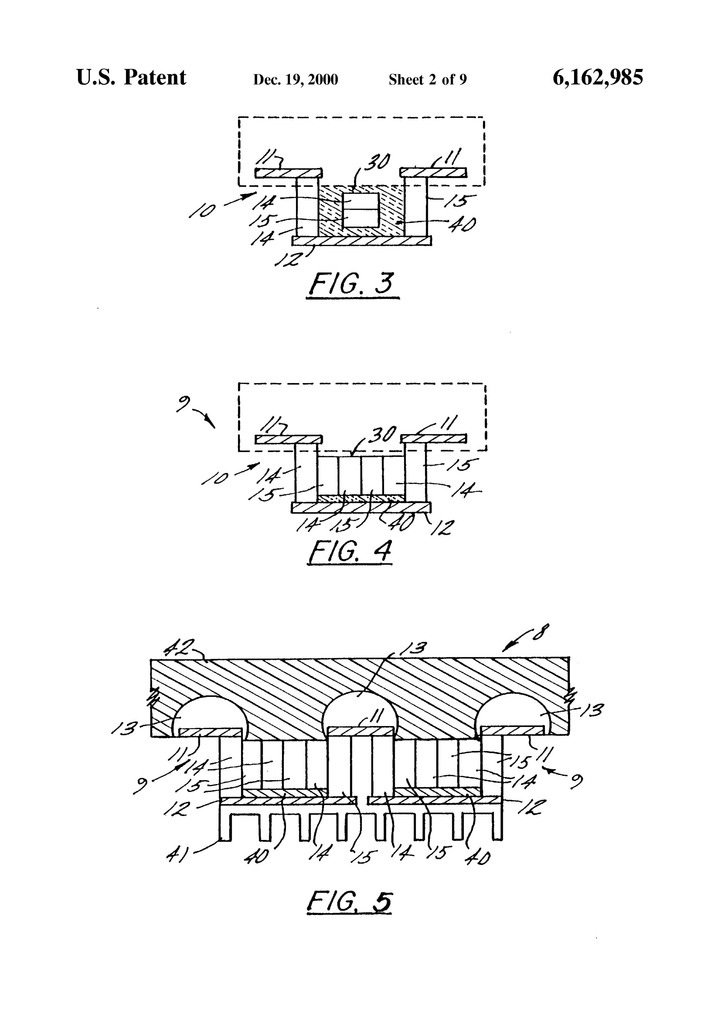
The Specific thermal efficiency of the thermoelectric gen FIG. 3 is a cross sectional view of a thermoelectric erator for the optimized conditions then becomes: photovoltaic cell of the present invention. FIG. 4 is a cross sectional view of a thermoelectric photovoltaic cell of the present invention.
45 FIG. 5 is a croSS Sectional view of an array incorporating a thermoelectric-photovoltaic cell of the present invention.
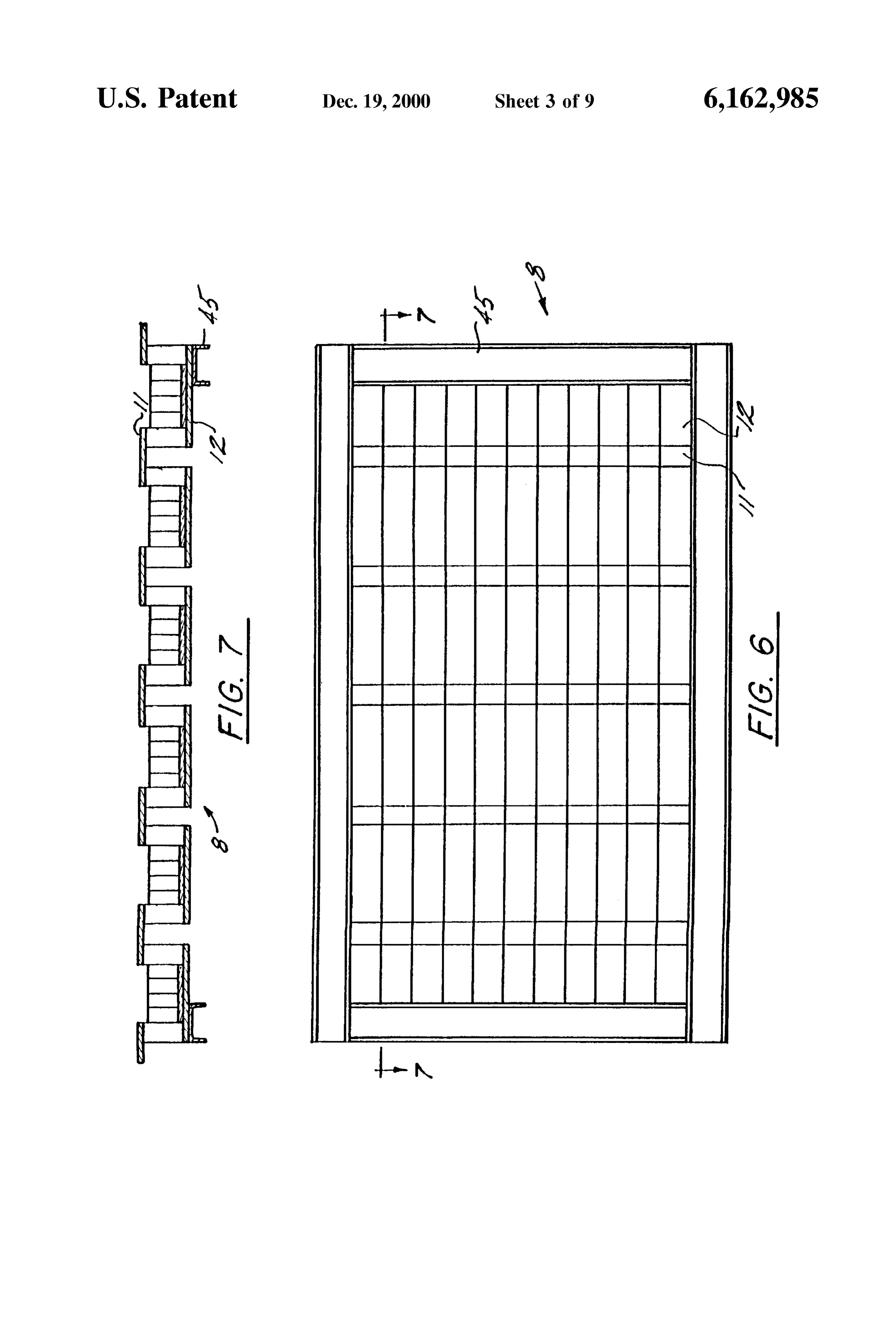
Note that it is not possible for the thermoelectric generator FIG. 6 is a plan View of an array panel and Support to have a thermal efficiency greater than the previously Structure incorporating a thermoelectric-photovoltaic cell of Stated Camot efficiency and as Such T/T at the operating the present invention.
conditions of the device must be less than one. 50
An example of a thermoelectric generator is disclosed in Support FIG. 7 is a croSS Sectional view of an array panel and Structure incorporating a thermoelectric
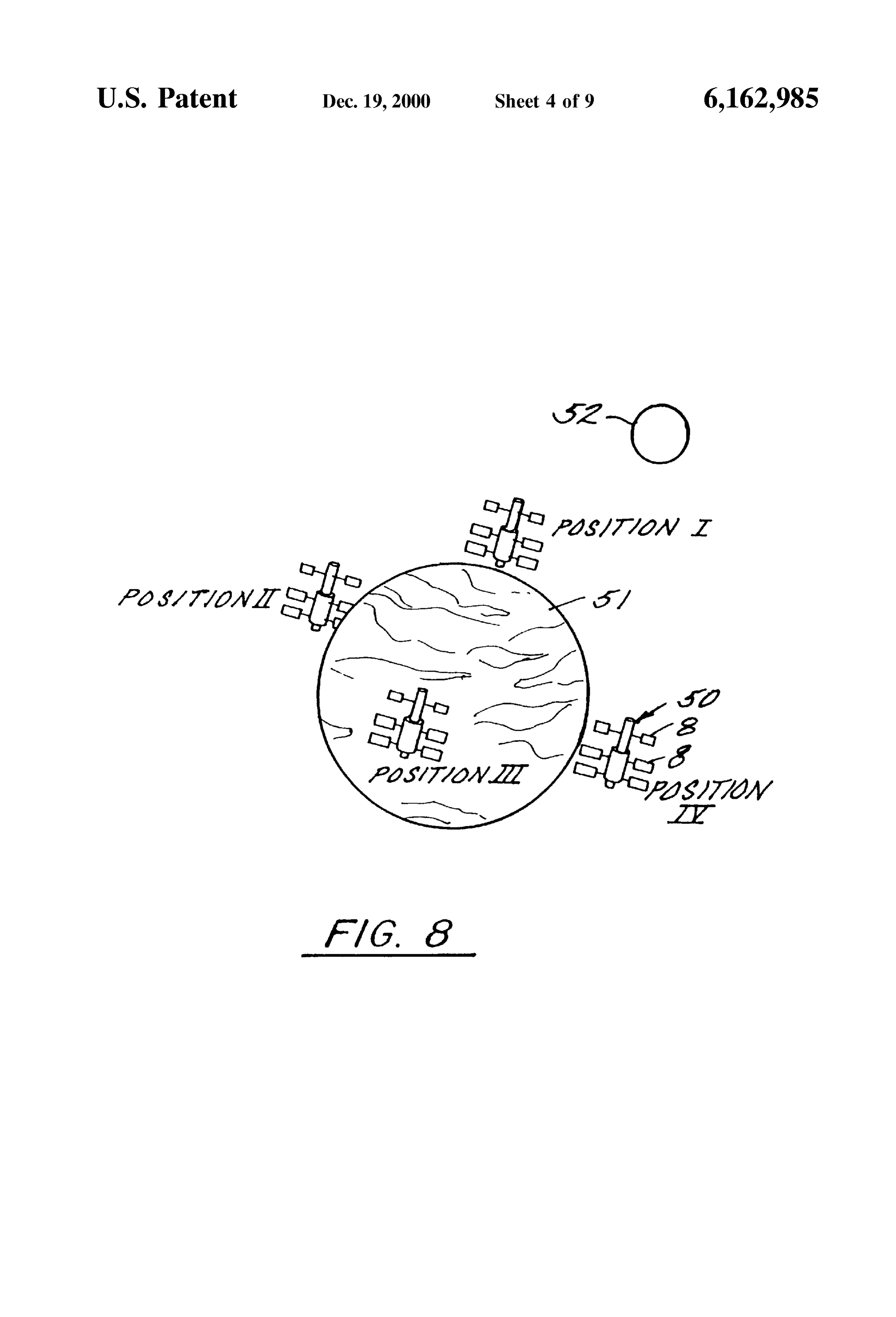
U.S. Pat. No. 4,338,560. The thermoelectric generator of the photovoltaic cell of the present invention. 560 patent discloses a generator that comprises an array of FIG. 8 is a perspective illustration of a satellite incorpo Sources and Sinks interconnected by n-type and p-type doped rating a thermoelectric-photovoltaic cell of the present material elements. It is disclosed that the Sources absorb 55 invention.
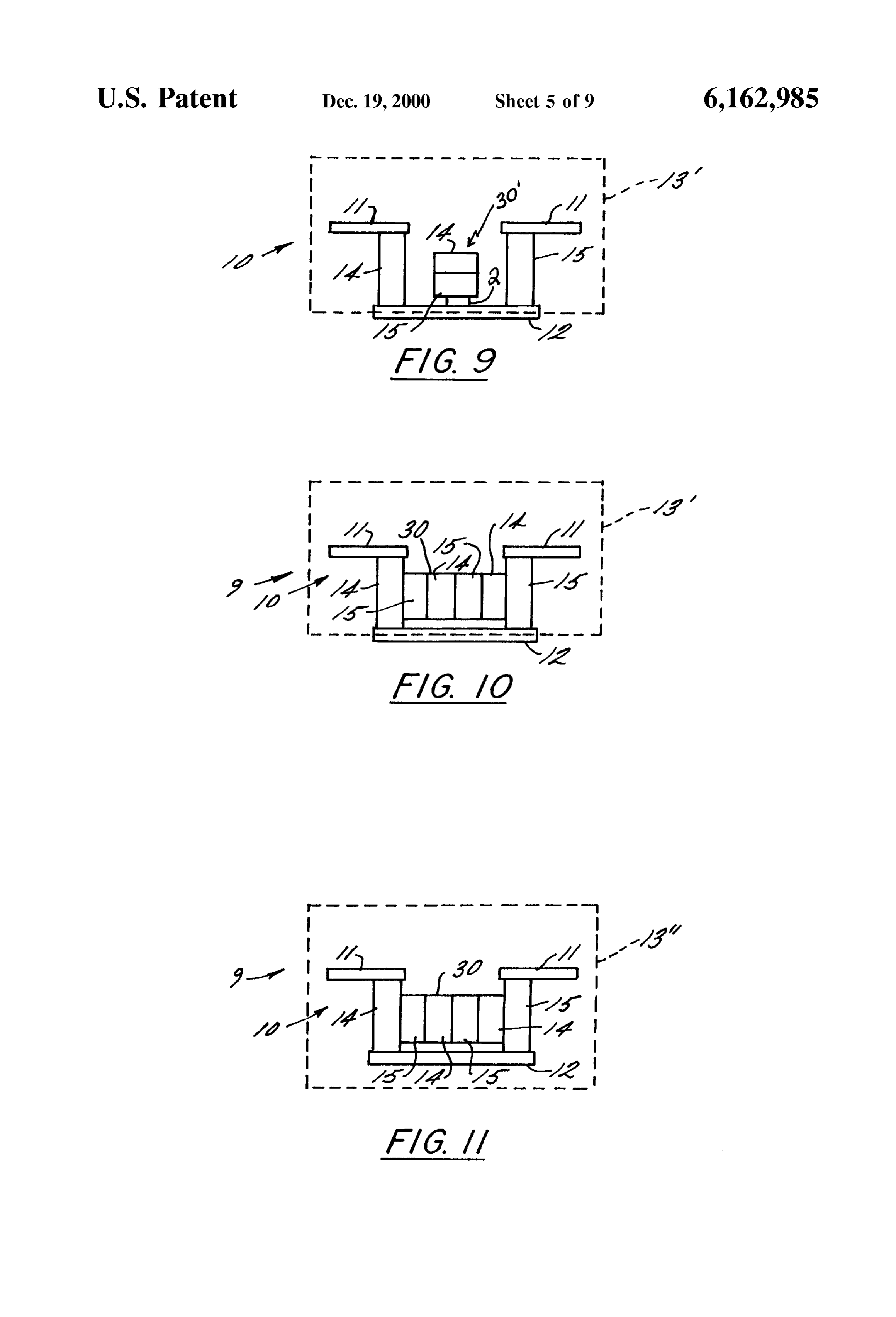
infrared heat from the earth and the SinkS emit exceSS heat to Space. FIG. 9 is a cross sectional view of a thermoelectric State of the art photovoltaic cells work well during photovoltaic cell of the present invention. FIG. 10 is a cross sectional view of a thermoelectric daylight hours or when there is a Sufficient incident light
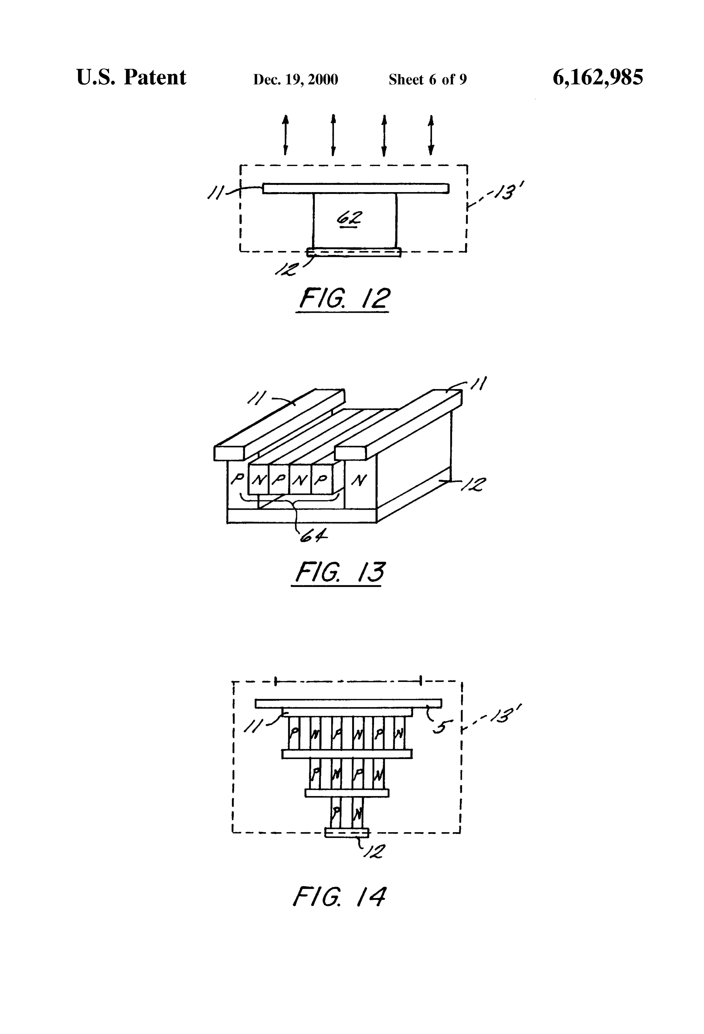
Source, while thermoelectric generators tend to work better 60 photovoltaic cell of the present invention. at night. What is needed is a thermoelectric-photovoltaic cell FIG. 11 is a cross sectional view of a thermoelectric System with both enhanced terrestrial and Space capabilities photovoltaic cell of the present invention. which employs State of the art design and manufacturing FIG. 12 is a cross Sectional view of a thermoelectric techniques to obtain maximum electrical energy output from generator of the present invention where the junction Surface the Solar cells during daylight and Sunlight conditions and 65 area is varied to improve performance. from thermoelectric generator cells from temperature dif FIG. 13 is an isometric view of a thermoelectric ferentials. photovoltaic cell of the present invention where the radiative
Page 13
S 6 area is varied as well as the Size of the various p-type and junction Surfaces produces an electrical current 17 in the n-type materials. p-type material and the n-type material of the thermoelectric FIG. 14 is a croSS Sectional view of a cascading thermo generator.
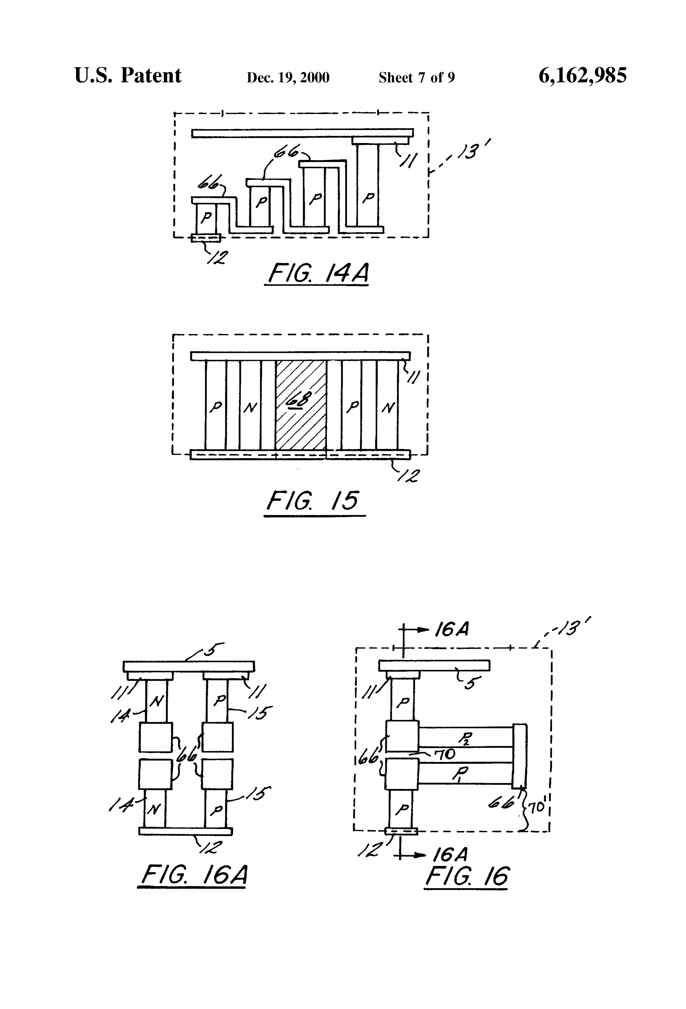
electric generator of the present invention. The present invention utilizes reduced pressure cell 13, FIG. 14A a croSS Sectional view of a cascading thermo 13', 13" (see FIGS. 9, 10, and 11) to take advantage of the electric generator of the present invention. extremely low temperatures of the black sky. The reduced FIG. 15 is a cross sectional view of a thermoelectric preSSure cell can encapsulate the junction Surface 11, encap generator of the present invention where the geometry and Sulate the thermoelectric generator 10 except for junction Size of the p-type and n-type materials are adjusted to Surface 12, or can encapsulate the entire thermoelectric increase thermal resistance and improve power output. generator, to insulate the junction Surface 11 or the thermo FIG. 16 is a cross sectional view of a thermoelectric electric generator 10 from the ambient temperatures. The generator of the present invention which employs metallic preSSure within the reduced pressure cell 13 is a preSSure conductors to enable an increase in the length of the p-type the reducedthepressure lower than ambient preSSure, with the ideal pressure of cell 13 being a perfect vacuum. The and n-type materials. 15 reduced preSSure cell 13 is manufactured from a material FIG. 16A is a cross sectional view of section AA from suitable to allow junction surfaces 11 to “see” the black sky
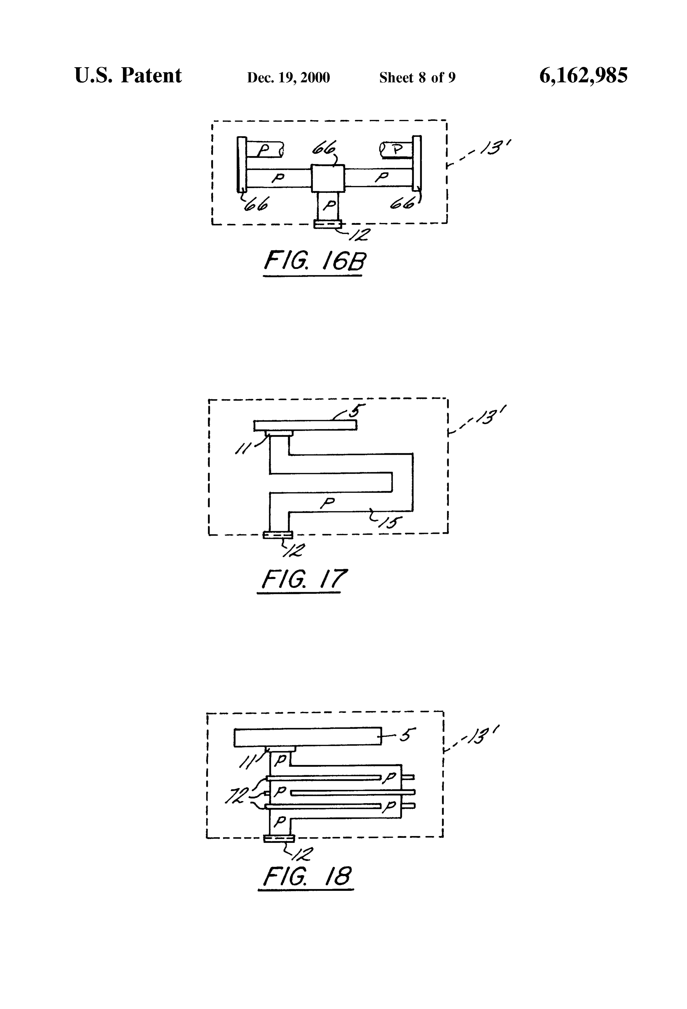
FIG. 16 which illustrates the orientation of the p-type and eXchange energy with it by radiation heat transfer. materials with respect to the n-type materials. In one embodiment, referring to FIGS. 9 and 10, the FIG. 16B a cross sectional view of a thermoelectric generator of the present invention which illustrates another vacuum pressure reduced cell 13' (also known as the vacuum cell or orientation Scheme using a p-type/n-type material arrange majority pod), encapsulates the photovoltaic cell 30 and the of the thermoelectric generator 10, leaving junction ment as in FIG. 16A.
FIG. 17 is a cross sectional view of a thermoelectric
Surface 12 thermally connected to the environment and allowing the establishment of conductive heat transfer with generator of the present invention employing another geom the Surroundings. Utilizing the reduced pressure cell 13' in etry which Snakes the p-type and n-type materials to increase 25 this fashion enables the elimination of the insulation 40 (see their length. FIGS. 3 and 4), thereby reducing the overall system weight FIG. 18 is a cross sectional view of a thermoelectric and cost, while providing a more effective insulation of the generator of the present invention employing thin film photovoltaic cells and allowing the thermoelectric generator insulators to enable condensed Snaking of the p-type and to operate at a higher daytime temperature to improve its n-type materials to optimize usage of Space. performance.
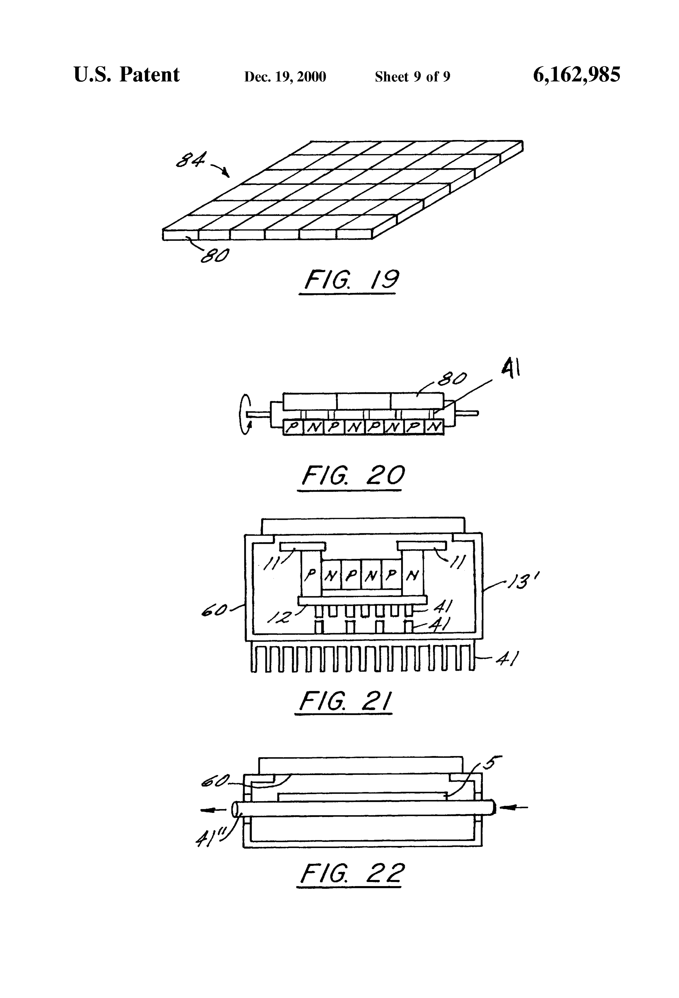
FIG. 19 is an isometric view of an array incorporating In another embodiment, set forth in FIG. 11, the reduced cells of the present invention where the cells are in indi preSSure cell 13" fully encapsulates the thermoelectric gen vidual reduced pressure units arranged in an array. erator 10 and photovoltaic cell 30. In this embodiment, FIG. 20 is a cross sectional view of a thermoelectric 35 junction Surface 12 thermally connects to the environment photovoltaic cell of the present invention which illustrates via radiative heat transfer only. This thermal connectivity daytime and nighttime operation of the cell. enables the amount of heat provided to the thermoelectric FIG. 21 is a cross sectional view of a cell of the present generator 10 during nighttime usage or removed therefrom invention which employs both internal and external heat during daytime usage, to be controlled, particularly in transfer augmentation. 40 extreme temperature conditions. FIG. 22 is a cross sectional view of a cell of the present In FIG. 12, the reduced pressure cell 13' (as shown in invention employing alternate internal heat transfer augmen FIGS. 9 and 10) further comprises an aperture or window 60 tation. (as shown in FIG. 21). This enables the junction surface 11 usage to also serve as a Sink during daytime usage. If the
DETAILED DESCRIPTION OF THE DRAWINGS 45 thermoelectric generator 10 uses the daytime Sky as a sink An embodiment of the nighttime Solar cell of the present (normally shielded from the direct rays of the Sun) then invention is shown schematically in FIG. 1. The nighttime junction Surface 11 is a Sink in daylight usage and junction Solar cell 1 of the present invention includes a thermoelectric Surface 12 is the Source. FIG. 21 further illustrates the generator 10, current flow circuitry 20, and a current load 21. window which forms the aperture 60 of the reduced pressure The generator is comprised of a junction Surface 11, a 50 cell 13' to exchange radiative energy with a radiative Source junction Surface 12, a reduced pressure cell 13, n-type doped or sink. The radiative eXchange area in the cell prefers material 14, and p-type doped material 15. The Schematic line-of-Sight contact with the sink (or Source) energy presented in FIG. 1 depicts the operation of the present eXchange external body only, and hopefully no other bodies invention in a nighttime terrestrial embodiment. The junc that will detrimentally influence the energy exchange. The tion Surface 11 emits thermal energy through radiation heat 55 Size of the aperture can be larger, Smaller, or Substantially transfer 16 to the black sky at night. In this embodiment equivalent to the size of the radiative heat transfer area, with junction Surface 11 becomes a cold temperature Sink for the a size which maximizes the effectiveness of the radiative thermoelectric generator 10 preferably having an emissivity heat transfer area preferred.
greater than 0.90, with about 0.96 to about 0.99 especially To improve the radiative characteristics of the energy preferred. The black sky has an effective temperature around 60 eXchange, Spectral transmitting characteristics of the win Zero degrees absolute temperature which allows the cold dow with the external body can be chosen accordingly. For temperature Sink to radiate heat to the black Sky via elec example, when deep Space is used as a sink, deep Space at tromagnetic energy. In a terrestrial embodiment of the approximately 4 K is always visible to terrestrial objects in present invention the junction Surface 12 is the hot tempera certain band widths. Rain, Snow, clouds, etc., ture Source as it is exposed to ambient temperature, typically 65 notwithstanding, there is always an energy exchange. Win about 200 K to 325 K, with about 220 K to 310 K more dow optical properties will be Selected to optimize this common. The temperature difference that exists between the energy exchange. Coatings may also be applied to the
Page 14
window to augment or improve its energy transmitting 32 enters the device and warms junction surfaces 11. The capabilities. The internal surface of the window can be irradiation of Solar energy upon junction Surface 11 causes coated to maximize transmission from the radiative heat the junction Surfaces to become the hot junction and the transfer area while minimizing the internal reflectivity. Also, relatively cooler ambient conditions cause junction Surface when exclusively using thermoelectric generators and deep 12 to become the cool junction Surface for the thermoelectric Space as a sink, the external window Surface may be coated generator. In a preferred embodiment, the absorptivity of with coatings that affect maximum reflectivity of all energy, surface junction 11 is greater than 0.90. In addition, for with minimum transmission inward. certain embodiments it is advantageous to Select a material Alternatively, if the daytime usage will be exclusively for surface junction 11 wherein the emissivity and the absorptivity are nearly equal. Electrical current 17 is gen thermoelectric generator elements that utilize the Sun as a erated by the temperature difference between the hot and thermal Source, then maximum transmissivity is desired cold junction Surfaces and is opposite in direction to that through the external Surface of the window. The optical produced during nighttime operation. Current 17 is carried properties of the window and the Surface coatings would to current flow direction circuitry 20 wherein its direction is preferably effect this result, with radiative energy band properly oriented into outgoing current 19 and carried to widths maximized. 15 load 21 via connection 22 where it is either stored or In an alternative embodiment employing the thermoelec consumed.
tric generators and the photovoltaic cells in parallel arrange Alternatively the thermoelectric generator could be Solely ment exposed to the external Surroundings of the window, utilized, even during the day. In this operating mode, during the coatings which maximize the transmissivity of the the day, the thermoelectric generator would be shielded from energy needed to heat the hot junction of the thermoelectric the rays of the Sun and allowed to look at deep Space. This generator elements is preferred. These coatings should also mode of operation is the same as the nighttime mode of allow the transmittance of the Solar radiation that eXcites the operation, and the current flow direction Sensing circuitry is electrons in the photovoltaic cells into the conduction band not necessary, but the reduced pressure cell is preferred for improved operation.
to increase electron activity and improve electrical power 25 generation. Yet another mode of operation would be to expose the radiative heat
It should be noted that if the daytime usage will be that it becomes the hot transfer area to the direct rays of the Sun So exclusively employing thermoelectric generator units which generators junction for the thermoelectric will utilize the Sun as a thermal Source, then maximum and the ambient environment (or Some other transmissivity in the Solar thermal range (blocking deep sink) becomes the Sink temperature for the waste heat. This mode of operation is opposite to the nighttime mode, there
Space coating) is desired through the external Surface of the fore the current flow direction circuitry is employed. window into the pod. The optical properties of the window Although the connections and loads illustrated in FIGS. 1 and the Surface coatings would effect this result, with and 2 are shown as separate they may be combined and appropriate radiative energy bandwidths maximized. interconnected with other Such devices as the electrical The appropriate coating to be applied to the interior 35 needs of a particular embodiment dictate. The embodiment and/or exterior Surface of the window can readily be deter shown in FIGS. 1 and 2 may be terrestrial or space based. mined by an artisan, with coatings which would allow The important distinguishing characteristic between a ter transmissivity for the atmosphere of about 8 um to about 13 restrial based application and a Space application is the tim, preferred. reduced pressure cell. The reduced pressure cell insulates the The electric circuit of an embodiment of the nighttime 40 Surface junction of the thermoelectric generator from the Solar cell is also shown in FIG. 1. During nighttime periods, earth's ambient Surroundings while Simultaneously allowing or periods without incident light, current 17 travels in the for the Surface junction to react radiatively with the Sun or direction shown from junction surface 11 to current flow the night Sky. In Space based applications the insulative direction circuitry 20 via connection 18. Current flow direc properties of the reduced pressure cell are not necessary. tion circuitry determines the direction of the incoming 45 Referring now to FIG. 3 there is illustrated another current 17, and properly orients the current into outgoing embodiment of the present invention. This embodiment is current 19 which is carried via connection 22 where it is configured for terrestrial use and includes, in addition to the stored or consumed by load 21. embodiments previously described, thermally insulative Referring next to FIG. 2, there is illustrated a schematic material 40. Thermally insulative material 40 insulates pho representation of an embodiment of the present invention 50 tovoltaic cell 30 from thermoelectric generator 10. With the during daylight operation. In addition to the embodiment two devices thermally insulated the performance of the previously described the nighttime Solar cell illustrated thermoelectric generator is not influenced by any thermal includes a photovoltaic cell 30 comprising concentrating transfer from the photovoltaic cell, and the overall perfor lens 31, n-type doped material 14, and p-type doped material mance of the nighttime Solar cell is enhanced. In addition the 15. Photovoltaic cell 30 is arranged within thermoelectric 55 photovoltaic cell is not influenced by the thermoelectric generator 10. During daylight operation an embodiment of generator. The embodiment shown in FIG. 3 may also the present invention produces electrical energy from ther advantageously include a concentrating lens as previously moelectric generator 10 as well as photovoltaic cell 30. described.
Concentrating lens 31 receives Solar energy 32 falling Referring next to FIG. 4 there is illustrated another between junction Surfaces 11 and focuses it upon n-type 60 embodiment of the present invention. In the embodiment doped material 14 and p-type doped material 15. Thus illustrated the photovoltaic cell 30 includes n-type 14 and configured photovoltaic cell 30 generates current 33, 34 p-type 15 materials connected in Series with n-type 14 and which is carried to load 35, 36 via connections 37, 38. p-type 15 materials of the thermoelectric generator 10 to The operation of a thermoelectric generator during day yield a series thermoelectric-photovoltaic device 9. In this light conditions is also illustrated in FIG. 2. During daylight 65 particular embodiment the charge carrier collection conditions thermoelectric generator 10 functions opposite to capability, or the current flow, of the device is greatly that described above for nighttime conditions. Solar energy improved.
Page 15
Illustrated in FIG. 5 is still other embodiment of the The use of the cascading arrangement increases the length present invention. The partial array 8 illustrated includes a of the thermoelectric generator elements and the thermal pair of Series thermoelectric-photovoltaic devices, heat resistance of the module, thereby allowing increased power transfer fins 41, and encapsulant 42. Heat transfer fins 41 are output. The performance of the thermoelectric generator is disposed in heat eXchange relationship with junction Sur dependant on the temperature differential across the module. faces 12 and the ambient air. During nighttime operation the By increasing the length of the module p-n materials, the heat transfer fins enhance the conduction of heat from the temperature differential increases. This length increase can ambient air to the junction Surfaces, and during daylight be used to optimize (maximize) the power output from the conditions the heat transfer fins improve the transfer of heat unit. Increasing the length of the p-n material can result from from the junction Surfaces to the ambient air. Various heat unique cascading designs as shown in various embodiments transfer augmentation can be utilized Such as forced air, of this patent. Numerous other geometries can also be used water, another fluid, or a thermal Source of waste heat for to increase the thermal resistance of the p-type and n-type nighttime operation (e.g., a fluid heat exchanger, baffled heat materials, including a coiled or curved geometry; a long, exchanger, radiation shield, heat transfer composition) and Slender geometry, unique cascading, element Snaking, and forced air, water, another fluid, or a thermal Sink for daytime 15 element Stacking geometry, among others and combinations operation, among others, and combinations thereof. thereof, as well as various p-type and n-type material Furthermore, the heat transfer augmentation can be disposed orientations, including, but not limited to, parallel, on junction Surface 11 and/or 12, external to the cell, or perpendicular, 30, 45, 60,90, 180°, or some other angle. internal to the cell, i.e. in thermal communication with the For example, FIG. 15 illustrates long, slender p-type 15 reduced pressure cell 13, 13", 13", junction surface 11, and/or and n-type 14 materials used in conjunction with a mechani junction Surface 12. Furthermore, the heat transfer augmen cal Support 68 for providing Structural integrity to the tation can be used for units that are ganged or assembled in materials 14, 15, wherein the ratio of the length of the p-type arrays or on panels and includes the use of a forced fluid in 15 and n-type 14 materials to the area thereof is preferably a conduit or pipe (e.g., see 41" as shown on FIG. 22) about 4 or greater, with about 5 or greater especially thermally attached to the pod, or of a waste Stream that could 25 preferred. The mechanical Support 68 employed herein, add or remove energy from the units as required. Encapsu which can be a Single or multiple Sectioned Support and lant 42, essentially a cover, is bonded to junction Surfaces 11 which is preferably additionally a thermal and electrical under reduced preSSure conditions to form reduced pressure insulator, enables Static Support of the junction Surfaces 11, cells 13. 12, as well as for dynamic applications of the reduced Further embodiments of the present invention are illus preSSure vessel, and improved Structural integrity of the trated in FIGS. 12-18 which illustrate some of the possible p-type 15 and n-type 14 materials. Possible mechanical variations, both relative size and geometry, of the thermal Supports 68 can be composed of a thermally insulating junctions 11, 12 and/or the p-type 15 and n-type 14 mate material capable of maintaining the distance between the rials. In FIG. 12, junction Surface 11 has a larger Surface area junction Surfaces 11, 12. The Size and geometry of the than junction Surface 12, with a thermoelectric generator 62 35 mechanical support 68 should be sufficient to provide the disposed therebetween accordingly. FIG. 13, which does not necessary Structural integrity to the p-type 15 and n-type 14 show the reduced pressure cell for clarity, illustrates a materials.
thermoelectric generator coupled with a photovoltaic cell 64 FIG. 16 illustrates that the length of the p-n elements can in a parallel fashion. The junction Surface 11 extends over be extended significantly when put into the reduced preSSure the n-type and p-type material with the radiative area for the 40 vessel. In this embodiment, the thermal conductors 66, thermoelectric generator greater than the area for the pho which are typically composed of a metallic or Semiconduc tovoltaic cell 64. This embodiment allows for parallel power tor material, are transition pieces which allow the Semicon generation using both the thermoelectric generator and pho ductor materials to be installed in a perpendicular orientation tovoltaic cell, allowing for higher daytime temperature (or Some other angle) to the original p-n material. In this operation of the thermoelectric generator without detrimen 45 way, Several "layers' of p-n material can be added without tally impacting the operation of the photovoltaic cell. increasing the distance between the hot and cold junctions of Referring to FIGS. 14 and 14A, which illustrates a the module, while at the same time increasing the thermal cascaded thermoelectric generator with the larger junction resistance of the module. Since the temperature differences Surface 11 exposed to the radiative aperture 60, and an between the different material Sections are Small enough and additional, optional radiation heat transfer area 5. The radia 50 due to the employment of the reduced pressure vessel, the tion heat transfer area 5 which is another heat transfer plate mode of heat transfer, radiation, between the material Sec Similar to and thermal conductively connected to junction tions is rendered insignificant. Consequently, Such an Surface 11, can be sized to increase or decrease the amount arrangement of p-n materials is possible without adversely of energy radiated external to the cell to improve the overall effecting the power output of the System. operation of the electric power generator; e.g. it can be as 55 Furthermore, Since matching the temperature differential Small as the Surface area of the Small junction Surface or as to the operating range of the p-type and n-type material large as the aperture opening to provide the greatest flex improves output of the p-n junction, as is shown in FIG. 16 ibility of area variation to control the energy that the module (p and p), the p-type and n-type materials can be selected can exchange radiatively through the aperture 60. Sizing of for the different “legs” of the layers that operate in a the radiation heat transfer area can be a ratio (larger or 60 temperature range that is best Suited for the temperature Smaller) than the cross-sectional area of the Sum of the differential which that particular material will experience in thermoelectric generator elements in a Single tier or of the that portion of the unit.
other Surface area exposed thermally to the exterior of the It should be noted that the increased thermal resistance reduced pressure cell. AS with the junction Surface, the provided by a design Such as in FIG. 16, can eliminate, for radiative heat transfer area can be a thermally conductive 65 certain applications, the need for the reduced pressure cell. material including metals. Such as copper, aluminum, com Although the vacuum pod or cell provides the ideal envi binations thereof and others. ronment for insulation between the Stacked or layered p-n
Page 16
materials, under certain conditions the layered module can versa) Such that the thermal resistance is entailed throughout operate without the benefit of the vacuum. For example, in the entire Semiconductor material. The added material can a system operating in the 400 K to 600 K temperature be utilized to increase the electrical power output of the range, although not limited to this range, atmospheric air (or module. Mechanical Support of the Snaked legs of the p-n Some other gas) could provide adequate insulation between 5 the material can be added to improve the Structural integrity of layers. Radiative heat transfer effects would be negligible in module.
this low temperature range and the System would function Optionally, the p-n element could be drawn through a wire well. Air circulation through the module would also improve die (or by Some other means) to manufacture the thermo performance. Even a mechanical insulation could be pro electric generator elements as a long thin wire. Coating the Vided to ensure heat transfer through the p-n materials and wire with insulation, then coiling the element into a Small not between the material Stacks. In certain applications the mass to fit into the vacuum pod would improve both thermal Vacuum cell may not be rugged enough to maintain the and electrical properties and characteristics of the module. vacuum. Therefore, this particular embodiment of the In FIG. 18, the p-type and n-type materials reside on thin present patent applies. film insulators 72 which enable the construction of light FIG.16 also shows an embodiment of the invention where 15 weight modules. In this embodiment, thin film technology is Surface 5 can be connected thermally to the Surroundings by employed to manufacture the p-type and n-type materials by conduction heat transfer, eliminating the need for a window the deposition of the Semiconductor on thin film insulators or aperture. Again this is one of the many configurations that can be installed into the reduced pressure cell. This allowed by the flexibility of the present invention. enables further Snaking the p-n elements, laterally, longitu FIG. 16A illustrates one simple scheme of how the p-type dinally and otherwise, to increase the thermal resistance of 15 and n-type 14 materials can be oriented with respect to the System and improve the cross-sectional area of the Semiconductor material, hence improving the power gener one-another and the thermal conductors 66. Meanwhile, ating capabilities of the vacuum pod. Various types of thin FIG. 16B illustrates another orientation scheme using the film insulators can be employed, Such as those having reduced pressure vessel 13' where the length of the p-type 15 25 Sufficient thermal insulation to inhibit adverse thermal and n-type 14 materials can be extended significantly using effects between the elements. Possible insulators include thermal conductors 66 to transition the materials. Numerous glass, ceramic, thermoplastics, and thermoset materials, other orientations can be envisioned and are within the Scope among others, combinations and composites thereof. The of the present invention. For example, in FIG.16B the initial thickness of these films should be Sufficient to attain the Vertical p-type material up to the thermal conductor 66 could desired insulating effects, with a thickness up to about 30 have a cross-sectional area twice that of the two perpen mils or greater typically sufficient, below about 20 mils dicular p-type materials to maintain balanced thermal and preferred, and up to about 10 mils especially preferred. electrical energy flows. Furthermore, as with other of these FIG. 19 shows individual reduced pressure units 80 designs, Several “layers of p-type and n-type material can ganged be added to form an array. It should be noted that in addition 35 capabilityintoofanthearray 84 to improve the power producing units and produce the electrical output to the thermal conductors 66, insulators can also be employed, Such as in area 70, to improve mechanical characteristics desired. These units can be designed to have Side-by-side plug-in assemblies with Series or parallel elec integrity.
trical connections as well as end-to-end plug-in assemblies,
In addition to geometry alternatives, the metallic conduc e.g. similar to Lego TM or Erector SetTM modules with plug-in tors increase the thermal resistance, providing a greater 40 capabilities. The vacuum pods could also have electrical temperature differential for the module to operate in, thereby connections that come out of the bottom to assemble the increasing the power output. Consequently, the metallic modules on a buSS or can be manufactured as a gang of units conductors should be capable of increasing thermal resis that are connected electrically and evacuated as a single unit tance without adversely affecting the electrical properties at but Sealed as individual cells. Again, there is no restriction the electrical connections between the p-n material and the 45 on the size of the vacuum pod or the number of modules metallic conductors. Possible metallic conductors include inside. Consequently, various units can be connected elec copper, gold, aluminum, and Silver, among others. trically to produce a desired Voltage and current as required Embodiments employing metallic conductors are illus for the application of the power generating unit. In practice, trated in FIGS. 14A, 16, 16A, and 16B. In FIG. 14A, which to ensure that a majority of the vacuum pods maintain their is a variation of the cascading illustrated in FIG. 14, thermal 50 Vacuum, hence their maximum power producing capability, conductors 66 connect similar materials (e.g. p-type Smaller pods, interconnected electrically but isolated materials). mechanically (i.e., Small chambers), are desirable. Therefore Design of the thermoelectric generator focuses upon the unit shown in FIG. 19 can have individual chambers for obtaining a stable, maximum temperature differential in the Vacuum purposes but be interconnected electrically. Obvi operating range of the thermoelectric generator. Factors 55 ously the vacuum chamber can be as large as desired. effecting the design of the module include the thermal FIG. 20 demonstrates an embodiment of the present conductivity and geometric Specifications of cross-sectional invention as part of an assembly to increase the power area, and length of the p-type and n-type material elements. producing capability of an area dedicated to producing The geometry, in conjunction with the thermal conductivity, power from a renewable Source. Daytime utilization of the influence the thermal resistance of each element, which, in 60 area produces electrical energy from a Solar panel, with or turn, determines the temperature differential between the hot without thermoelectric generators as part of the energy and cold junctions. producing medium. For nighttime utilization of the area, the Alternatively, as is illustrated in FIG. 17, the semicon panel is rotated to expose the opposite Side of the panel to ductor material (p-type material) can be a continuous the nighttime sky and produce electrical energy from the medium without metallic conductors to interrupt the per 65 Vacuum pods with thermoelectric generators. In this way, pendicular transition. Here the p-n materials “snake” the full more of the available energy producing area can use the distance from the hot junction to the cold junction (or vice thermoelectric generatorS eXclusively at night when the
Page 17
photovoltaic cells are ineffective. There are many Schemes Embodiments of the inventions do include other configura that can be incorporated in combining the cells back-to-back tions including cascading or staging of the materials to in this mode to allow the circulation of air, water, or other improve the efficiency. In addition, the particular type of fluids of thermal capability (cooling or heating) to augment material for various embodiments includes those known in and enhance the power producing capability of the panel. the art as well as those yet to be developed. For example, Referring next to FIGS. 6 and 7 there is illustrated an most photovoltaic cells in use today employ monocrystalline array of the thermoelectric-photovoltaic device of the and polycrystalline Silicon. However, more expensive com present invention. In this embodiment there are included pound SemiconductorS Such as GaAS, InP, and CdTe as well support rails 45 fixedly attached to array 8. This embodiment as various ternary and quaternary compounds Such as is particularly Suited for electrical power generation in AlGaAs or GaAs.InP have shown promise for photovoltaic connection with a device in a low-earth orbit. With the cell applications. With respect to materials for the manufac Support rail disposed as illustrated the array would be ture of thermoelectric generators materials. Such as BiTes, oriented such that surface junction 12 would be the hot PbTe, or PbSnTe, among others and mixtures and alloys junction and junction Surface 11 would be the cold junction. thereof, are quite Suitable.
Because the ambient atmosphere of Space has a reduced 15 The thermoelectric-photovoltaic units of the present atmosphere, this embodiment would not require the reduced invention can employ a reduced pressure cell around part or preSSure cell. A similar Support Structure could be envi the entire thermoelectric-photovoltaic unit. The reduced Sioned for mounting the array from the opposite Side. preSSure cell insulates the cold junction from the ambient Referring finally to FIG. 8 there is illustrated a satellite 50 temperature, providing excellent insulation of the cold junc employing an embodiment of the present invention. Satellite tion from the Surroundings, while at the same time, allowing 50 is illustrated in a low orbit about earth 51 including panel the cold junction to "see’ the black sky and exchange energy arrays 8 positioned about its exterior. The array panels are with it by radiation heat transfer. Similarly, during daytime oriented Such that there is always a hot side of the array and operation of the System, the reduced pressure cell insulates a cold Side of the array. For example at position I as depicted the hot junction of the module, now heated by the Sun, from in FIG. 8 the hot side of the thermoelectric generator and the 25 the cool ambient air, improving the power generating capa photovoltaic cells are facing the Sun 52. In position I the bility of the module.
thermoelectric-photovoltaic array is producing electrical The present invention further improves the performance energy to power the Satellite from both the thermoelectric (increases the electrical power output) of the unit by adjust generator as well as the photovoltaic cells. In positions II ing the geometry and/or Size of the p-type and n-type and IV a portion of arrays 8 are shadowed by the earth and materials to increase their thermal conductive resistivity. For a portion are in direct Sunlight. In these positions the example, the materials of the present invention have a photovoltaic cells in Sunlight are producing energy while the preferred length to cross-sectional area ratio of about 4 or photovoltaic cells in the shadow of the earth are not. At the greater, with about 5 or greater especially preferred. At these Same time the thermoelectric generators in Sunlight are ratios, it may be preferable to employ Support to improve producing energy by absorbing Solar radiation and emitting 35 Structural integrity of the materials. Consequently, Supports heat to the ambient atmosphere while the thermoelectric can be employed, Such as disposing insulation columns generators in the Shadow of the earth are absorbing heat parallel to the individual thermoelectric elements to improve from the ambient atmosphere and emitting heat to black sky. rigidity and cell durability, while not providing a thermal In position III all of the arrays are in the shadow of the earth link between the two junctions.
while the backside of the arrays are facing deep Space. In this 40 Performance improvement is also realized. In one pre position the photovoltaic cells are not functioning to produce ferred embodiment, various configurations of thermoelectric energy. The thermoelectric generators are producing elec generator cascading can be utilized to improve overall cell trical energy by absorbing heat from the ambient atmosphere performance when compared to a single row of elements and emitting heat to deep Space. which has no cascading. The thermoelectric generator cas The thermoelectric-photovoltaic device of the present 45 cading then provides the element area ratio with the radia invention Solves many of the problems of the prior art. In a tive area that includes a factor or constant that improves the terrestrial Setting during nighttime conditions the reduced thermal resistance. Increasing the thermal resistance of the preSSure cells Surrounding the cold junction Surfaces of the p-n materials increases the temperature differential between thermoelectric generator enhance the heat transfer relation the hot and cold junctions of the thermoelectric generators, ship between the device and the black Sky thereby increasing 50 improving the thermoelectric generator's power producing the effectiveness of the device and utilizing the Surface area capability. This can also be accomplished utilizing unique of the device to produce energy at night. During daylight cascading Schemes that increase the length of the p-n terrestrial operation the device combines photovoltaic cells elements. Alternatively, lengthening the thermal path can be with thermoelectric generator cells in a Staged fashion Such accomplished by introducing horizontal (or Some other that the full Surface area of the cell is exposed to Sunlight and 55 angle) flow paths of the thermoelectric generator elements thermal energy to produce electrical energy. By contrast with offset hot and cold plates. The elements can be snaked U.S. Pat. No. 4,710,588 discloses a Solar cell in combination up and down or back and forth for a Series of convolutions with a thermoelectric generator in a Series fashion. Because to increase the thermal resistance between the hot and cold of the Series arrangement of the elements the thermoelectric junctions of any pair. If the increased length takes place in generator cannot effectively absorb thermal energy from the 60 the horizontal direction, many more embodiments of the Sun during daylight conditions and cannot effectively emit patent can be envisioned. It should be noted that increased heat to black Sky at night. In addition, the basic design of the thermal path, while increasing the temperature differential, current invention takes advantage of current State of the art does affect electrical performance of the module. By con manufacturing techniques using thin film and/or transparent trolling the thermal path, however, more options are avail electrical connectors with thin film Semiconductor materials. 65 able for geometric design to improve electrical output. The embodiments of the present invention set forth fea AS has been previously Stated, performance of a thermo ture basic p-type material and n-type material junctions. electric generator is a function of temperature differential
Page 18
and the stability thereof. The present invention employs The energy generating device of the present invention Stable thermal SinkS and Sources, for example, the black Sky teaches: (1) using the reduced pressure cell to improve and the Surrounding air, with other Sources and SinkS pos thermal insulation between the thermoelectric generators sible. With respect to the temperature differential, a maxi and the photovoltaic cells as well as between the various p-n mum temperature differential in the operating range of the elements of the thermoelectric generators and their hot and p-type and n-type materials is preferred. The units are cold junctions as well as the p-n elements with the Surround designed to enable a controlled temperature drop which will ings and/or the ambient; (2) the area ratios between the hot determine the temperature differential. and cold junction plates as well as the thermoelectric gen A further advantage of the present invention is that the erator element areas can be augmented to improve System unit is capable of radiating thermal energy from any Standard performance; (3) various cascading Schemes and module thermodynamic cycle into deep Space, thus “dumping” designs (including lengthening of the thermoelectric gen waste energy away from the environment of the earth into erator elements) to improve temperature differentials outer space. For example, in a large power plant that between the hot and cold junctions, improving the power operates on the Rankine Cycle, there is a large amount of producing capability of the vacuum pods; (4) improved waste thermal energy that enters the environment. This is 15 overall Strength between the hot and cold junction Support Such a large amount of energy (on the order of 100's of plates, allowing for thinner, longer p-n elements; (5) per kilowatts) that the pod array may be too large to be practical. pendicular or parallel (or any other angle) p-n elements with But in rural applications where Stirling cycle engines can added length to improve power generating capabilities; (6) pump water for domestic use or irrigation, the vacuum pod manufacturing the configuration of the p-n elements in a may be usable. The vacuum pod could lower the overall fashion that allows “Snaking” of the elements to increase operating temperature of the unit and/or improve cycle temperature differentials; (7) using thin film and thin film efficiency. This embodiment of the present invention is Semiconductor materials, for the thermoelectric generator's shown in FIG. 22. capability of increased temperature differential operation; Yet another advantage relates to the parallel operation of (8) the combination of a power panel with the vacuum pod the device. Increased operating temperature of the photo array construction back-to-back with a photovoltaic cell Voltaic cell reduces the performance, hence the power pro 25 array will increase Significantly the electrical power output ducing capability, of the device. In the Series operation of the of a given panel area, tremendously improving the State of prior art device, the photovoltaic cell must become very hot the art of electrical energy production possible from a given for the thermoelectric generator to perform adequately. The area; (9) the improved spectral properties of the aperture higher the operating temperature differential of the thermo window to enhance the operation of the vacuum pod. electric generator, the better the performance. However, this While preferred embodiments have been shown and high operating temperature is detrimental to the performance described, various modifications and Substitutions may be of the photovoltaic cell. To prevent the photovoltaic cell made thereto without departing from the Spirit and Scope of from becoming too warm, the operating temperature of the the invention. Accordingly, it is to be understood that the thermoelectric generator must be reduced, to maintain good present invention has been described by way of illustration performance of the photovoltaic cell, therefore, there are two 35 andWhat not limitation.
is claimed is:
opposing physical phenomena that must be balanced to try to operate the device. In the present invention, these two 1. An electricity generating device for use in an environ physical phenomena can be optimized for maximum per ment having an ambient pressure, using an electricity gen formance of the photovoltaic cell as well as the thermoelec erating cell comprising:
tric generator. Referring to FIG. 9, for example, the P-N 40 a first junction Surface disposed in contact with a first element in the center of the device is the photovoltaic cell 30' Semiconductor material;
which is thermally insulated from the Surrounding thermo a Second junction Surface disposed in contact with a electric generator. Therefore, in this embodiment, the pho Second Semiconductor material; tovoltaic cell 30' and the thermoelectric generator are insu a third junction Surface disposed in contact with the first lated from each other to enhance performance. To further 45 Semiconductor material and the Second Semiconductor improve the efficiency of the photovoltaic cell 30', it may material;
optionally be connected to the cold junction Surface, shown the first and Second junction Surfaces disposed within a as junction Surface 12, via a thermal connector 2. preSSure cell having a pressure less than the ambient Furthermore, the Surface of junction 11 can be designed to preSSure, and maximize the temperature of the junction, independent of 50 the first and Second junction Surfaces at a temperature the temperature of the photovoltaic cell. In a low earth orbit different from the third Surface junction producing a application, while facing the Sun, the combined parallel thermoelectric potential between the first and Second operation of the thermoelectric generator and photovoltaic junction Surfaces.
cell produces a higher density of charge carriers, hence an 2. An electricity generating device as Set forth in claim 1, increased flow of electrical current, for operating the elec 55 further comprising heat augmentation disposed in thermal trical devices on the satellite, without the thermal restriction communication with the third junction Surface. placed on the device by prior art designs. 3. An electricity generating device as Set forth in claim 1, It should be noted that the perpendicular orientation or wherein the first and Second junction Surfaces are at about horizontal assembly of thermoelectric generator p-type and the Same temperature and the third junction Surface at a n-type materials, as well as the “Snaking of the p-type and 60 greater temperature.
n-type materials, is not restricted to the unique design 4. An electricity generating device as Set forth in claim 1, utilized and taught herein. The technique of perpendicular wherein the first and Second junction Surfaces are at about elements and of "Stacking of p-type and n-type materials of the same temperature and the third junction Surface is at a different thermal and electrical properties to better match the lesser temperature.
natural temperature range differentials that will occur, can be 65 5. An electricity generating device as Set forth in claim 1, used in any module construction, improving the power wherein the first and Second junction Surfaces are at different generating performance of the unit tremendously. temperatures.
Page 19
6. An electricity generating device as Set forth in claim 1, 22. An electricity generating device as Set forth in claim wherein 21, further comprising Second heat augmentation disposed the electricity generating cell has a thermal resistivity; in thermal communication with Said pressure cell. the first Semiconductor material is disposed in a distance 23. An electricity generating device as Set forth in claim between the first junction Surface and the third junction 5 19, further comprising
Surface; and the thermoelectric potential having an electrical current; the first Semiconductor material has a geometry which the first and Second junction Surfaces electrically con increases Said thermal resistivity as compared to a nected Such that the current flows to a current flow Second electricity generating cell having a first Semi direction circuitry;
conductor material having a Straight geometry which the current flow direction circuitry operable to detect the spans a Substantially equivalent distance. direction of the current;
7. An electricity generating device as Set forth in claim 6, wherein Said geometry is curved, coiled, Snaking, or a the current flow direction circuitry further operable to combination thereof. orient the direction of an output current; and 8. An electricity generating device as Set forth in claim 6, 15 the current flow circuitry electrically connected to a load. further comprising at least one first film insulator disposed 24. An electricity generating device as Set forth in claim adjacent to and in contact with Said first Semiconductor 1, further comprising material. the thermoelectric potential having an electrical current; 9. An electricity generating device as Set forth in claim 8, the first and Second junction Surfaces electrically con further comprising at at least one Second film insulator nected Such that the current flows to a current flow disposed adjacent to and in contact with Said Second Semi direction circuitry;
conductor material.
10. An electricity generating device as Set forth in claim the current flow direction circuitry operable to detect the 1, further comprising a plurality of first Semiconductor direction of the current;
materials and a plurality of Second Semiconductor materials the current flow direction circuitry further operable to oriented in a cascading arrangement. 25 orient the direction of an output current; and 11. An electricity generating device as Set forth in claim the current flow circuitry electrically connected to a load. 10, further comprising thermal conductors connecting Suc 25. An electricity generating device as Set forth in claim cessive rows of Said first Semiconductor materials and Said 1, further comprising a mechanical Support disposed Second Semiconductor materials. between Said first junction Surface and Said third junction 12. An electricity generating device as Set forth in claim Surface.
11, wherein Said thermal conductors are metallic materials or 26. An electricity generating device as Set forth in claim Semiconductor materials. 1, further comprising heat augmentation disposed in thermal 13. An electricity generating device as set forth in claim communication with said pressure cell.
1, wherein Said first Semiconductor material is oriented at a 27. An electricity generating device as Set forth in claim first angle between said first Surface junction and Said third 35 26, wherein Said heat augmentation is a finned heat Surface junction, and Said Second Semiconductor material is eXchanger, fluid heat eXchange, baffled heat eXchanger, oriented at a Second angle between Said Second Surface radiation Shield, heat transfer composition, or a combination junction and Said third Surface junction; and wherein Said thereof.
first and second angles are 30, 45, 60°, 90°, or 180°. 28. An electricity generating device as Set forth in claim 14. An electricity generating device as Set forth in claim 40 1, further comprising heat augmentation disposed in thermal 1, wherein Said first material has a length and a croSS communication with the first junction Surface. Sectional area, wherein Said length is greater than Said 29. An electricity generating device as Set forth in claim croSS-Sectional area. 1, further comprising a heat eXchanger disposed in heat 15. An electricity generating device as Set forth in claim eXchange communication with the Second junction Surface. 14, wherein a ratio of Said length to Said cross-sectional area 45 30. An electricity generating device as Set forth in claim is at least about 4. 1, further comprising a first radiation heat transfer area 16. An electricity generating device as Set forth in claim disposed in thermal communication with Said first junction 14, wherein a ratio of Said length to Said cross-sectional area Surface.
is at least about 5. 31. An electricity generating device as Set forth in claim 17. An electricity generating device as Set forth in claim 50 30, wherein Said radiation heat transfer area is disposed in 14, further comprising a mechanical Support disposed thermal communication with Said Second junction Surface. between Said first Surface junction and Said third Surface 32. An electricity generating device as Set forth in claim junction. 1, further comprising a plurality of electricity generating 18. An electricity generating device as Set forth in claim cells electrically connected together.
17, further comprising a mechanical Support disposed 55 33. An electricity generating device as Set forth in claim between said Second Surface junction and Said third Surface 32, wherein the first and Second junction Surfaces of Said junction. plurality of electricity generating cells is at least partially 19. An electricity generating device as Set forth in claim disposed within a single pressure cell.
1, wherein Said first Semiconductor material and Said Second 34. An electricity generating device as Set forth in claim Semiconductor material are disposed within Said pressure 60 32, wherein each of the electricity generating cells is at least cell. partially disposed within Separate pressure cells. 20. An electricity generating device as Set forth in claim 35. An electricity generating device as Set forth in claim 19, wherein said third junction Surface is disposed within 32, wherein the plurality of electricity generating cells are Said pressure cell. connected in Series fashion.
21. An electricity generating device as Set forth in claim 65 36. An electricity generating device as Set forth in claim 20, further comprising first heat augmentation disposed in 32, wherein the plurality of electricity generating cells are thermal communication with the third junction Surface. connected in parallel fashion.
Page 20
37. An electricity generating device as Set forth in claim 55. An electricity generating device as Set forth in claim 1, further comprising a photovoltaic cell disposed within the 50, further comprising electricity generating cell, the photovoltaic cell comprising the thermoelectric potential having an electrical current; a third Semiconductor material and a fourth Semiconductor material, the third and fourth Semiconductor materials con the first and Second junction Surfaces electrically con Verting Sunlight to electrical energy. nected Such that the current flows to a current flow 38. An electricity generating device as Set forth in claim direction circuitry;
37, wherein the fourth semiconductor material is the first the current flow direction circuitry operable to detect the Semiconductor material. direction of the current;
39. An electricity generating device as Set forth in claim 1O the current flow direction circuitry further operable to 37, wherein the photovoltaic cell includes a light concen orient the direction of an output current; and trating device for focusing Sunlight onto the third and fourth the current flow circuitry electrically connected to a load. Semiconductor materials.
40. An electricity generating device as Set forth in claim 56. An electricity generating device as Set forth in claim 37, further comprising a plurality of electricity generating 1, further comprising a photovoltaic cell disposed within the cells and a plurality of photovoltaic cells electrically con 15 electricity generating cell, the photovoltaic cell comprising nected together. a third Semiconductor material and a fourth Semiconductor 41. An electricity generating device as Set forth in claim material, the third and fourth Semiconductor materials con 40, wherein the first and second junction surfaces of said Verting Sunlight to electrical energy.
plurality of electricity generating cells are disposed within a 57. An electricity generating device as Set forth in claim Single pressure cell. 56, wherein the photovoltaic cell includes a light concen 42. An electricity generating device as Set forth in claim trating device for focusing Sunlight onto the third and the 40, wherein the first and second junction surfaces of each of fourth Semiconductor materials.
Said plurality of electricity generating cells are disposed 58. An electricity generating device as Set forth in claim within Separate pressure cells. 56, wherein the fourth semiconductor material is the first 43. An electricity generating device as Set forth in claim 25 Semiconductor material.
40, wherein the plurality of electricity generating cells are 59. An electricity generating device as Set forth in claim connected in Series fashion to Said plurality of photovoltaic 56, further comprising a plurality of electricity generating cells. cells and a plurality of photovoltaic cells electrically con 44. An electricity generating device as Set forth in claim nected together.
40, wherein the plurality of electricity generating cells are 60. An electricity generating device as Set forth in claim connected in parallel fashion to Said plurality of photovoltaic 59, wherein the plurality of electricity generating cells are cells. connected in parallel fashion to Said plurality of photovoltaic 45. An electricity generating device as set forth in claim cells.
37, wherein the first Semiconductor material, Second Semi 61. An electricity generating device as Set forth in claim conductor material, third Semiconductor material, and fourth 35 56, wherein the first Semiconductor material, Second Semi Semiconductor material are chosen based upon the thermal conductor material, third Semiconductor material, and fourth characteristics of that portion of the device. Semiconductor material are chosen based upon the thermal 46. An electricity generating device as Set forth in claim characteristics of that portion of the device. 37, wherein the electricity generating cell is connected in 62. An electricity generating device as Set forth in claim Series fashion to the photovoltaic cell. 40 56, wherein the electricity generating cell is connected in 47. An electricity generating device as Set forth in claim parallel fashion to the photovoltaic cell. 37, wherein the electricity generating cell is connected in 63. An electricity generating device using an electricity parallel fashion to the photovoltaic cell. generating cell having a thermal resistivity, comprising: 48. An electricity generating device as Set forth in claim a first junction Surface disposed in contact with a first 1, wherein at least a portion of Said pressure cell is capable 45 Semiconductor material;
of transmitting Sunlight to the photovoltaic cell. a Second junction Surface disposed in contact with a 49. An electricity generating device as Set forth in claim Second Semiconductor material; 48, wherein the portion of said pressure cell capable of a third junction Surface disposed in contact with the first transmitting Sunlight has a reflectivity coating. Semiconductor material and the Second Semiconductor 50. An electricity generating device as Set forth in claim 50 material;
1, wherein Said first material has a length and a croSS
Sectional area, wherein Said length is greater than Said the first and Second junction Surfaces at a temperature croSS-Sectional area. different from the third Surface junction producing a 51. An electricity generating device as Set forth in claim thermoelectric potential between the first and Second 50, wherein a ratio of Said length to Said cross-sectional area 55 junction Surfaces, is at least about 4. the first Semiconductor material is disposed in a distance 52. An electricity generating device as Set forth in claim between the first junction Surface and the third junction 50, wherein a ratio of Said length to Said cross-sectional area Surface; and is at least about 5. the first Semiconductor material has a geometry which 53. An electricity generating device as Set forth in claim 60 increases Said thermal resistivity as compared to a 50, further comprising a mechanical Support disposed Second electricity generating cell having a first Semi between Said first Surface junction and Said third Surface conductor material having a Straight geometry which junction. spans a Substantially equivalent distance. 54. An electricity generating device as Set forth in claim 64. An electricity generating device as Set forth in claim 53, further comprising a mechanical Support disposed 65 63, wherein the first and Second junction Surfaces are at between said Second Surface junction and Said third Surface about the same temperature and the third junction Surface at junction. a greater temperature.
Page 21
65. An electricity generating device as Set forth in claim 81. An electricity generating device as Set forth in claim 63, wherein the first and Second junction Surfaces are at 63, further comprising a Second radiation heat transfer area about the same temperature and the third junction Surface is disposed in contact with Said Second junction Surface. at a lesser temperature. 82. An electricity generating device as Set forth in claim 66. An electricity generating device as Set forth in claim 63, further comprising a plurality of electricity generating 63, wherein the first and Second junction Surfaces are at cells electrically connected together.
different temperatures. 83. An electricity generating device as Set forth in claim 67. An electricity generating device as Set forth in claim 81, wherein the plurality of electricity generating cells are 63, wherein Said geometry is curved, coiled, Snaking, or a connected in parallel fashion.
combination thereof. 84. A method of converting thermal radiation and Sunlight 68. An electricity generating device as Set forth in claim into electrical energy utilizing a device having a full Sunlight 67, further comprising at least one first film insulator dis exposure position, a partial Sunlight exposure position, and posed adjacent to and in contact with Said first Semiconduc a full shade position, comprising:
tor material. forming the device by electrically connecting, in a parallel 69. An electricity generating device as Set forth in claim 15 fashion, at least one electricity generating cell with at 68, further comprising at least one Second film insulator least one photovoltaic cell; disposed adjacent to and in contact with Said Second Semi producing electrical energy from both the photovoltaic conductor material.
70. An electricity generating device as Set forth in claim cell and the electricity generating cell in the full Sun 63, further comprising a plurality of first Semiconductor light exposure position; and materials and a plurality of Second Semiconductor materials producing energy from the electricity generating cell in oriented in a cascading arrangement. the full shade position.
71. An electricity generating device as Set forth in claim 85. A method of converting thermal radiation and Sunlight 70, further comprising thermal conductors connecting Suc into electrical energy as Set forth in claim 84, further cessive rows of Said first materials and Said Second materi comprising positioning the device in a low orbit about the als. 25 earth.
72. An electricity generating device as Set forth in claim 86. A method of converting thermal radiation and Sunlight 71, wherein Said thermal conductors are metallic materials into electrical energy as Set forth in claim 84, further or Semiconductor materials. comprising positioning the device in a terrestrial Setting. 73. An electricity generating device as Set forth in claim 87. A method of converting thermal radiation and Sunlight 63, wherein Said first Semiconductor material is oriented at into electrical energy as Set forth in claim 84, wherein the a first angle between said first Surface junction and Said third electricity generating cell comprises a first junction Surface Surface junction, and Said Second Semiconductor material is disposed in contact with a first Semiconductor material, a oriented at a Second angle between Said Second Surface junction and said third Surface junction; and wherein said Second junction Surface disposed in contact with a second Semiconductor material, a third junction Surface disposed in first and second angles are 30, 45, 60°, 90°, or 180°. contact with the first Semiconductor material and the Second 74. An electricity generating device as Set forth in claim 35 Semiconductor material, the first and Second junction Sur 63, further comprising faces at a temperature different from the third Surface the thermoelectric potential having an electrical current; junction producing a thermoelectric potential between the the first and Second junction Surfaces electrically con first and Second junction Surfaces, and the first and Second nected Such that the current flows to a current flow 40 junction Surfaces are disposed within a pressure cell having direction circuitry; a pressure less than the ambient pressure. the current flow direction circuitry operable to detect the 88. A method of converting thermal radiation and Sunlight direction of the current; into electrical energy as Set forth in claim 84, wherein Said the current flow direction circuitry further operable to device is a thermoelectric-photovoltaic array, the array com orient the direction of an output current; and 45 prising a plurality of electricity generating cells connected the current flow circuitry electrically connected to a load. electrically, in a parallel fashion, with a plurality of photo 75. An electricity generating device as Set forth in claim Voltaic cells.
63, further comprising a mechanical Support disposed 89. A method of converting thermal radiation and Sunlight between Said first junction Surface and Said third junction into electrical energy as set forth in claim 88, further Surface. 50 comprising producing electrical energy from a portion of the 76. An electricity generating device as Set forth in claim photovoltaic cells and from the electricity generating cells in 63, further comprising heat augmentation disposed in ther the partial Sunlight exposure position.
mal communication with Said electricity generating cell. 90. A method of converting thermal radiation and Sunlight 77. An electricity generating device as Set forth in claim into electrical energy as Set forth in claim 84, further 76, wherein Said heat eXchanger is a finned heat eXchanger, 55 comprising orienting the device Such that the thermoelectric fluid heat eXchange, baffled heat eXchanger, radiation shield, cell and the photovoltaic cell are in a perpendicular arrange heat transfer composition, or a combination thereof. ment with the sunlight throughout the orbit. 78. An electricity generating device as Set forth in claim 91. A method of converting thermal radiation into elec 76, further comprising heat augmentation disposed in ther trical energy, comprising:
mal communication with the first junction Surface. 60 utilizing an energy generating device comprising a first 79. An electricity generating device as Set forth in claim junction Surface disposed in contact with a first Semi 78, further comprising heat augmentation disposed in heat conductor material; a Second junction Surface disposed eXchange communication with the Second junction Surface. in contact with a Second Semiconductor material; a 80. An electricity generating device as Set forth in claim third junction Surface disposed in contact with the first 63, further comprising a first radiation heat transfer area 65 Semiconductor material and the Second Semiconductor disposed in thermal communication with Said first junction material; the first and Second junction Surfaces at a Surface. temperature different from the third Surface junction
Page 22
producing a thermoelectric potential between the first 96. A method of converting thermal radiation into elec and Second junction Surfaces, the first Semiconductor trical energy, comprising:
material is disposed in a distance between the first utilizing an electricity generating cell comprising a first junction Surface and the third junction Surface; and the junction Surface disposed in contact with a first Semi first Semiconductor material has a geometry which conductor material, a Second junction Surface disposed increases Said thermal resistivity as compared to a in contact with a Second Semiconductor material, a Second electricity generating cell having a first Semi third junction Surface disposed in contact with the first conductor material having a Straight geometry which Semiconductor material and the Second Semiconductor spans a Substantially equivalent distance, and material, the first and Second junction Surfaces at a producing electrical energy. temperature different from the third Surface junction producing a thermoelectric potential between the first 92. A method of converting thermal radiation into elec and Second junction Surfaces, and the first and Second trical energy as Set forth in claim 91, further comprising junction Surfaces are disposed within a pressure cell positioning the device in a low orbit about the earth. having a pressure less than the ambient pressure; and 93. A method of converting thermal radiation into elec producing electrical energy.
trical energy as set forth in claim 91, further comprising 15 97. A method of converting thermal radiation into elec positioning the device in a terrestrial Setting. trical energy as Set forth in claim 96, wherein Said device is 94. A method of converting thermal radiation into elec a thermoelectric array, the array comprising a plurality of trical energy as Set forth in claim 91, wherein Said device is electricity generating cells connected electrically, in a par a thermoelectric array, the array comprising a plurality of allel fashion.
electricity generating cells connected electrically, in a par 98. A method of converting thermal radiation into elec allel fashion. trical energy as Set forth in claim 96, further comprising 95. A method of converting thermal radiation into elec using Space as a cold sink.
trical energy as Set forth in claim 91, further comprising using Space as a cold sink. k k k k k
Provenance
- Collection
- Cited prior art
- Original PDF
- patentimages.storage.googleapis.com →
- Filed
- 1999-07-22
- Pages
- 22
- Method
- pdftotext (the PDF's own text layer) + pdftoppm 300dpi page scans
- Source
- Google Patents bibliographic record
- Granted
- 2000-12-19
- Inventors
- Ronald J. Parise
- Transcribed from
- patentimages.storage.googleapis.com →