patent · US4088116
Radiant energy collector
9 May 1978
Page 1 — bibliographic record
United States Patent (19) 11) 4,088,116 Pastor 45 May 9, 1978 (54) RADIANT ENERGY COLLECTOR FOREIGN PATENT DOCUMENTS (76) Inventor: Jose Pastor, 191 Wilton Rd., 1,165,672 6/1958 France ................................. 126/270 Westport, Conn. 06880 Primary Examiner-John J. Vrablik (21) Appl. No.: 646,974 Attorney, Agent, or Firm-Frank J. Thompson
(22 Filed: Jan. 6, 1976 A radiant energy collector is described having a gener ally scroll-shaped configuration and exhibiting a hemi 51) Int. Cl”................................................. F24, 3/02 spheric energy acceptance angle. Substantially all dif 52 U.S. C. .................................... 126/270; 126/271 fuse and direct radiant energy which is incident on a 58) Field of Search ................................ 126/270, 271 reflective surface of the collector is reflected toward an 56) References Cited elongated energy conversion means, In one arrange ment, the energy conversion means comprises a fluid
3,130,084 4/1964 Loring .................................. 126/270 arrangement, the energy conversion means comprises 3,923,039 12/1975 Fabel ..... ... 126/271 means for converting incident radiant energy into elec 3,957,031 5/1976 Winston ...... ..., 126/270 trical energy.
3,968,786 7/1976 Spielberg ... ..., 126/271 3,974,824 8/1976 Smith ................................... 126/27 31 Claims, 16 Drawing Figures
3% 29 -1 29
62 -m / / V 1 - 2- - / // e
Page 2
Drawing sheet — no readable text.
Page 3
Drawing sheet — no readable text.
Page 4
Drawing sheet — no readable text.
Page 5
Drawing sheet — no readable text.
Page 6
Drawing sheet — no readable text.
Page 7
Drawing sheet — no readable text.
Page 8
27.5 in mid June. Locations on earth in the northern
RADIANT ENERGY COLLECTOR hemisphere are then exposed to longer periods of solar BACKGROUND OF THE INVENTION energy at relatively higher declinations than locations in the southern hemisphere. Conversely, between the
This invention relates to apparatus for collecting 5 fall and spring equinoxes, the declination of the sun is solar energy. The invention relates more particularly to south and locations in the southern hemisphere experi an improved arrangement for efficiently collecting dif ence greater exposure to sun during a solar day. Fur fuse solar energy from the hemisphere in front of the thermore, atmospheric cloud cover and the like shade apparatus. the earth from the solar energy and can seriously inter Various techniques and arrangements have been 10 fere with efficient gathering of solar energy. employed through the years in an attempt to utilize the Heretofore, attempts in usefully collecting solar en radiant energy of the sun. Apparatus provided for this ergy have been principally directed toward efficiently purpose take into account two characteristics of solar gathering direct solar energy. Diffuse solar energy gen energy and its source which to a large degree control erally exhibits a relatively lower energy content per the structure and arrangement of the solar energy gath 15 unit area than does direct solar energy and because of its ering apparatus. The first characteristic relates to the diffuse characteristic, it has been relatively difficult to fact that solar energy is radiant energy which occurs in efficiently gather or collect. However, this form of the form of a wavefront or flux and is extended over an solar energy is generally more uniformally available area so as not to form a relatively concentrated source throughout the day and is substantially more indepen of energy. While certain relatively low temperature 20 dent of seasonal and weather variations than is direct operating devices such as planar arrays of solar panels Solar energy. It would be beneficial to provide a means are adapted to obtain energy directly from the sun in capable not only of collecting direct solar energy but this form, other devices require a relatively greater also adapted for efficiently collecting diffuse solar en concentration of energy and therefore require a means ergy.
for concentrating solar flux on a body or area. This 25 Accordingly, it is an object of this invention to pro means generally comprises a reflector which causes vide an improved apparatus for collecting solar energy. directly incident rays of solar energy to be reflected Another object of the invention is to provide an im toward a focal point where a utility body is positioned proved apparatus for collecting diffuse solar energy. for impingement by the concentrated rays of energy. Another object of the invention is to provide a rela The second characteristic of solar radiant energy is its 30 tively efficient apparatus for the collection of diffuse continuous, periodically varying change of oncoming solar energy.
direction as determined by the earth's relationship to A further object of the invention is to provide a solar the sun in the solar system. The continuous relative energy collection adapted for efficiently collecting dif motion between the earth and sun causes the position of fuse solar energy and for collecting direct solar energy. the sun with respect to a location on earth to vary both 35 daily and seasonally. The hour angle and thus the alti SUMMARY OF THE INVENTION tude of the sun varies continually during a solar day In accordance with features of this invention, an with respect to the horizon. Since the sun's position or improved radiant energy collector comprises an elon altitude during the solar day will vary with respect to a gated reflective surface and an elongated energy con fixed point on earth, the reflector is required to track 40 version means. The reflective surface has a length and is the position of the sun in the sky in order to maintain'the continuously curved in a direction normal to the length utility body and its focal point and to provide for effi of the surface. The energy conversion means has a body cient gathering and concentration of solar energy which extends substantially parallel to the length of the throughout the day. Apparatus adapted to track the sun reflective surface adjacent an edge of that surface and is requires a relatively complex and costly arrangement 45 positioned with respect to the surface for impingement for providing motion of the reflector and/or corre by substantially all of the radiant energy which is re sponding motion of the utility body. In order to simplify flected from the surface. This is accomplished by posi this arrangement, various combinations of plano reflec tioning the body and the reflective surface for provid tors such as heliostats have been provided for reducing ing that cross sections of the body defined by the inter the required motion and the complexity of the arrange 50 section of the body with planes of incident radiant en ment. In other arrangements the reflector is stationary ergy are located within reflection half-planes and the and the utility body tracks the focus of the reflector normals to the surface are contiguous with a periphery with the motion of the sun in the sky. In other such of the cross section. With this arrangement, substan apparatus, the complexity is greatly reduced at the sac tially all solar radiant energy which impinges on the rifice of efficiency by providing a stationary disc shaped 55 surface is reflected one or more times and impinges reflector, modified somewhat from a parabola, and a upon the energy conversion body.
stationary utility body which is spaced from the focal In accordance with other features of the invention, point of the reflector so as to be impinged by a relative the reflective surface and energy conversion body have ly-high, average solar energy during the period of time a scroll-like configuration which defines an aperture when the position of the sun falls within a particular through which radiant energy projects and impinges on range of altitudes. the reflective surface. The aperture has a width which is In general, the prior systems are arranged for collect substantially equal to the length of a perimeter of the ing direct, incident radiant solar energy. As such, they energy conversion body. The radiant energy collector are subject not only to the variations in the position of thereby provides a hemispheric or 2n stearadians ac the sun during the solar day but also to seasonal varia 65 ceptance angle.
tions in declination of the sun and to daily variations in The energy conversion means comprises a means for weather. Between the spring and fall equinoxes, the converting the radiant energy into heat energy or alter declination of the sun is north and increases to about natively into electrical energy. In one particular em
Page 9
bodiment, the energy conversion body comprises an FIG. 15 is a section view of an energy conversion elongated fluid container or conduit having a convex body having photo-sensitive radiant-to-electrical en cross section which comprises, for example, a polygo ergy conversion means; and, nal cross section or a continuously curved cross section. FIG. 16 is a cross section of a heat absorbant body When the body has a polygonal cross section, the re - 5 having curved and linear segments. flective surface means comprises a continuous surface DETAILED DESCRIPTION formed by a plurality of successively positioned curved segments wherein all of the normals associated with a Referring now to the drawings there is illustrated in curved segment intersect a single vertex of the polygon. FIG. 1 a generally scroll shaped radiant energy collec The normals to successively positioned curved seg 10 tor 18 particularly suitable for collecting solar radiant ments intersect successively positioned verticies of the energy. The collector includes an energy conversion polygon. As the number of the sides in the polygonal means. The conversion means provides radiant energy cross section increases, the body cross sectional config to thermal energy conversion or, alternatively, radiant uration approaches a curve. For a body having a curved energy to electrical energy conversion. A radiant en section, the reflective surface has a curve which is the 15 ergy to thermal energy conversion means is shown in involute of the shape of the cross section of the energy FIG. 1 to comprise an elongated fluid containing means conversion body. shown to be a body20. The body 20, which is formed as In accordance with other features of the invention, a container or conduit is adapted to be heated when the energy conversion body itself may be formed by a radiant energy impinges thereon. A heat transfer fluid plurality of energy collectors each having an energy 20 located therein is thus heated by contact as well as by conversion body and reflective surface as described. radiant energy penetrating the body. Alternatively, as A diffuse and direct solar energy collector is thus described hereinafter, the body is translucent and a heat provided which exhibits an acceptance angle of about transfer fluid is heated directly by absorption of radiant 2T stearadians thereby providing relatively efficient energy. The body 20 is formed of a metal or other mate gathering of direct and diffuse solar energy and which 25 rial that adsorbs solar radiant energy and is arranged as traps and collects the energy with a relatively high a hollow, elongated body having a convex, curved degree of efficiency. cross section as illustrated in FIG. 3. While the cross DESCRIPTION OF THE DRAWINGS sectional configuration of this body is oblong the cross section may have other convex cross sectional shapes as
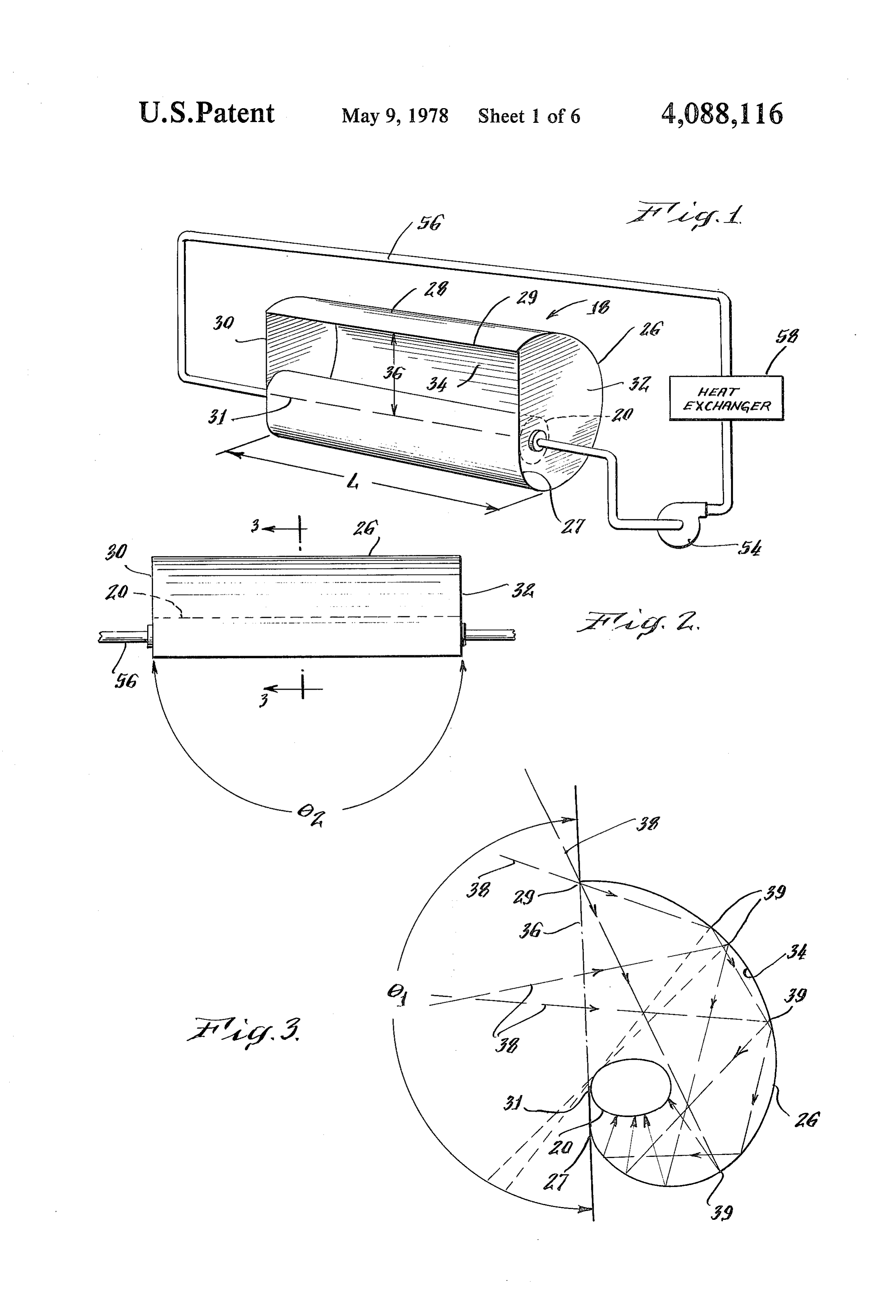
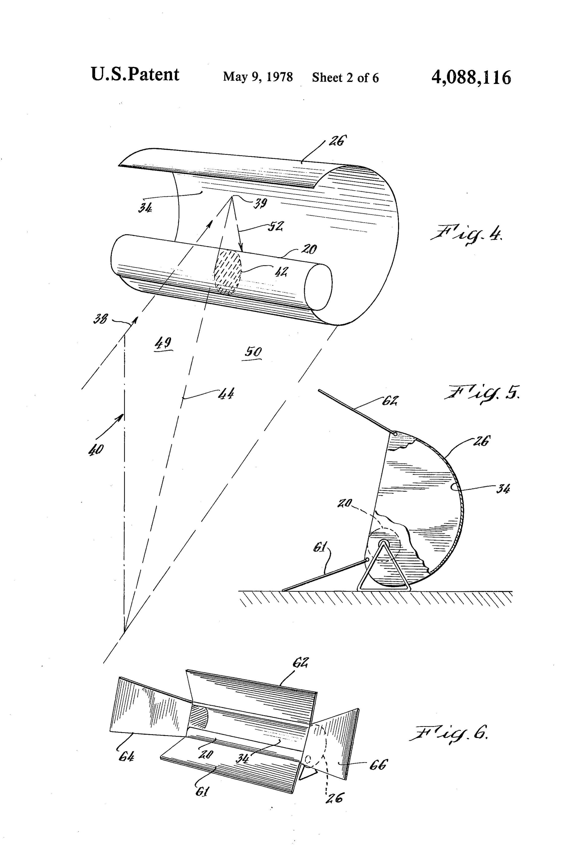
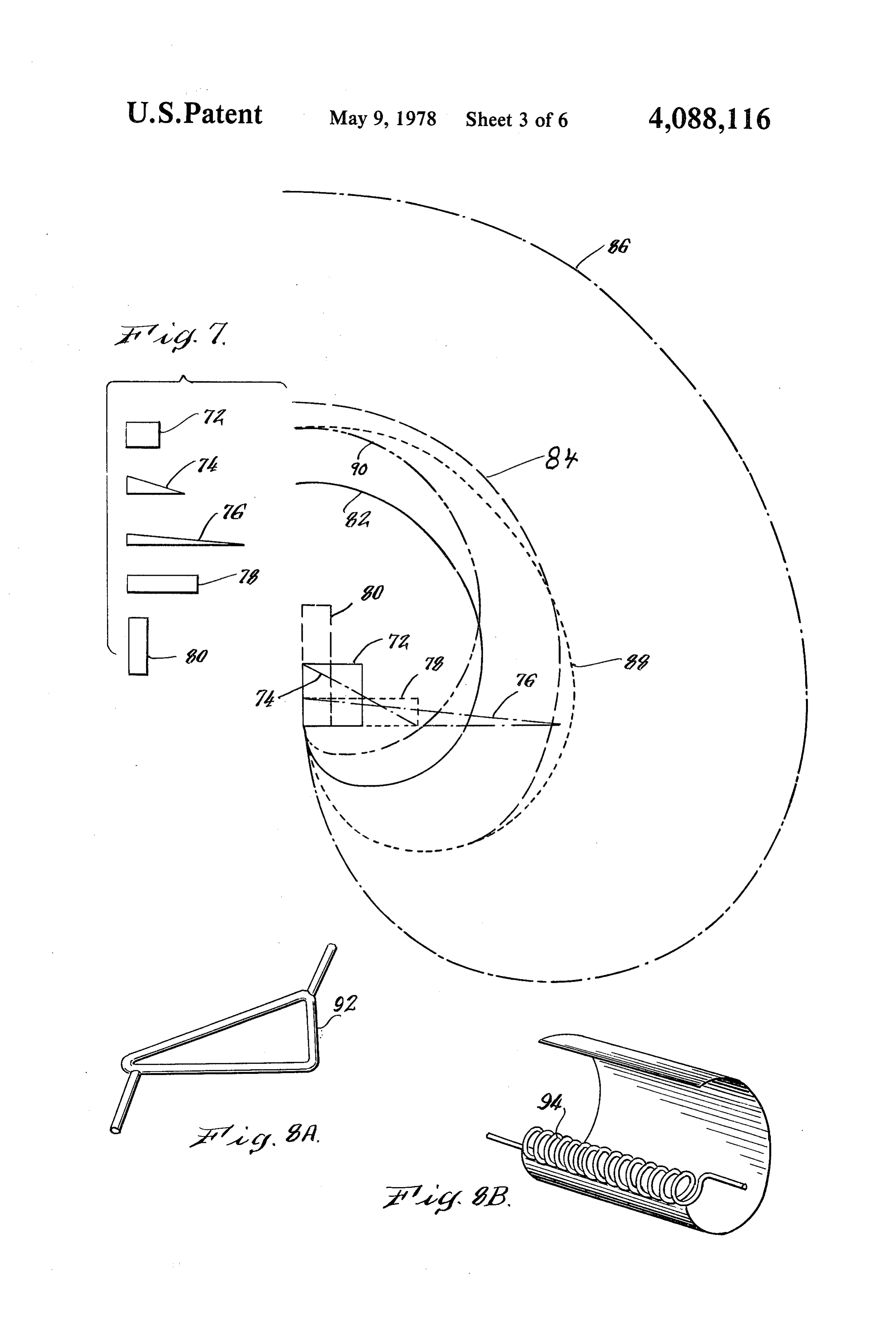
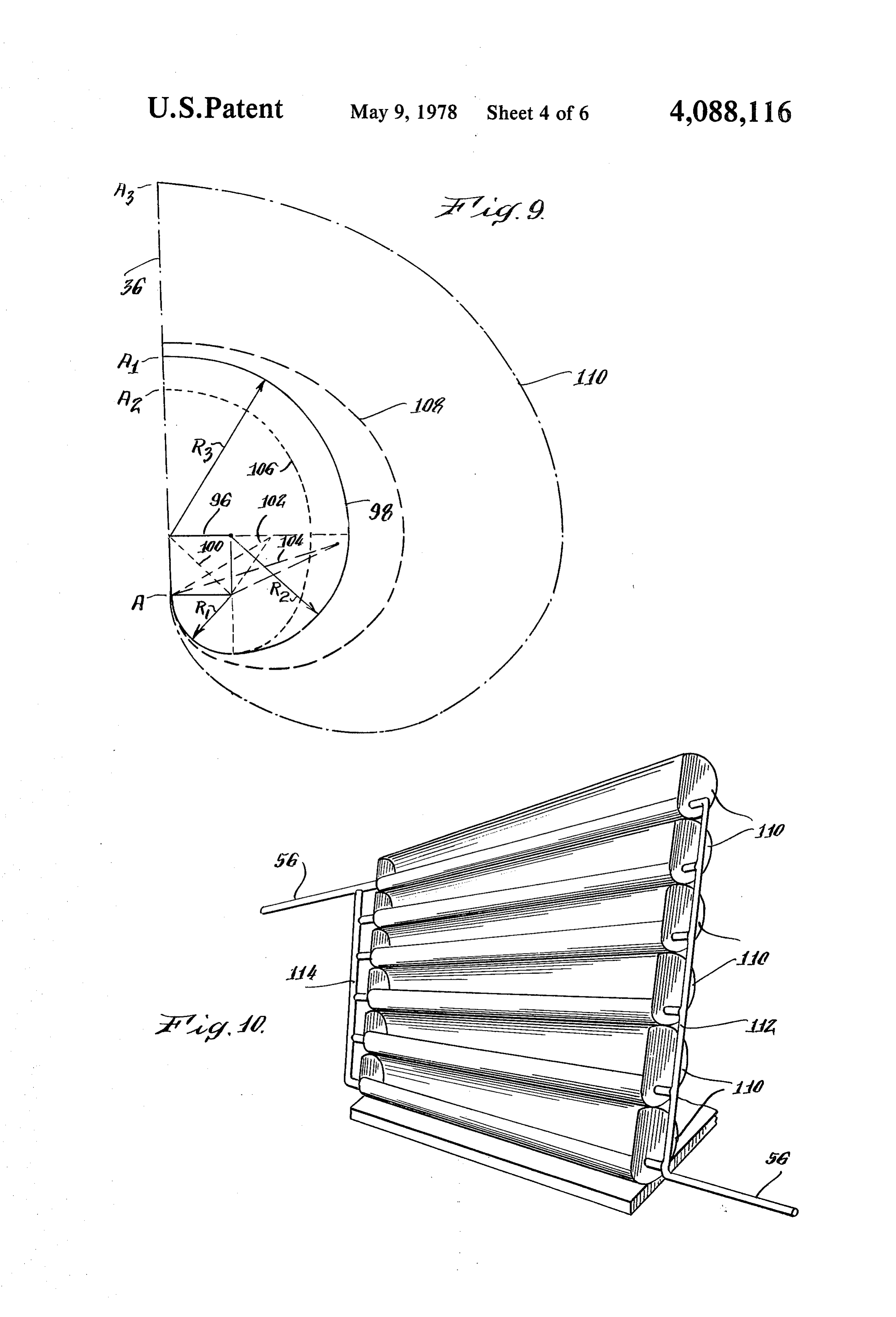
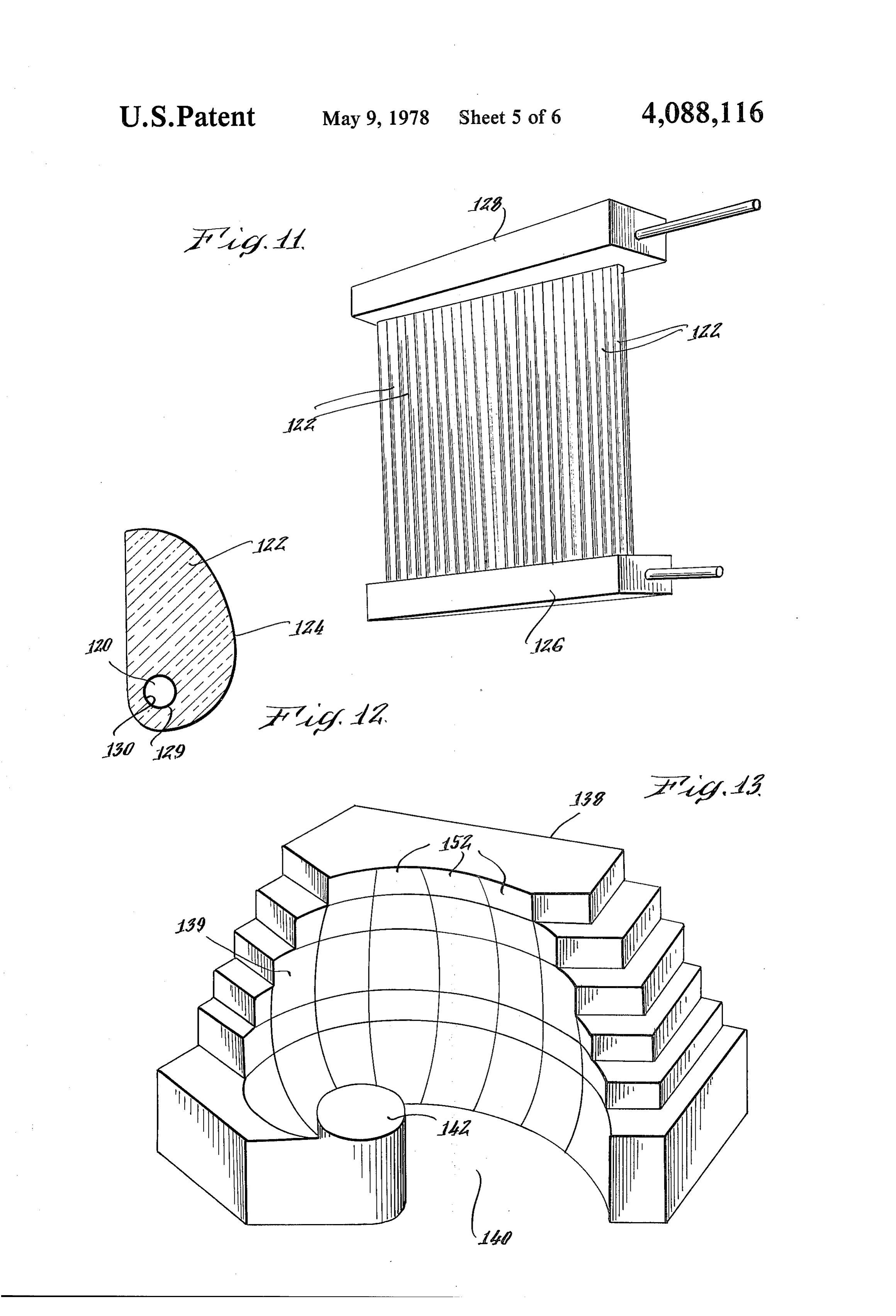
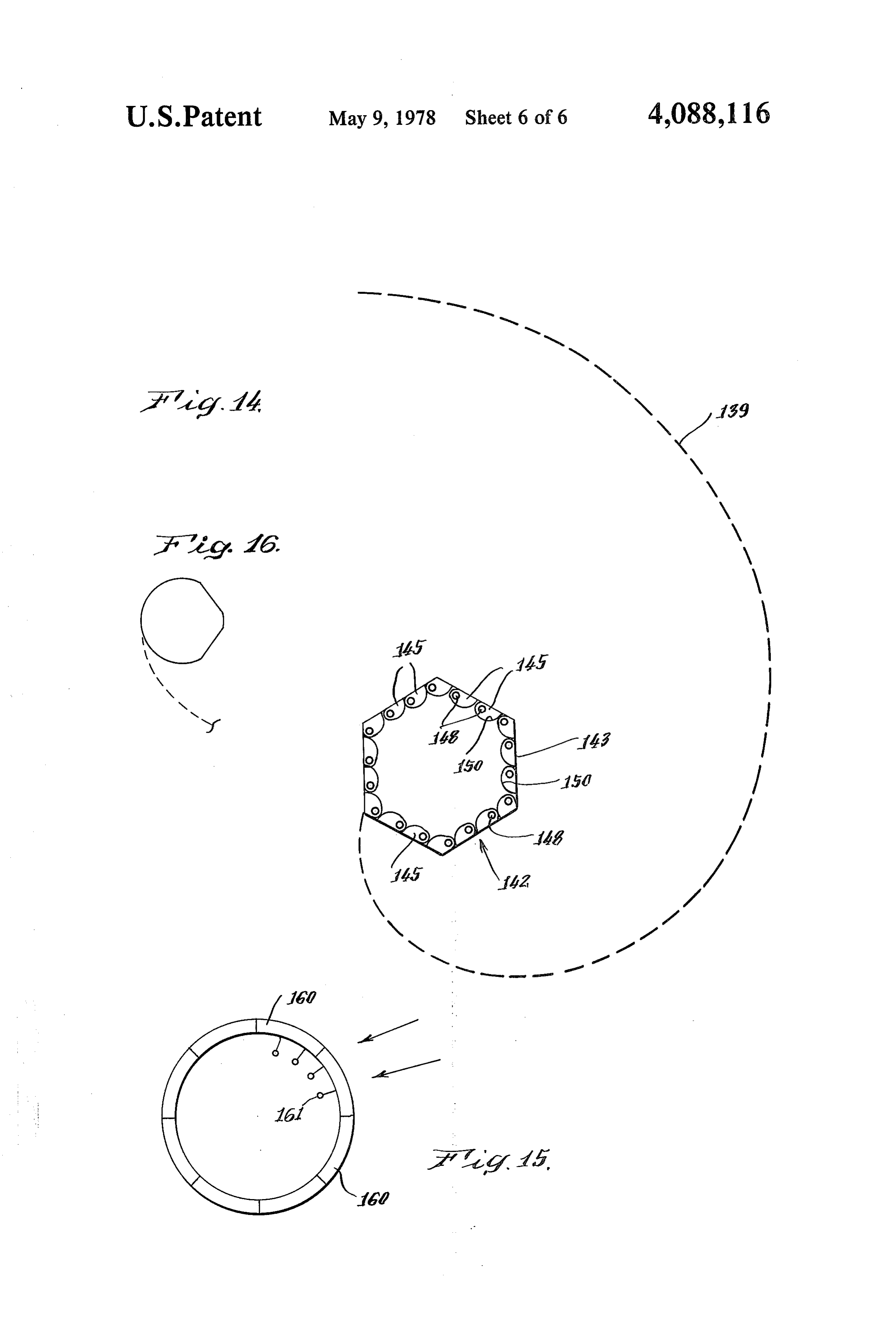
These and other objects and features of the invention 30 is indicated hereinafter. The outer surface of the body will become apparent with reference to the following 20 is preferably blackened by painting or the like in specification and to the drawings wherein: order to provide for efficient absorption of radiant en FIG. 1 is a perspective view of a radiant energy col ergy which is incident thereon. As indicated hereinafter lector apparatus constructed in accordance with fea with respect to FIG. 15, the energy conversion means tures of one embodiment of this invention; 35 alternatively comprises radiant to electrical energy con FIG. 2 is a plan view of the collector of FIG. 1; version means.
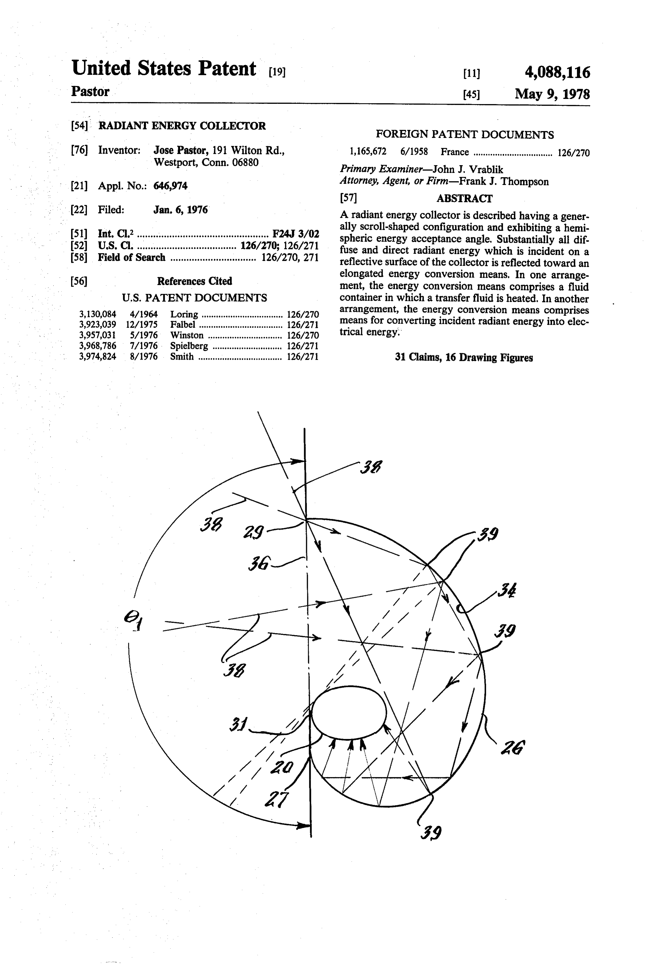
FIG. 3 is an enlarged section view taken along lines A reflective surface means, referenced generally as 3-3 of FIG. 2; 26, is provided and is shown to have a elongated curved FIG. 4 is a fragmentary enlarged view of a segment surface segment 28 extending substantially coexten of the solar collector of FIG. 1; sively in length with the body 20. The reflective surface FIG. 5 is a side view of a solar collector constructed means 26 is also shown in FIG.3 to have a strip segment in accordance with an alternative embodiment for this 27; The surface segment 28, curves in a direction normal invention; or transverse to its length L. This curved surface curves FIG. 6 is a perspective view of the solar collector of continuously. For purposes of this specification and the FIG. 5; 45 appended claims, the expression continuously curved FIG. 7 is a side view of a solar energy collector con surface is understood to mean a curved surface which is structed in accordance with features of this invention uninterrupted by linear segments and which extends and which illustrates a plurality of heat absorbent body substantially from a curve initiation segment 27 to a configurations each having the same cross sectional terminal edge 29. (FIGS. 1 and 3). Segment 27 is pro area and associated curved reflective surfaces; 50 vided to facilitate manufacture of the assembly. It is not FIGS. 8a and 8b are side views of heat absorbent required in all instances and is not shown for example in bodies having alternative means for conveying a heat other views of the drawings. The surface segment 28 is transfer medium; shown to extend rectilinearly in the direction of its FIG. 9 is a side view of alternative body and collector length. End members 30 and 32 are positioned at distal arrangements of different cross sectional areas; 55 ends of the segment 28 and the body 20. Alternatively, FIG. 10 is a perspective view of an assembly of solar the surface segment 28 may also curve in the direction collector elements constructed in accordance with fea of its length and may be open ended as shown hereinaf tures of an embodiment of this invention; ter with respect to FIG. 13. Body 20 is positioned adja FIG. 11 is a perspective view of an alternative assem cent an edge 31 of the segment 27 of the reflective bly of solar collector elements constructed in accor surface means 26 to provide a generally scroll shaped dance with an alternative embodiment of the invention; configuration. The reflective surface means 26 and the FIG. 12 is an enlarged cross sectional view of a col end members 30 and 32 are fabricated of sheet metal, for lector element of FIG. 11; example, and are integrally formed with segments 28 or FIG. 13 is a perspective view of a building structure are alternatively mounted thereto. Alternatively, the constructed in accordance with one embodiment of this 65 surface may be formed of other suitable materials such invention; as plastic and the like. An inner surface 34 of the seg FIG. 14 is a fragmentary cross sectional view of the ment 28 as well as inner surfaces of the segments 30 and structure of FIG. 13; 32 are polished or silvered or otherwise treated for
Page 10
providing a high degree of reflectance therefrom. Thus, circular segment has a plurality of normals which inter when radiant energy impinges upon these surfaces it is sect at one of the vertices of the polygon. The normals efficiently reflected. of successively positioned circular segments intersect The heat absorbent body 20 and the reflective surface successively positioned verticies of the polygon. The means 26 of the generally scroll shaped assembly are radius of each segment is equal to the radius of the positioned for providing that an aperture or window is previous segment increased by a length equal to the formed by these bodies. In FIG. 1, this window is indi length of the side of the polygon between both consecu cated generally by reference numeral 36 while in FIG. tive vertices. The first radius is the length of the first 3 the window is illustrated by a dashed and dotted line side of the polygon. When the convex cross section of 36. This relative positioning of the body 20 and reflec 10 body 20 comprises a continuous curve, the normals to tive surface means 26 to form the window 36 is pro the curved reflective surface are tangent to the perime vided by securing a portion of the periphery of the heat ter of the cross section and the shape of the curved absorbent body 20 to the segment 27 and to the end surface becomes the involute of the shape of the body segments 30 and 32 of the reflective means. This can be 20, accomplished, for example, by welding, by the use of 15 The acceptance angle 6, of FIG. 2 is substantially adhesive, by mechanical, or other suitable means. The 180'. The end walls 30 and 32 are also reflective, as window width is the length of the window measured indicated, and are substantially parallel to each other along the line 36 between an outer edge of the body at and normal to a longitudinal axis of the reflective sur the point of contact with the reflective surface at one face means 26, thereby resulting in an effective length of side and the reflective surface at an opposite edge. 20 the body of infinity. For a collector having a length L In FIG. 3, rays 38 of solar radiant energy represented much greater than the width or diameter of the energy by the lines are illustrated projecting through the win conversion body 20, the acceptance angle 0, will ap dow 36 and are incident on the reflective surface 34 at proach 180 if the end walls are deleted. Thus, the use of points 39. The surface 34 is shaped and is positioned the end walls is also advantageous since they provide relative to the body 20 in accordance with a feature of 25 for efficient collection of energy within practical and the invention for providing that substantially all such reduced dimensions.
incident rays are reflected one or more times from the In addition to the efficient trapping or collection of surface 34 and ultimately impinge. upon the body 20. incident radiant solar energy, this arrangement also This is accomplished by establishing a predetermined provides a relatively wide or hemispheric acceptance geometrical relationship between the energy conver 30 solid angle.
sion body 20 and the surface 34. This geometrical rela A heat transfer means is shown in FIG. 1 for remov tionship is best explained with reference to FIG. 4. A ing thermal energy from the collector. Various forms of plane 40 is shown extending through the energy conver heat transfer means can be utilized. For example, there sion means and defines a cross section 42 of the body 20. is illustrated a means for conveying a heat transfer fluid The section 42 is shown cross hatched for purposes of 35 to the body 20 for removing heat therefrom which clarity in the drawings. The plane 40 is the plane of comprises a conduit 56 (FIG. 1) which conveys a fluid, incidence which is defined by two lines, the incident ray such as a liquid or a gas, to and through the body 20 and 38 and a normal 44 to the surface 34 at the point of to a heat exchanger 58 where thermal energy absorbed incidence 39. Plane 40 is divided by the normal 44 into during residence or transit through the body 20 is re half-planes 49 and 50 respectively. The half-plane 50 in 40 moved. The heat exchanger may comprise a heat oper which a reflected ray 52 and the normal 44 occur is the ated device, such as a space heating unit or the like. A reflection half-plane. The body 20 has a plurality of pump 54 is also provided for causing circulation of the such geometrical cross sections 42 and the body 20 and medium through the conduit 56, the body 20 and the surface segment 28 are each relatively positioned for heat exchanger 58. Circulation can also be provided by providing that every cross section 42 lies in an associ 45 capillary action as discussed hereinafter with respect to ated reflection half-plane. In addition, each normal 44 to FIG. 12. The heat transfer fluid which may comprise a the surface 34 is tangent to or contiguous with a perime liquid such as water, is heated by contact with the inner ter of the cross section 42 of the body 20. Through this surface of the heat absorbent body and by any radiant geometrical relationship, substantially all incident rays energy which penetrates the body 20. Alternatively, the 38 will be reflected one or more times and will impinge 50 body 20 is formed of a translucent material such as glass on the energy conversion means 20. Efficient solar radi or a light transmitting polymer plastic. In this case the ant energy collection is effected by thus providing a heat transfer fluid is adapted to be directly heated by reflective surface and energy conversion body configul radiant energy. This is provided in one arrangement by ration and by positioning these components for provid utilizing a colored, preferably black, fluid. ing that for any incident ray 38, all sections 42 are lo 55 There is illustrated in FIG. 5 an alternative embodi cated in the half-plane 50 containing reflected rays. ment wherein the fluid containing means 20 has a circu Thus this configuration provides an acceptance angle lar cross sectional area. The surface 34 of the reflective 0 (FIG. 3) of 180. surface means 26 is shaped to provide a curved surface The cross sectional configuration of the energy con which is the involute of the circular cross sectional area version body 20 is preferably convex. Various convex of body 20. The involute for the cross sectional area of configurations can be employed, as is described herein body 20 will provide a reflective surface in which a after and the curved reflective surface segment 28 is normal to the surface 34 at the point of incidence of an shaped to satisfy the above described geometrical rela impinging ray will be tangent to or intersect the body tionship. When the convex cross section of body 20 20. The arrangement of FIG. 5 is further advantageous comprises a polygon having a plurality of verticies 65 in that light reflective shields 61 and 62, each having successively positioned about the cross section perime reflective surfaces, enhance the radiant energy gather ter, the continuous curved surface segment 28 com ing characteristics of the energy collector. As illus prises a plurality of curved circular segments. Each trated in FIG. 6, reflectors 64 and 66 are also provided.
Page 11
In addition to the oblong cross sectional configura ments comprise elongated tubular bodies 92 and 94 tion of the heat absorbent body of FIG. 1 and the circu formed into coils as shown in FIGS. 8a and 8b respec lar cross sectional configuration of the body 20 of FIG. tively. In FIG. 8a the coil cross section is a polygon and 5, the body may also be shaped into other cross sec conforms to a triangle while in FIG. 8b the coil cross tional configurations. One characteristic of the radiant section is curved and conforms to a circle. The coil energy collector of this invention is that the width of cross section can also be shaped to conform to other the window 36 of FIG. 3 is equal in length to the perim convex polygonal or curved configurations. eter of the convex body 20. An increase in temperature FIG. 9 illustrates an arrangement wherein the tem AT of the heat transfer fluid in the body 20 is related to perature is increased by reducing the size of the body. the body configuration and is given by: O The body 96 is associated with reflector 98 and bodies 100, 102 and 104 are associated with reflectors 106, 108
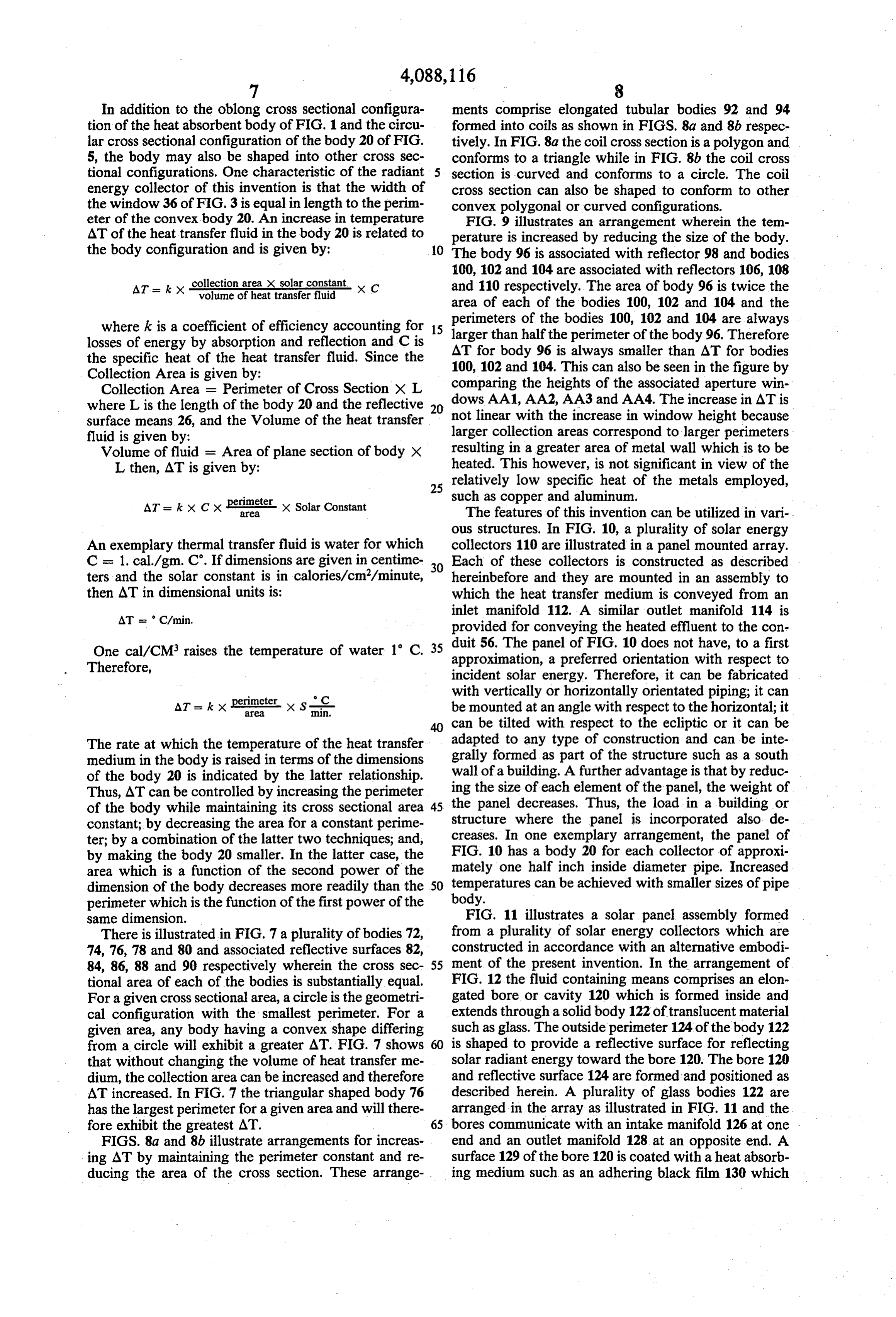
ATs k X collection area X solar constant volume of heat transfer fluid X C and 110 respectively. The area of body 96 is twice the area of each of the bodies 100, 102 and 104 and the perimeters of the bodies 100, 102 and 104 are always where k is a coefficient of efficiency accounting for 15 larger losses of energy by absorption and reflection and C is AT forthan half the perimeter of the body 96. Therefore body 96 is always smaller than AT for bodies the specific heat of the heat transfer fluid. Since the 100, 102 and 104. This can also be seen in the figure by Collection Area is given by: comparing the heights of the associated aperture win Collection Area = Perimeter of Cross Section X L where L is the length of the body 20 and the reflective 20 dows AA1, AA2, AA3 and AA4. The increase in AT is surface means 26, and the Volume of the heat transfer not linear with the increase in window height because fluid is given by: larger collection areas correspond to larger perimeters Volume of fluid = Area of plane section of body X resulting in a greater area of metal wall which is to be L then, AT is given by: heated. This however, is not significant in view of the 25 relatively low specific heat of the metals employed, such as copper and aluminum.
AT = kx cx Peter-x Solar Constant The features of this invention can be utilized in vari ous structures. In FIG. 10, a plurality of solar energy
An exemplary thermal transfer fluid is water for which collectors 110 are illustrated in a panel mounted array. C = 1. cal/gm. C. If dimensions are given in centime 30 Each of these collectors is constructed as described ters and the solar constant is in calories/cm/minute, hereinbefore and they are mounted in an assembly to then AT in dimensional units is: which the heat transfer medium is conveyed from an inlet manifold 112. A similar outlet manifold 114 is
provided for conveying the heated effluent to the con
One cal/CM. raises the temperature of water 1 C. 35 duit 56. The panel of FIG. 10 does not have, to a first approximation, a preferred orientation with respect to
Therefore, incident solar energy. Therefore, it can be fabricated perimeter C with vertically or horizontally orientated piping; it can
AT = k X is x Sri be mounted at an angle with respect to the horizontal; it can be tilted with respect to the ecliptic or it can be
The rate at which the temperature of the heat transfer adapted to any type of construction and can be inte medium in the body is raised in terms of the dimensions grally formed as part of the structure such as a south of the body 20 is indicated by the latter relationship. wall of a building. A further advantage is that by reduc Thus, AT can be controlled by increasing the perimeter ing the size of each element of the panel, the weight of of the body while maintaining its cross sectional area 45 the panel decreases. Thus, the load in a building or constant; by decreasing the area for a constant perime structure where the panel is incorporated also de ter; by a combination of the latter two techniques; and, creases. In one exemplary arrangement, the panel of by making the body 20 smaller. In the latter case, the FIG. 10 has a body 20 for each collector of approxi area which is a function of the second power of the mately one half inch inside diameter pipe. Increased dimension of the body decreases more readily than the 50 temperatures can be achieved with smaller sizes of pipe body.
perimeter which is the function of the first power of the same dimension. FIG. 11 illustrates a solar panel assembly formed There is illustrated in FIG. 7 a plurality of bodies 72, from a plurality of solar energy collectors which are 74, 76, 78 and 80 and associated reflective surfaces 82, constructed in accordance with an alternative embodi 84, 86, 88 and 90 respectively wherein the cross sec 55 ment of the present invention. In the arrangement of tional area of each of the bodies is substantially equal. FIG. 12 the fluid containing means comprises an elon For a given cross sectional area, a circle is the geometri gated bore or cavity 120 which is formed inside and cal configuration with the smallest perimeter. For a extends through a solid body 122 of translucent material given area, any body having a convex shape differing such as glass. The outside perimeter 124 of the body 122 from a circle will exhibit a greater AT. FIG. 7 shows 60 is shaped to provide a reflective surface for reflecting that without changing the volume of heat transfer me solar radiant energy toward the bore 120. The bore 120 dium, the collection area can be increased and therefore and reflective surface 124 are formed and positioned as AT increased. In FIG. 7 the triangular shaped body 76 described herein. A plurality of glass bodies 122 are has the largest perimeter for a given area and will there arranged in the array as illustrated in FIG. 11 and the fore exhibit the greatest AT. 65 bores communicate with an intake manifold 126 at one FIGS. 8a and 8b illustrate arrangements for increas end and an outlet manifold 128 at an opposite end. A ing AT by maintaining the perimeter constant and re surface 129 of the bore 120 is coated with a heat absorb ducing the area of the cross section. These arrange ing medium such as an adhering black film 130 which
Page 12
becomes heated upon impingement by solar radiation ally collecting radiant solar energy and in addition it is and transfers heat to the liquid flowing in the capillary. stylized for appearance.
As an alternative to forming the film 130 on the surface In FIG. 15, the energy conversion means is shown to of the bore, the heat transfer fluid may comprise a dark, comprise means for converting radiant energy into elec heat absorbent fluid which, for example, is colored trical energy. FIG. 15 illustrates a cross section of the black. body 20 having a plurality of solar cells 160 supported The bore 120, in accordance with one embodiment of in an array on the body. The solar cells comprise photo the invention has a relatively small cross sectional area sensitive semiconductor material adapted to generate an for providing motion of the fluid therein as a result of electric potential when radiant energy impinges on a capillary forces. Because of this capillary construction, 10 surface of the cell. The cells each include output leads the fluid will rise vertically within the capillary tubing 161 which can be coupled in parallel, in series or in without external pumping aid. In FIG. 11, each of the combinations of these electrical connections to provide bores 120 of the glass bodies 122 communicates with the the desired output potential and source impedance. inlet manifold and with the outlet manifolds. This ar rangement can theoretically provide a AT of 60°C/min. 15 ited on the surface ofsemiconductor
Alternatively, the material is depos the body 20 to provide a continu
FIG. 13 illustrates a building structure 138 con ous extended cell on which radiant energy impinges or structed in accordance with the solar energy collecting is segmented to satisfy particular needs. features of this invention. The structure which may An improved apparatus has thus been described for comprise a residential, office or industrial building in the collection of diffused and direct radiant energy. The cludes a vertically extending reflecting wall surface 139 20 apparatus is advantageous in that it provides highly and a central courtyard 140 in which is located a cylin efficient collection of the energy at high acceptance drically shaped, vertically extending fluid containing angles. The described apparatus is further advantageous means comprising a heat absorbent body 142. In one example, the heat transfer fluid comprises water, which in that it is incorporated into various arrangements is conveyed to the body 142 and is flowed over the 25 including panel assemblies and building structures. inner surfaces of the body where it is heated by transfer While I have described particular embodiments of my of thermal energy from the inner surface of this body. It invention, it will be apparent to those skilled in the art is then conveyed to a heat exchanger for heating the that variations may be made thereto without departing building structure or to other heat exchanging utility from the spirit of the invention and the scope of the devices. 30 appended claims.
Alternatively as illustrated in FIG. 14, a wall 143 of What is claimed is:
the body 142 may comprise a plurality of vertically 1. A radiant energy collector comprising: orientated solar collectors 145 each of which is posi A. an elongated reflective surface means having a tioned adjacent the wall 143 for impingement by light curved surface for reflecting radiant energy which reflected from the principal reflective surface 139. The 35 is incident on said curved surface, said surface solar collectors 145 comprise vertically orientated bod means having a length and an edge, said edge ex ies 148 which may be metal pipes and reflective surfaces tending in a direction of said length, and said 150 constructed in accordance with the invention as curved surface curving continuously in a direction described hereinbefore. The solar collectors may also normal to said length;
comprise collectors as described hereinbefore with re B. an elongated energy conversion means comprising spect to FIGS. 11 and 12. a body extending in the direction of said length The vertical wall 139 comprises a reflective surface adjacent said edge and positioned with respect to which has a curved, configuration as shown in the plan said reflective surface means for impingement by section of FIG. 14, and which is shaped as described radiant energy which is reflected from said curved hereinbefore. Its surface is formed of semitransparent 45 surface toward said body; window material. A portion of incident radiant solar C. said body having a plurality of cross sections energy is transmitted for illuminating the interior of the which are defined by the intersection of the body building and a portion is reflected, as described herein with planes of incidence of substantially all radiant before, toward the heat absorbent body 142. energy impinging on said curved surface; The wall 139 is also curved in a vertical direction for 50 D. said reflective curved surface having a plurality of principally focusing direct incident radiant energy at reflective half-planes each defined by a normal to the body 142 and compensating partially for the non said curved surface and by a reflected ray from said parabolic segments of the reflective surface means 26 of surface;
FIG. 1. As illustrated in FIG. 13, the wall includes a E. said body and said reflective curved surface rela plurality of meridional sections 152. Each meridional 55 tively positioned for providing that said cross sec section is curved in a vertical plane and is defined by a tions are located within said reflected half-planes vertical plane that contains all the normals to the hori and said normals are contiguous with peripheries of zontal sections of the wall at the point of intersection of said cross sections;
the meridional plane with the horizontal section. Each F. said relative positioning of said body and curved meridional section is parabolic shaped having a focal 60 surface forming an aperture through which radiant pointlocated at the intersection of the meridional plane, energy propagates and is incident on said surface, the body 142 and an upper horizontal plane of the body said aperture having a width extending in a direc 142. The maximum height and length of the body 142 is tion generally normal to the length of said surface defined by the latitude of the building location. Thus, and which width is substantially equal in length to the body can be supported off the ground, and, the 65 the perimeter of said body.
incident solar energy on the body can vary with the 2. A solar radiant energy collector in accordance position of the sun in the sky. The building wall surface with claim 1 wherein said energy conversion means thus provides a combination of techniques for function comprises photoresponsive means positioned along said
Page 13
body for providing an electrical potential when radiant 21. The solar energy collector of claim 19 wherein energy is incident thereon. said cross sectional configuration comprises a square. 3. A radiant energy collector in accordance with 22. The solar energy collector of claim 19 wherein claim 1 wherein a body is formed by a plurality of indi said cross sectional configuration comprises a triangle. vidual solar energy collectors arrayed along a perimeter 23. The solar energy collector of claim 19 wherein of an enclosed configuration and means are provided said polygonal cross sectional configuration comprises a for removing energy from each of said individual solar plurality of verticies and wherein said verticies are lo energy collectors. cated successively about the periphery of said cross 4. The solar energy collector of claim 1 including first sectional configuration, said curved reflective surface and second end wall members positioned in opposite 10 includes a plurality of curved segments positioned suc distal locations of said reflective surface and body. cessively in a direction normal to the length of said 5. A solar radiant energy collector in accordance surface, each of said curved segments having a plurality with claim 1 wherein said body comprises an elongated of normals to the surface of the segment, said normals of fluid containing means for positioning a heat transfer 15 any one associated segment extending from said associ fluid for heating said fluid by radiant energy which is ated segment to a single vertex, and the normals of reflected from said surface. successively positioned curved segments extending to 6. The solar radiant energy collector of claim 5 in successively positioned verticies.
cluding heat exchange means for conveying a heat 24. The solar energy collector of claim 17 wherein said convex cross sectional configuration comprises a transfer fluid to and from said elongated fluid contain 20 continuous ing means. curve.
7. The solar energy collector of claim 5 wherein said said25.cross
The solar energy collector of claim 24 wherein sectional configuration comprises a circle.
fluid containing means comprises a tubular conduit formed into a coil having a convex cross sectional con said 26. The solar energy collector of claim 24 wherein figuration. curved reflective surface is shaped to provide a 8. The solar energy collector of claim 5 wherein said 25 continuously said curved curved surface which is the involute of cross section.
fluid containing means comprises a tubular conduit 27. The solar energy collector of claim 1 wherein said formed into a coil having a triangular cross sectional elongated body is vertically extending and said reflec configuration.
9. The solar energy collector of claim 5 wherein said 30 surface of a building structure. a vertically extending tive surface means comprises fluid containing means comprises a tubular conduit formed into a coil having a circular cross sectional said28.vertically
The solar energy collector of claim 27 wherein extending building surface is curved in a configuration. vertical direction for focusing solar energy at said verti 10. The solar energy collector of claim 5 wherein said cally extending body.
fluid containing means comprises an elongated radiant 35 29. A solar panel comprising:
energy absorbent conduit having a surface thereof A. an array of solar collectors; which is adapted to absorbent solar radiant energy. B. Each of said solar collectors comprising an elon 11. The solar radiant energy collector of claim 10 gated reflective surface means having a curved wherein said conduit is formed of a heat absorbent surface for reflecting radiant energy which is inci. metal.
12. The radiant energy collector of claim 5 wherein 40 dent thereon, said reflective surface means having a length and an edge thereof, said curved surface said fluid containing means comprises a translucent extending in a direction of said length and continu body and said heat transfer medium comprises a fluid ously curved in a direction normal to a length of which is colored for heat absorption upon impingement said surface, and an elongated energy conversion by radiant energy. 45 means having a body extending generally parallel 13. The radiant energy collector of claim 12 wherein to the length of said surface means and adjacent said fluid is colored black. said edge and positioned with respect to said 14. The radiant energy collector of claim 5 wherein curved reflective surface for impingement by radi said fluid containing means comprises a translucent ant energy which is reflected from said curved body having a bore formed therein and said reflective 50 surface toward said body, said body having a plu surface comprises a surface of said translucent body. rality of cross sections which are defined by the 15. The radiant energy collector of claim 14 wherein intersection of the body of planes of incidence of said bore has a surface thereof and a film of heat absor substantially all radiant energy impinging on said bent material is positioned on said surface. curved surface, said reflective curved surface hav 16. The radiant energy collector of claim 14 wherein 55 ing a plurality of reflection half-planes each defined said bore has a cross sectional area having a dimension by a normal to said curved surface and by a re for causing capillary motion of said fluid in said bore. flected ray from said curved surface, said body and 17. The radiant energy collector of claim 1 wherein said reflective curved surface relatively positioned said body has a convex cross sectional configuration for providing that said cross sections are located which extends in a direction normal to the length of said 60 within said reflected half-planes and said normal is body. contiguous with a periphery of said cross section, 18. The solar energy collector of claim 17 wherein intake and outlet manifold means for conveying a said cross sectional configuration comprises a combina heat transfer medium thereto, and, said relative tion of linear and curved segments. positioning of said body and curved surface form 19. The radiant energy collector of claim 17 wherein 65 ing an aperture through which radiant energy said cross sectional configuration comprises a polygon. propagates and is incident on said surface, said 20. The solar energy collector of claim 19 wherein aperture having a width extending in a direction said cross sectional configuration comprises a rectangle. generally normal to the length of said surface and
Page 14
which width is substantially equal in length to the abore formed therein and said reflective curved surface perimeter of said body is provided by a surface of said translucent body. 31. The solar collector array of claim 30 wherein said 30. The solar energy collector array of claim 29 bores are of capillary dimensions. wherein said body comprises a translucent body having 5 a

Provenance
- Collection
- Cited prior art
- Original PDF
- patentimages.storage.googleapis.com →
- Filed
- 1976-01-06
- Pages
- 14
- Method
- pdftotext (the PDF's own text layer) + pdftoppm 300dpi page scans
- Source
- Google Patents bibliographic record
- Granted
- 1978-05-09
- Inventors
- Jose Pastor
- Transcribed from
- patentimages.storage.googleapis.com →