patent · US3747907
Night stream cooling system and method
24 July 1973
Page 1 — bibliographic record
United States Patent (19) 11 3,747,907 Anderson (45) July 24, 1973 54 NIGHT STREAM COOLING SYSTEM AND 1,233,119 7/1917 Parker................................ 2611151 METHOD 1,828,528 10/1931 Fohl...................................... 165145
76 Inventor: James H. Anderson, 1615 Hillock 3,254,702 6/1966 Thomason.... ... 165148 Ln., York, Pa. 17403 3,295,591 1/1967 Thomason .... we a as 165/1 22 Filed: June 28, 1972 3,498,072 3/1970 Stiefel................................... 621 118 (21) Appl. No.: 267,198 Primary Examiner-Tim R. Miles
Related U.S. Application Data Attorney-John W. Malley et al.
63 Continuation of Ser. No. 18,269, March 10, 1972, 57 ABSTRACT abandoned.
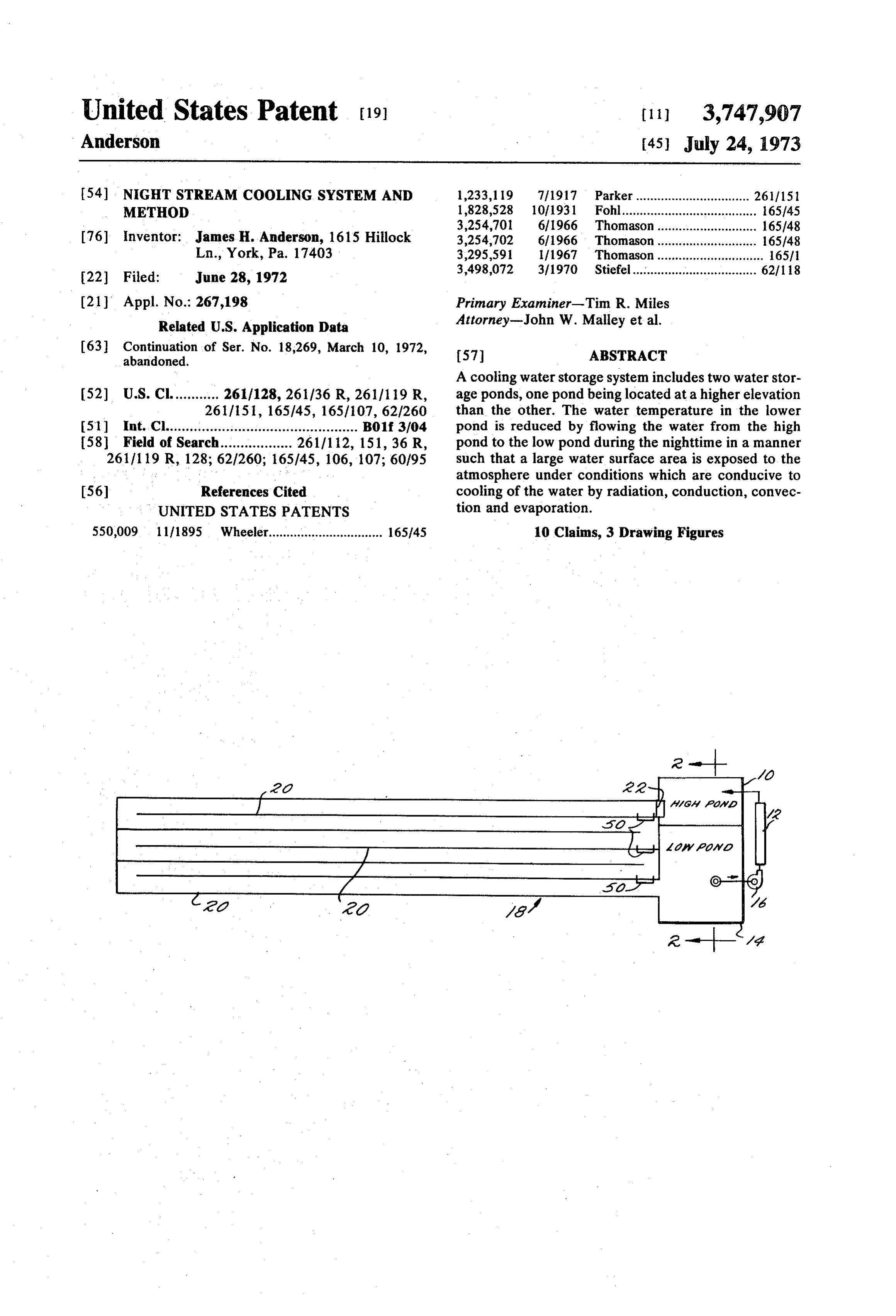
A cooling water storage system includes two water stor 52) U.S. Cl............ 2611128, 261/36 R, 2611119 R, age ponds, one pond being located at a higher elevation 261/151, 165/45, 165/107, 62/260 than the other. The water temperature in the lower (51) Int. Cl................................................ B01f 3/04 pond is reduced by flowing the water from the high 58 Field of Search.................. 26111 12, 151, 36 R, pond to the low pond during the nighttime in a manner 2611119 R, 128; 62/260; 165/45, 106, 107; 60/95 such that a large water surface area is exposed to the atmosphere under conditions which are conducive to 56 References Cited cooling of the water by radiation, conduction, convec UNITED STATES PATENTS tion and evaporation.
550,009 1 1/1895 Wheeler................................ 165145 10 Claims, 3 Drawing Figures
Page 2
Drawing sheet — no readable text.
Page 3
Drawing sheet — no readable text.
Page 4
NIGHT STREAM COOLNG SYSTEMAND provement of 20% for a reduction in heat sink tempera
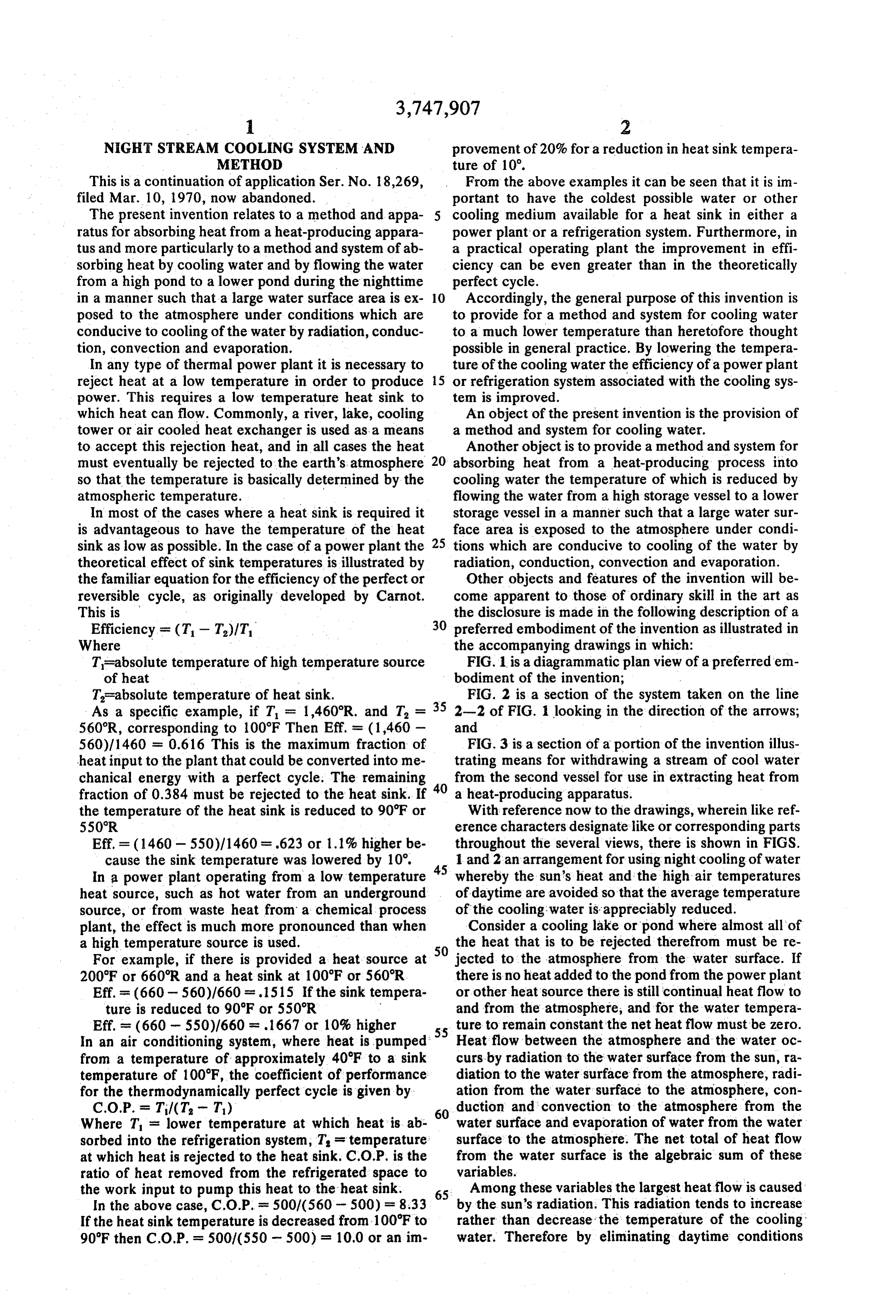
This is a continuation of application Ser. No. 18,269, From the above examples it can be seen that it is im filed Mar. 10, 1970, now abandoned. portant to have the coldest possible water or other The present invention relates to a method and appa cooling medium available for a heat sink in either a ratus for absorbing heat from a heat-producing appara power plant or a refrigeration system. Furthermore, in tus and more particularly to a method and system of ab a practical operating plant the improvement in effi sorbing heat by cooling water and by flowing the water ciency can be even greater than in the theoretically from a high pond to a lower pond during the nighttime perfect cycle.
in a manner such that a large water surface area is ex O Accordingly, the general purpose of this invention is posed to the atmosphere under conditions which are to provide for a method and system for cooling water conducive to cooling of the water by radiation, conduc to a much lower temperature than heretofore thought tion, convection and evaporation. possible in general practice. By lowering the tempera In any type of thermal power plant it is necessary to ture of the cooling water the efficiency of a powerplant reject heat at a low temperature in order to produce 15 or refrigeration system associated with the cooling sys power. This requires a low temperature heat sink to tem is improved.
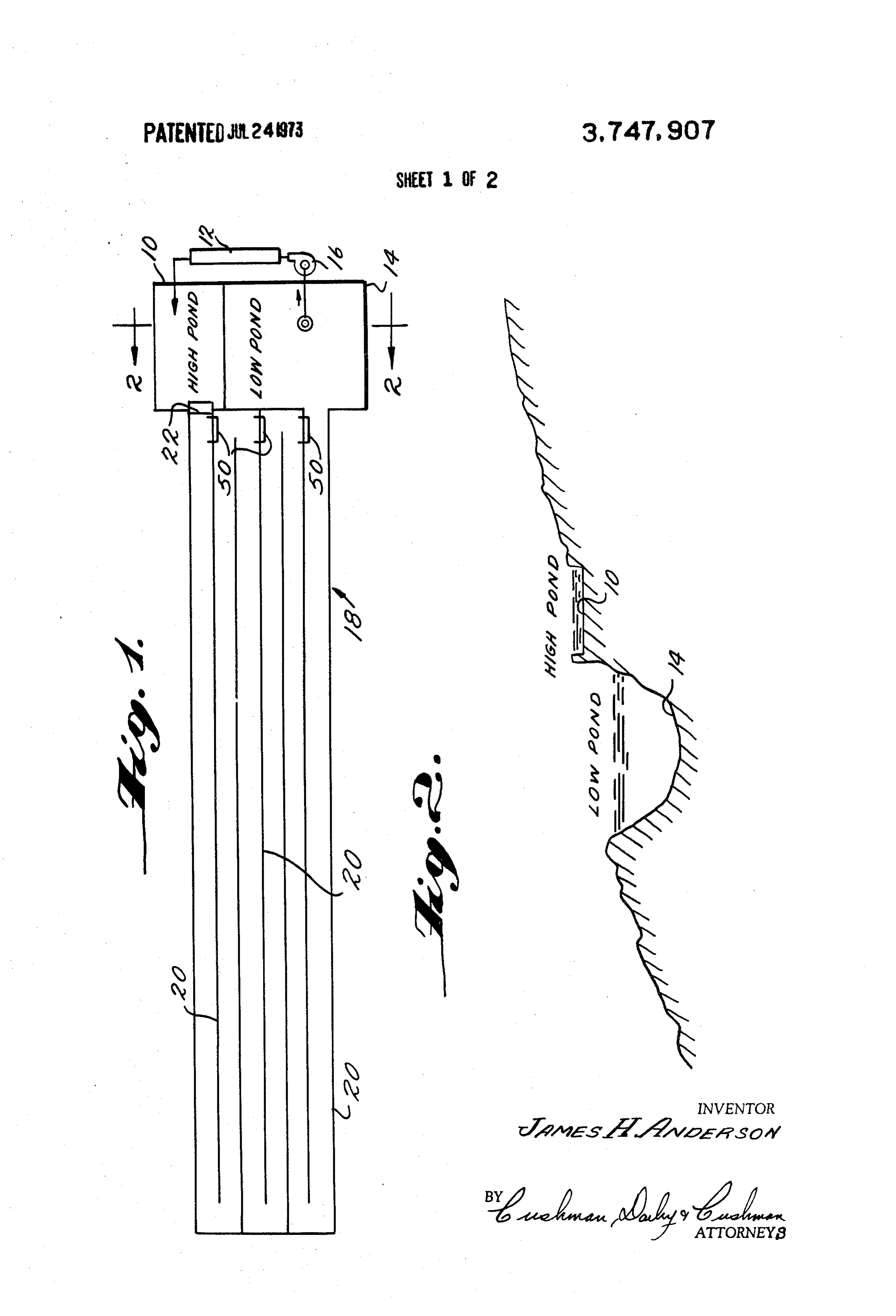
which heat can flow. Commonly, a river, lake, cooling An object of the present invention is the provision of tower or air cooled heat exchanger is used as a means a method and system for cooling water. to accept this rejection heat, and in all cases the heat Another object is to provide a method and system for must eventually be rejected to the earth's atmosphere 20 absorbing heat from a heat-producing process into so that the temperature is basically determined by the cooling water the temperature of which is reduced by atmospheric temperature. flowing the water from a high storage vessel to a lower In most of the cases where a heat sink is required it storage vessel in a manner such that a large water sur is advantageous to have the temperature of the heat face area is exposed to the atmosphere under condi sink as low as possible. In the case of a power plant the 25 tions which are conducive to cooling of the water by theoretical effect of sink temperatures is illustrated by radiation, conduction, convection and evaporation. the familiar equation for the efficiency of the perfector Other objects and features of the invention will be reversible cycle, as originally developed by Carnot. come apparent to those of ordinary skill in the art as This is the disclosure is made in the following description of a Efficiency = (T-T)/T, 30 preferred embodiment of the invention as illustrated in Where the accompanying drawings in which: T=absolute temperature of high temperature source FIG. 1 is a diagrammatic plan view of a preferred 'em of heat bodiment of the invention;
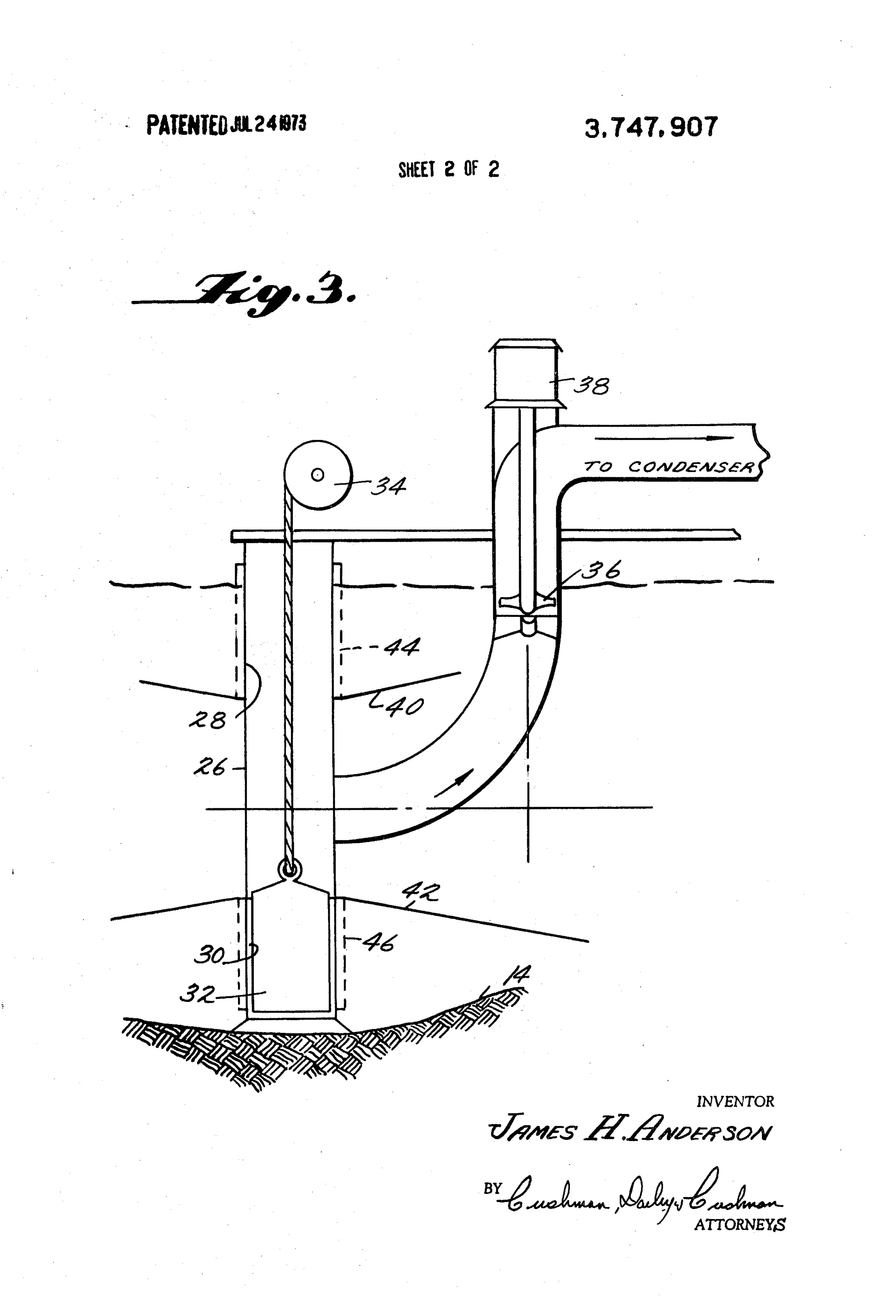
T=absolute temperature of heat sink. FIG. 2 is a section of the system taken on the line As a specific example, if T = 1,460R. and T. 35 2-2 of FIG. 1 looking in the direction of the arrows; 560°R, corresponding to 100°F Then Eff. = (1,460 - and 560)/1460 = 0.616. This is the maximum fraction of FIG. 3 is a section of a portion of the invention illus heat input to the plant that could be converted into me trating means for withdrawing a stream of cool water chanical energy with a perfect cycle. The remaining from the second vessel for use in extracting heat from fraction of 0.384 must be rejected to the heat sink. If 40 a heat-producing apparatus.
the temperature of the heat sink is reduced to 90°F or With reference now to the drawings, wherein like ref 550°R erence characters designate like or corresponding parts Eff. = (1460-550)/1460 =.623 or 1.1% higher be throughout the several views, there is shown in FIGS. cause the sink temperature was lowered by 10. 1 and 2 an arrangement for using night cooling of water In a power plant operating from a low temperature 45 whereby the sun's heat and the high air temperatures heat source, such as hot water from an underground of daytime are avoided so that the average temperature source, or from waste heat from a chemical process of the cooling water is appreciably reduced. plant, the effect is much more pronounced than when Consider a cooling lake or pond where almost all of a high temperature source is used. the heat that is to be rejected therefrom must be re For example, if there is provided a heat source at 50 jected to the atmosphere from the water surface. If 200°F or 660R and a heat sink at 100°F or 560R there is no heat added to the pond from the power plant Eff. = (660 - 560)/660 = .1515. If the sink tempera or other heat source there is still continual heat flow to ture is reduced to 90°F or 550R and from the atmosphere, and for the water tempera
ture to remain constant the net heat flow must be zero.
In an air conditioning system, where heat is pumped Heat flow between the atmosphere and the water oc from a temperature of approximately 40°F to a sink curs by radiation to the water surface from the sun, ra temperature of 100°F, the coefficient of performance diation to the water surface from the atmosphere, radi for the thermodynamically perfect cycle is given by ation from the water surface to the atmosphere, con C.O.P. = T/(T-T) 60 duction and convection to the atmosphere from the Where T = lower temperature at which heat is ab water surface and evaporation of water from the water sorbed into the refrigeration system, T = temperature surface to the atmosphere. The net total of heat flow at which heat is rejected to the heat sink. C.O.P. is the from the water surface is the algebraic sum of these ratio of heat removed from the refrigerated space to variables.
the work input to pump this heat to the heat sink. 65 Among these variables the largest heatflow is caused In the above case, C.O.P. = 500/(560-500) = 8.33 by the sun's radiation. This radiation tends to increase If the heat sink temperature is decreased from 100°F to rather than decrease the temperature of the cooling 90°F then C.O.P. = 500/(550 - 500) = 10.0 or an im water. Therefore by eliminating daytime conditions
Page 5
from the cooling system the average temperature of the Tests of the system and method of this invention have cooling water can be very appreciably reduced. been conducted to illustrate that the average tempera The system of this invention which is utilized for ture to which the water is cooled is considerably higher night cooling of water includes a first storage vessel or when the system is utilized so that water flows from the pond 10 for receiving a stream of relatively warm cool upper to the lower pond for 24 hour periods as Nor ing water which has passed in heat-exchange relation mally, to when the system is used only during nighttime ship with a heat-producing apparatus through a con hours or for twelve hour periods. An important factor denser 12 from a second storage vessel 14 and through and disadvantage inherent in the method of cooling the means 16 for withdrawing a stream of cool water from water as described over 24 hour periods is that the the second vessel. The system further includes means 10 highest temperature of the cooling water results when 18 for enabling the flow of water from the first vessel power needs are greatest in the afternoon and evening. 10 to the second vessel 14 and for simultaneously cool Temperature records of actual operation of the system ing the flowing water by radiation, conduction, convec confirm that this is the case. The probable difference tion and evaporation to the ambient atmosphere. This 15 at peak load time of cooling water temperature as ob flowing means 18 includes an open-top inclined chan tained by the night stream cooling method when com nel 20 which connects the vessels 10 and 14 and which pared to the continuous operation of the system is is adapted to expose a very large surface area of the about 15°. This makes a very important difference in flowing water to the ambient atmosphere. The flowing output Ost, capacity of a power plant when it is needed means also includes a valve means 22, e.g. a bascule or other suitable type of gate, for retaining the water in 20 tinuously
The pump 16 takes water from the lower vessel con at a predetermined rate. The primary flow the first vessel 10 during the daytime and for enabling the flow of water from the first vessel 10 into the chan from the upper vessel through the channel 20 occurs, nel 20 at night, for example, from 6 PM to 6 AM for nighttime cooling The second storage vessel 14 is made larger and 25 and6 also occurs at a predetermined rate. From 6 AM deeper than the first or upper storage vessel 10 so as to to PM, for example, a very slight amount of water provide for extra water storage and to permit stratifica may be permitted to flow through the channel 20; how ever, only enough water is allowed to flow during this tion of the water at various temperatures. A depth of time so that it will all be evaporated by the sun and so 30 feet, for example, is great enough to maintain the that none will flow into the lower vessel, The purpose stratified temperatures which are desirable. 30 of this flow is simply to prevent the channel bed tem A more detailed view of the pump 16 is shown in
FIG, 3. The arrangement of this pump is such that ad perature from rising too much from the heat of the sun vantage can be taken of the stratified water tempera during the day,
The upper vessel 10 is full by 6 PM and empties to tures. The pump includes an inlet tower 26 which has a minimum level by 6 AM. The lower vessel 14 is made openings 28 and 30 at the top and bottom, respectively. 35 larger and deeper than the upper pond, and the pur A sleeve valve 32 is located within the inlet tower 26 pose of this is to provide extra water storage and to per and is adjustable by means of the valve lift 34 to permit mit stratification of the various suction of the propeller or other suitable type pump 36 ent temperatures. When the firstlayers of water at differ water comes down in as driven by the motor 38 to be taken from either the the late afternoon it will be fairly warm because of surface watcr or the bottom, as desired. In order to 40 flowing over the warm channel bed. This water will stay make sure that the water in the storage vessel is not on top in the lower vessel along with the water warmed mixed too much when it enters the inlet tower the ve locity must be very low and this is accomplished by the by the sun during the day, Later in the night, as the water becomes quite cool, it will flow to the bottom of inclusion of suction shields 40 and 42 around the tower the lower vessel 14, 26 and adjacent to the top and bottom openings, re 45
Advantage can be taken of the stratified water tem spectively. In order to prevent the passage of undesir peratures in the lower vessel 14 by means of the ar able solids through the cooling system it may be desir rangement of the pump 16, as best illustrated in FIG. able to incorporate inlet screens 44 and 46 around the 3. By adjusting the sleeve valve 32 the pump suction top and bottom inlet openings, can be taken from either the surface water or from the In the operation of the system of this invention and SO bottom, Normally, commercial power loads are highest in the performance of the method thereof the pump 16 in the afternoon or evening, and are very low in the continually pumps water through the condenser 12 hours from 1 AM to 6 AM. By using the warm surface where heat is added to the water, The heated water is water from the lower pond 14 during these low power temporarily stored in the first or upper pond 10 during SS load hours the coldest water at the bottom of the lower daytime operation, The bascule gate 22 is open during vessel 14 can be used when the power load is highest the night hours to permit water to flow through the long in the afternoon or evening.
and wide channels 20 to the second or lower vessel 14. In order to fill the channel 20 rapidly in the evening The channels 20 are relatively shallow in depth and are when the stream flow is started the bascule gate 22 can relatively wide, c.g. 135 feet in width, so that the width be opened enough to give more than normal stream of the channels combined with the totallength thereof, 60 flow, By having the sides of the channel 20 low at the e.g. 28,200 feet, provides a very large total water sur end near the vessels 10 and 14, the excess flow will face area, e.g., 3,830,000 square feet or 88 acres. This overflow the walls of the channel 20 thereby getting large water surface area exposed to the nighttime atmo water into the lower streams much more rapidly than sphere and without the heating effects of the sun results 65 with a normal flow rate, in marked cooling of the water as it flows from vessel It may be advisable in many cases to be able to empty 10 to vessel 14 by radiation, conduction, convection the channel 20 more rapidly in the early morning than and evaporation, would be possible with normal stream flow. This can be
Page 6
done by using very low by-pass gates 50 near the end the heat-producing apparatus. of the channel walls as illustrated in FIG. 1. Opening 5. A cooling water system as in claim 4 wherein said these gates in the evening will also help to fill the chan means for withdrawing a stream of cooled water from nel 20 more rapidly. Since the water level at these by the second vessel includes selective valve means for pass gates 50 is, for example, only about 12 inches withdrawing water from at least two distinct levels in these gates can be of very light construction or can be the second vessel.
made of inflatable rubber tubes, for example. 6. A cooling water system as in claim 5 wherein the While the disclosure herein set forth illustrates the second vessel is of greater depth and capacity than the principles of operation of the invention, it is obvious first vessel.
that variations can be made, depending on experience, 10 7. A cooling water system for extracting heat from a weather conditions, load conditions, etc. The best op heat-producing apparatus, said system comprising: a erating cycle must be determined by actual experience cool-water vessel for holding a supply of cooling water; and this can be done readily by one skilled in the art. a warm-water vessel; means for passing a stream of the Obviously many modifications and variations of the cooling water from the cooling-water vessel into heat present invention are possible in light of the above 15 exchange relationship with a heat-producing apparatus teachings. It is therefore to be understood that within and then into said warm-water vessel; and means for the scope of the appended claims the invention may be flowing water from said warm-water vessel to said cool practiced otherwise than as specifically described. water vessel while simultaneously cooling the flowing What is claimed is:
1. In the method of absorbing heat from a heat 20 water by radiation, conduction, convection and evapo producing apparatus into cooling water withdrawn means with ration respect to the ambient atmosphere, said including a sequence of side-by-side, open-top from a body thereof the improvement which comprises: inclined channels in communication with each other at lowering the effective temperature of the water in said alternate ends so that the waterflows through the chan body of cooling water by flowing a stream of water from a storage facility under the force of gravity from 25 nels in sequence, the upstream channel being in com munication with the warm-water vessel via valve means a higher elevation and simultaneously effecting cooling and the downstream channel being in communication of the flowing water by exposing the same to the ambi with the cool-water vessel, and said means further in ent nighttime atmosphere to bring about heat transfer cluding from the water to the nighttime atmosphere by radia nels forby-pass flowing valve means associated with said chan water directly from the warm-water tion, conduction, convection and evaporation; storing vessel to the cool-water vessel. the thus-cooled water in said body; stopping the flow of water during the daytime; and passing cooled water producing apparatus into a streamheat 8. A method for transferring
from a heat cooling water from said body of cooling water in heat-exchange rela tionship with said heat-producing apparatus as needed. comprising: providing a body of cooling water and a 2. A method as in claim 1 including maintaining said 35 storage body, vessel; withdrawing a stream of water from said passing the stream in heat-exchange relationship body of cooling water at a substantial depth and selec with the heat-producing apparatus and discharging the tively withdrawing water from different levels in said stream into the storage vessel; retaining the water in the body for passing in heat-exchange relationship with the storage vessel during the daytime; and lowering the heat-producing apparatus.
3. A method as in claim 1 wherein said nighttime 40 temperature of the body of cooling water by flowing a flowing step is carried out by flowing the water in the stream of water only at nighttime from the storage ves form of a continuous layer along at least one inclined sel into the body of cooling water and simultaneously cooling the stream by exposing the same to the night channel.
4. A cooling water system comprising: time ambient atmosphere to bring about cooling of the stream by radiation, conduction, convection and evap a first storage vessel for receiving a stream of rela 45 oration.
tively warm cooling water which has passed in heat-exchange relationship with a heat-producing 9. A method as in claim 8 including maintaining the apparatus; coolest water in said body of cooling water below a a second storage vessel; layer of warmer water and withdrawing water from the means for flowing water from the first vessel to the 50 layer of warmer water during periods of low cooling de second vessel and for simultaneously cooling the mand and from the lower, cooler water during periods flowing water by radiation, conduction, convection of high cooling demand.
and evaporation with respect to the ambient atmo 10. A method as in claim 8 wherein the stream of sphere, said means including an open-top inclined water which is exposed to nighttime ambient atmo channel located substantially at ground level and in 55 sphere flows as a layer over an inclined uncovered sur communication with the vessels and adapted to ex face, said method further including the step of flowing pose a large surface area of the flowing water to the a low-volume stream over said surface during at least ambient atmosphere and further including valve a portion of the daytime so as to extract the heat ab means for retaining the water in the first vessel dur sorbed by said surface from the ambient atmosphere ing the daytime and for flowing the water from the 60 during the daytime, and allowing said low-volume first vessel into said channel only at nighttime; and stream to evaporate on said surface so that heated means for withdrawing a stream of cooled water from water does not entert the body s of cooling water.
the second vessel for use in extracting heat from
Provenance
- Collection
- Cited prior art
- Original PDF
- patentimages.storage.googleapis.com →
- Filed
- 1972-06-28
- Pages
- 6
- Method
- pdftotext (the PDF's own text layer) + pdftoppm 300dpi page scans
- Source
- Google Patents bibliographic record
- Granted
- 1973-07-24
- Inventors
- J Anderson
- Transcribed from
- patentimages.storage.googleapis.com →