patent · US6155212
Method and apparatus for operation of combustion engines
5 December 2000
Page 1 — bibliographic record
United States Patent (19) 11 Patent Number: 6,155,212 McAlister (45) Date of Patent: Dec. 5, 2000 54 METHOD AND APPARATUS FOR 5,305,714 4/1994 Sekiguchi et al. .......................... 123/3 OPERATION OF COMBUSTION ENGINES 5,343,699 9/1994 McAlister ...... ... 123/3 5,357,908 10/1994 Sung et al. .................................. 123/3 76 Inventor: Roy E. McAlister, 216 S. Clark MS 5,394,852 3/1995 McAlister ... . . 123/494 103, Tempe, Ariz. 85231 5,488,932 2/1996 Serafini ................................. 123/25 A 5,692,458 12/1997 Green .......................................... 123/3
22 Filed: Jan. 21, 1997 Primary Examiner John Kwon
Related U.S. Application Data 57 ABSTRACT 63 Continuation-in-part of application No. 08/268,680, Jun 30, 1994, and a continuation-in-part of application No. 07/755,
A heat engine System for optionally combining various 323, Sep. 5, 1991, Pat. No. 5,394.852, and a continuation- embodiments Selected from those based on fuel injection to in-part of application No. 07/990,071, Dec. 14, 1992, Pat. induce denser air delivery to a combustion chamber, direct No. 5,343.699, which is a continuation-in-part of application
No. 07/364,309, Jun. 12, 1989, abandoned. injection of fuel into a combustion chamber, stratified charge 7 fuel combustion, utilization of variable degrees of exceSS air 51 Int. Cl." ...................................................... FO2B 43/08 to control peak combustion temperature, regenerative CO 52) U.S. Cl. ................................ 123/3; 123/25 B; 60/320 version of kinetic energy into fuel value, positive ignition by 58 Field of Search ........................... 123/3, 25 A, 25 B; Spark discharge, catalytic ignition, heated Surface ignition, 60/320 turbocharging, turbogenerating, moisture recovery by 56) References Cited exduction, electrolysis, thermochemical regeneration, and electrothermochemical regeneration.
5,207,185 5/1993 Greiner et al. .............................. 123/3 12 Claims, 7 Drawing Sheets
Page 2
Drawing sheet — no readable text.
Page 3
Drawing sheet — no readable text.
Page 4
Drawing sheet — no readable text.
Page 5
Drawing sheet — no readable text.
Page 6
Drawing sheet — no readable text.
Page 7
Drawing sheet — no readable text.
Page 8
Drawing sheet — no readable text.
Page 9
METHOD AND APPARATUS FOR technology is characterized as compressing air to produce OPERATION OF COMBUSTION ENGINES Sufficiently high temperatures to evaporate, chemically crack, and ignite fuel that is sprayed into the compressed air.
This invention relates to improved operation of internal Such technology requires fuels with Specific characteristics combustion engines and vehicles powered by Such engines. that facilitate “compression ignition”. Fuels suitable for This application filed Jan. 21, 1997 is a Continuation. In Part compression
ignition engines have high “cetane' ratings.
compression-ignition engines often obtain of Ser. No. 08/268,680 filed Jun. 30, 1994; application No. about two times higher miles per fuel-BTU ratings than 755,323 filed Sep. 5, 1991, now U.S. Pat. No. 5,394,852 homogeneous-charge engines in practical duty cycles issued Mar. 7, 1995; and Ser. No. 990,071 filed Dec. 14, because of Stratified-charge advantages of more complete 1992, now U.S. Pat. No. 5,343,699 issued Sep. 6, 1994; combustion and reduced heat losses from combustion prod which were Continuations. In Part of Ser. No. 364,309, filed ucts to engine components.
Jun. 12, 1989, and later abandoned. A Substantial problem with the compression ignition BACKGROUND OF THE INVENTION engine is the engine weight penalty that Stems from requir ing about two times more displacement than Spark ignited
There is about one motor vehicle for every eleven persons 15 engines of equal power ratings. In operation, this translates on Earth. More than 400 million cars and trucks are operated to requirements for a much larger crankshaft, a larger throughout the World. Homogeneous-charge engines power flywheel, a larger engine block, larger bearings, larger Starter the vast majority of motor vehicles. In these engines it is motors, heavier-duty batteries, larger tires, heavier Springs, attempted to develop a homogeneous mixture of air and fuel bigger shock absorbers, and a much larger requirement for Vapor by fuel injection or carburation into an intake mani critical alloying resources Such as molybdenum, chromium, fold for delivery to the engines combustion chambers. Vanadium, copper, nickel, tin, lead, antimony, and the con Homogeneous-charge engines present numerous problems tent of manufacturing energy to mine, refine, cast, heat treat including: and machine Diesel engines than Spark-ignited engines. 1. Unburned hydrocarbons and carbon monoxide emis 25 Other 1.
difficult if not unacceptable problems include:
Diesel engines are notorious for belching clouds of
Sions are unacceptable from homogeneous-charge black Smoke during Stop-and-go duty cycles. Bus and engines. These emissions are caused by uncontrolled truck emissions of nauSeous, burned-oil Smelling, black burning and quenching of homogeneous-charge com Smoke in city traffic are unacceptable in View of recent bustion processes near combustion-chamber walls. All efforts by virtually every city of the world to find relief major cities are polluted by oxides of nitrogen, carbon from atmospheric pollution due to emissions from monoxide, and unburned hydrocarbons from motor Vehicles.
homogeneous-charge engines. 2. Diesel engines are extremely difficult to convert to 2. Another cause of unburned hydrocarbons and carbon oxygenated fuels (CHOH, CH-OH, etc.) or other monoxide from homogeneous-charge engines is opera clean burning fuels (Such as natural gas and hydrogen) tion at insufficient air to fuel ratioS to complete com because Such preferred fuels have high octane ratings bustion processes at the relatively high piston Speeds of 35 and low cetane ratings. Diesel engines require a high modern cars. It is a widespread practice to operate the cetane rated pilot fuel (Diesel fuel) to torch-ignite clean engine at air-fuel ratioS for best power production in burning fuels that are “fumigated” into the combustion Spite of the fact that operation at exceSS-air conditions chamber along with air Supplies during intake cycle would produce less unburned hydrocarbons and 40 operations.
carbon-monoxide emissions. 3. Fumigation of fuels into the combustion chamber along 3. Oxides of nitrogen emissions are unacceptable from with air during the intake cycle de-rates the engine homogeneous-charge engines. Increasing the air to fuel because the fumigated fuel uses part of the breathing ratio as in homogeneous-charge lean burns operations capacity and reduces effective Volumetric efficiency of increases production of oxides of nitrogen to the point 45 the converted engine.
of reaching exceSS air to fuel ratioS that are difficult to 4. Compression ignition engines are hard to Start in cold ignite. weather. Cold air and cold engine components rob the 4. Several catalytic processes and an auxiliary air Supply heat of compression before temperatures are reached are needed to clean-up the exhaust Streams of that will cause fuel to be evaporated, chemically homogeneous-charge engines. Modern carS operating 50 cracked, and ignited. Expensive Subsystems. Such as at air-fuel ratios optimized for driveability and minimal Spark-ignited Starter engines, glow plugs, electric block oxides of nitrogen require addition of air to the exhaust heaters, and Starter fluid dispensers are used in attempts Stream for purposes of catalytic combustion of to overcome the difficulties of Starting compression unburned hydrocarbons and carbon monoxide. ignition engines in cold weather. Frequently owners of 5. Energy waste occurs as a great percentage of the fuel 55 Vehicles with compression-ignition engines opt to keep present in a homogeneous charge bums near combus the engine running day and night in the cold Season at tion chamber surfaces. Heat is lost by transfer to the whatever fuel expense is incurred rather undergo the head, valves, cylinder, piston, and rings without doing ordeal of trying to Start a Diesel engine in cold weather. useful work. 5. Compression-ignition engines operate best in a narrow 6. Homogeneous-charge engines must be limited in com 60 range of torque-Speed conditions. This is because of the pression ratio to values that prevent detonating ignition characteristic called Diesel-ignition delay and the and piston damage. Positive ignition is achieved by requirement to tailor the amount of fuel introduced and Spark plugs. timing of fuel introduction with respect to the piston Technology which has been accepted for improving the Speed in order to avoid needless if not damaging thermal efficiency of internal combustion engines includes 65 preSSure rise during the compression cycle and to avoid the Venerable Diesel engine apparatus which relies upon energy waste and Smoke from late burning during the direct injection of fuel into the combustion chamber. This power cycle.
Page 10
6. Compression-ignition engines require the use of high 2. Fuel directed towards the spark source from the fuel cetane fuels with carbon to hydrogen mass ratios of injector for purposes of producing a Suitable mixture of about 7. Such fuels and their products of combustion fuel and air for Spark ignition invariably reach metallic have large radiant energy losses to combustion cham heat-robbing areas of the combustion chamber around ber walls during burning processes. It would greatly the Spark Source. This results in combustion process improve thermal efficiency to use cleaner burning fuels quenching and heat losses through components of the that have lower carbon to hydrogen mass ratioS and combustion chamber.
much lower radiant energy losses but Such fuels cannot 3. Spark Sources Such as Spark plugs are prone to fail be compression ignited in conventional engines. because of oxidation and excessive heating due to the 7. Friction losses are larger in longer Stroked, higher location they are placed as a result of efforts to place the compression, and larger bearing area Diesel engines Spark gap as far into combustion Zone of the combus than in Spark-ignited engines of the same power rating. tion chamber as possible.
In addition to robbing potential power this requires 4. Spark Sources are also prone to become Soot coated more investment in expensive alloys, case hardening, during portions of the duty cycle and Subsequently fail heat treatment and wear reducing design considerations 15 to deliver adequate plasma energy for assured ignition. than required for Spark-ignition engines. 5. Widely varying emissions Such as hydrocarbons, car Technology for combining the advantages of Spark igni tion and Stratified charge burning have been demonstrated. bon monoxide, and Soot at certain Speeds and loads U.S. Pat. Nos. 3,173,409; 3,830,204; 3,094,974; 3,316,650; along with excessive oxides of nitrogen at other Speeds 3,682,142; 4,003,343; 4,046,522; 4,086,877; 4,086,878; characterize operation with relatively inert fuels at 4,716,859; 4,722.303; 4.967,409; and the references cited essential portions of the Stop-and-go, city-driving duty therein disclose methods and apparatus for producing or cycle Such as low-speed acceleration, transient introducing fuel directly into the combustion chamber to conditions, and full power. form a stratified charge mixture of Spark-ignitable fuel and 6. Efforts to overcome the problems arising from unde ignition of Such Stratified charges by a Spark Source. Other Sirable fuel-air ratioS at the Spark Source during impor published references include “Fuel Injection and Positive 25 tant portions of the duty cycle have resulted in Ignition-A Basis For Improved Efficiency and Economy, efficiency-sacrificing practices of air throttling. (See Burning a Wide Range of Fuels in Diesel Engines” by Davis, “Exhaust Emission Control By the Ford Programmed C. W.; Barber, E. M.; and Mitchel, Edward, “SAE Progress Combustion Process: PROCO" by Simko, A.; Choma, in Technology Review Vol. II'; Society of Automotive M. A.; and Repko, L. L.; SAE Paper No 720052, Engineers, New York, N.Y. 10017, 1967, pp. 343–357; Society of Automotive Engineers, New York, N.Y.) “Deutz. Converts Operation. By Adding High-Tension Igni Another aspect of the problem with Such prior art efforts tion System” by Finsterwalder, Gerhard, Automotive has been the characteristic of requiring complicated, Engineering, Dec. 1971, pp. 28-32. Institute of Mechanical expensive, and highly tuned Systems that are adapted to Engineers Conference Proceedings, Fuel Economy and Specific fuel properties in order to provide vehicle drive Emissions of Lean Burn Engines, 1 Mech E Conference 35 ability and to achieve emissions of incomplete combustion Publications, Mechanical Engineering Publications, Ltd., and oxides of nitrogen that are acceptable to catalytic London, 1979; Institute of Mechanical Engineers Confer clean-up processes in the exhaust Stream. ence Proceedings, Stratified Charge Engines, 1 Mechanical Steam reforming and partial oxidation of hydrocarbons Engineering Conference Publications 1976, Mechanical are well-known methods for producing hydrogen. Catalytic Engineering Publications, Ltd., London, 1977; “An Update 40 Steam reforming of light hydrocarbons including natural gas, of the Direct Injected Stratified Charge Rotary Combustion coal-tar liquids, and petroleum liquids is the least expensive Engine Developments at Curtiss-Wright: by Jones, Charles; method presently available for producing hydrogen. The use Lamping, H. D.; Myers, D. M.; and Lloyd, R. W., SAE of hydrogen as fuel in heat-engines offers attractive International Automotive Engineering CongreSS and characteristics, particularly including high thermal efficien Exposition, Paper No. 770044, Feb. 1977; Society of Auto 45 cies and almost no pollutive emissions. motive Engineers, New York, N.Y., 1977; “An Update of Efforts to provide technology for reducing the problem of Applicable Automotive Engine Rotary Stratified Charge incomplete combustion and to improve thermal efficiency Developments” by Jones, Charles, SAE Technical Paper with clean burning hydrogen include the following publica Series No. 820347; Society of Automotive Engineers, tions. See U.S. Pat. Nos. 4,253,428; 4,362,137; 4,181,100; Warrendale, Pa., 1982; “Multi-Fuel Rotary Engine for Gen 50 4,503,813; 4,515,135; 4,441,469; “Partial Hydrogen Injec eral Aviation Aircraft”. By Jones, Charles; Ellis, David; and tion Into Internal Combustion Engines Effect On Emissions Meng, P. R., NASATechnical Memorandum 83429, AIAA and Fuel Economy'; by Breshears, R.; Cotrill, H.; and Rupe, u3-1340; National Aeronautics and Space Administration, J.; Jet Propulsion Laboratories and California Institute of Washington, D.C., June, 1983. Such prior art suggests the Technology, Pasadena, Calif., 1974; “Dissociated Methanol use of lower compression ratioS than required for compres 55 As A Consumable Hydride for Automobiles and Gas Sion ignition engines and it is inferred that engine weight Turbines”, by Finegold, Joseph G., McKinnon, J. Thomas, Savings would be offered along with a wider range of and Karpuk, Michael E., Jun. 17, 1982, Hydrogen Energy operation with respect to piston Speed and torque require Progress IV, pp. 1359–1369; “Hydrogen Production From ments. Conmmon problems that Such Systems present Water By Means of Chemical Cycles”, by Glandt, Eduardo include: 60 D., and Myers, Allan I-, Department of Chemical and 1. Fuel must be mixed with air and delivered in spark Biochemical Engineering, University of Pennsylvania, ignitable proportions in the Spark gap of a Spark Source Philadelphia, Pa. 19174, Industrial Engineering Chemical at the exact time needed to initiate combustion. This is Process Development, Vol. 15, No. 1, 1976; “Hydrogen AS difficult because of varying degrees of fuel deflection as A Future Fuel, by Gregory, D. P., Institute of Gas Technol a result of widely varying Velocities of air entry and 65 ogy; “On-Board Hydrogen Generator For A Partial Hydro Swirl in the combustion chamber as piston Speeds range gen Injection I.C. Engine', by Houseman, John, and Cerini, from idle to full power. D. J., SAE Paper No. 740600, Society of Automotive
Page 11
S 6
Engineers, New York, N.Y.; “On-Board Steam Reforming of ing hydrogen to produce Substantial quantities of engine-fuel Methanol To Fuel The Automotive Hydrogen Engine”, by containing free hydrogen, injecting the engine-fuel into the Kester, F. L., Konopta, A.J., and Camara, E. H., I.E.C.E.C. combustion chamber of an internal combustion engine and Record-1975, pp. 1176-1183; “Parallel Induction: A combusting the same to produce more products of expansion Simple Fuel Control Method For Hydrogen Engines”, by than would be present if the fuel were individually com Lynch, F. E., Hydrogen Energy Progress TV, Jun. 17, 1982, busted.
pp. 1033-1051; “Electronic Fuel Injection Techniques For Another object of the present invention is to operate an Hydrogen-Powered I.C. Engines:, by MacCarley, C. A., and internal combustion engine with fluid fuels including gases and liquids that may be Stored in pressurized containers
Van Vorst, W. D., International Journal of Hydrogen Energy, comprising
Vol. 5, No. 2, Mar. 31, 1980, pp. 179-205. the Steps of injecting the fuel Substantially at top Definite advantages have been demonstrated by adding dead center conditions of the combustion chambers until the hydrogen to hydrocarbon fuels in Spark-ignited and in Storage pressure is reduced due to depletion of the Storage compression-ignited engines. Combustion is more complete inventory and then injecting the fuel progressively earlier in and radiation losses are reduced by decreasing the carbon to the compression and then intake conditions of the combus tion chambers to facilitate greater range from the fuel hydrogen mass ratio. Difficult and notorious problems 15 Storage System.
include low fuel-storage density, back-firing in the intake
System, reduced air-breathing capacity as hydrogen contains Another object of the present invention is the provision of much less energy per Volumetric measure than gasoline and a process for operating a combustion engine comprising the other hydrocarbon vapors, reduced engine-power ratings, Steps of electrolysis and or endothermic generation of and an increased danger of fire in underhood and hydrogen engine-fuel containing free hydrogen, injecting the engine Storage areas. fuel into the combustion chamber of a combustion engine to In addition to powering transportation vehicles, internal Stimulate combustion of more inert or slower-burning fuels. combustion engines power many Stationery devices. Rising An object of the present invention is to provide method, electric rates and urgent needs to improve the air quality in apparatus, and a proceSS for monitoring and characterizing heavily populated areas provide an important opportunity 25 the condition of each combustion chamber of a combustion for internal combustion engine powered electric generators engine.
and air conditioning Systems. Total energy, cogeneration, An object of the present invention is to provide a process and hot-tap engine drive Systems generally connotate on-site for monitoring, characterizing, and controlling direct fuel use of the heat rejected by an engine along with the shaft injection into a combustion chamber for the purpose of energy to reduce the Overall energy consumption and pol minimizing emissions Such as oxides of nitrogen, carbon lutive load on the environment by 40% to 75%. Such monoxide, and hydrocarbons.
Systems usually consist of an internal combustion engine, An object of the present invention is to provide a process Waste heat recovery eXchangers to Safely interface potable for monitoring and characterizing the ignition and combus water with cooling jacket water and exhaust gases, and a tion of fuel that has been injected into a combustion chamber driven load Such as an electric generator or a heat-pump 35 along with combustion of fuel from another Source. compressor. Problems with such systems include low ther An object of the present invention is to provide rapid fail mal efficiency of the internal combustion engine, inadequate Safe operation of a combustion engine. heat recovery from the heat eXchangers and inadequate life An object of the present invention is to optimize fuel of engines. Corollaries of the last mentioned problem are delivery, combustion, and power development of a combus unacceptable maintenance requirements and high repair 40 tion engine.
eXpenSeS. An object of the present invention is to collect water from SUMMARY OF THE INVENTION the exhaust Stream and convert the water to hydrogen for use as a fuel.
An object of the present invention is to overcome the problems noted above. In accordance with the principles of 45 byAn object of the present invention is to produce hydrogen electrolysis for use as a fuel in a combustion engine.
the present invention, this objective is accomplished by providing a proceSS for operating a combustion engine An object of the present invention is to convert kinetic which comprises the Steps of thermochemically regenerating energy of a vehicle into chemical energy by generating waste heat rejected by the heat engine by reacting at least electrolytic hydrogen as the vehicle is slowed. one conventional fuel containing hydrogen and carbon with 50 An object of the present invention is to convert waste heat an oxygen donor using Substantial quantities of the waste from a combustion engine to chemical energy. An object of heat to produce a mixture of engine-fuel containing Sub the present invention is to facilitate the use of clean renew Stantial quantities of hydrogen and utilizing the engine-fuel able electricity in existing vehicles using combustion to operate a combustion engine. engines.
Another object of the present invention is the provision of 55 An object of the present invention is to use utility elec a process for operating an internal combustion engine com tricity to produce hydrogen for Start-up and clean operation prising the Steps of reacting endothermically a carbon con of vehicles in areas that are Sensitive to air pollution. taining fuel with a reagent containing hydrogen and oxygen An object of the present invention is to Safely Store and to produce Substantial quantities of a mixture of carbon regulate the delivery of hydrogen on board a vehicle. monoxide and hydrogen, injecting the mixture directly into 60 An object of the present invention is to operate a valve to the combustion chamber of an engine at a time that is restrict the entry of air to an internal combustion engine for Substantially at top dead center and combusting the same to the purpose of occasionally producing an intake vacuum to produce more products of expansion than would be present assist atmospheric pressure boosted Subsystems. Such as if the primary fuel were individually combusted. power brakes and Similar equipment. Another object of the present invention is the provision of 65 An object of the invention is to provide a fast, rugged, and a process for operating an internal combustion engine com reliable electronic valve for direct injection of gaseous and prising the Steps of reacting endothermically a fuel contain mixtures of gaseous and fluid fuels.
Page 12
An object of the invention is to facilitate a variety of heat energy required to drive reactions between a primary operational modes including: ignition of normal fuel and oxygen-donor feed StockS Such as air, water or homogeneous-charge fuel-air mixtures, to cause Stratified alcohols to produce a preferred fuel called “engine-fuel”. charge flame invasion and ignition of fuel-air mixtures that This enables 20% to 40% greater heat input to the engine are too lean to burn by Single-point ignition; and to operate 5 upon combustion of the engine-fuel (and, therefore, 20% to engines on Stratified-charge fuel combustion within exceSS 40% greater vehicle range) than could be delivered by
conventional engines directly burning the Same amounts of
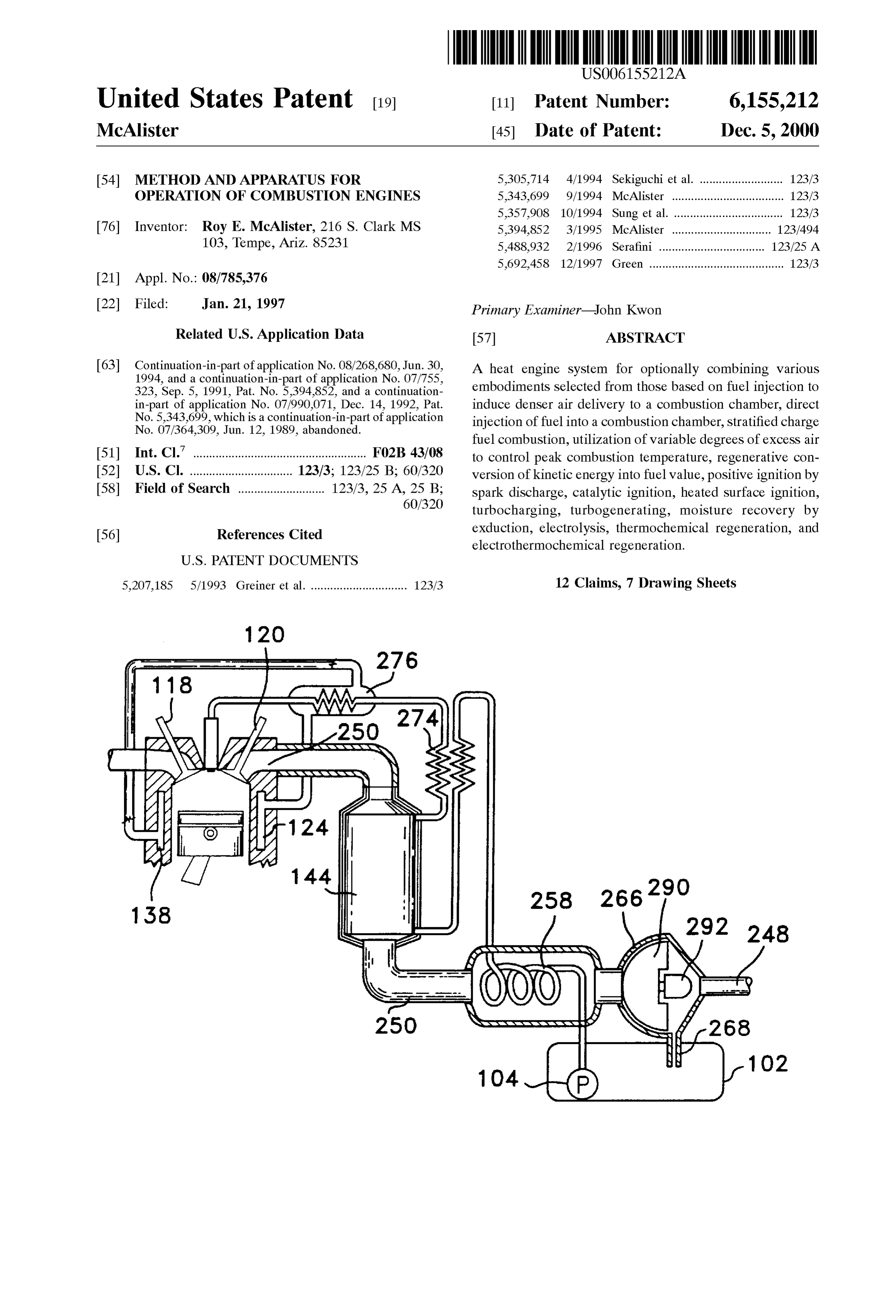
These and other objects of the present invention will natural gas, gasoline, or fuel alcohol feedstocks. This pro become more apparent during the course of the following cess is illustrated in FIGS. 1, 4, 7, 8, and 10. In FIG. 1, heat detailed description and appended claims. transfer 10 is Schematically depicted as energy vectors My invention may be best understood with reference to crossing each other. The width of each energy vector (arrow) the accompanying drawings, wherein an illustrative embodi generally depicts the magnitude of energy that is represented ment is shown. as heat, mechanical or chemical potential energy. The 15 chemical potential energy of incoming fuel and any other
BRIEF DESCRIPTION OF THE DRAWINGS
chemical feed Stock to be used in the engine is shown as
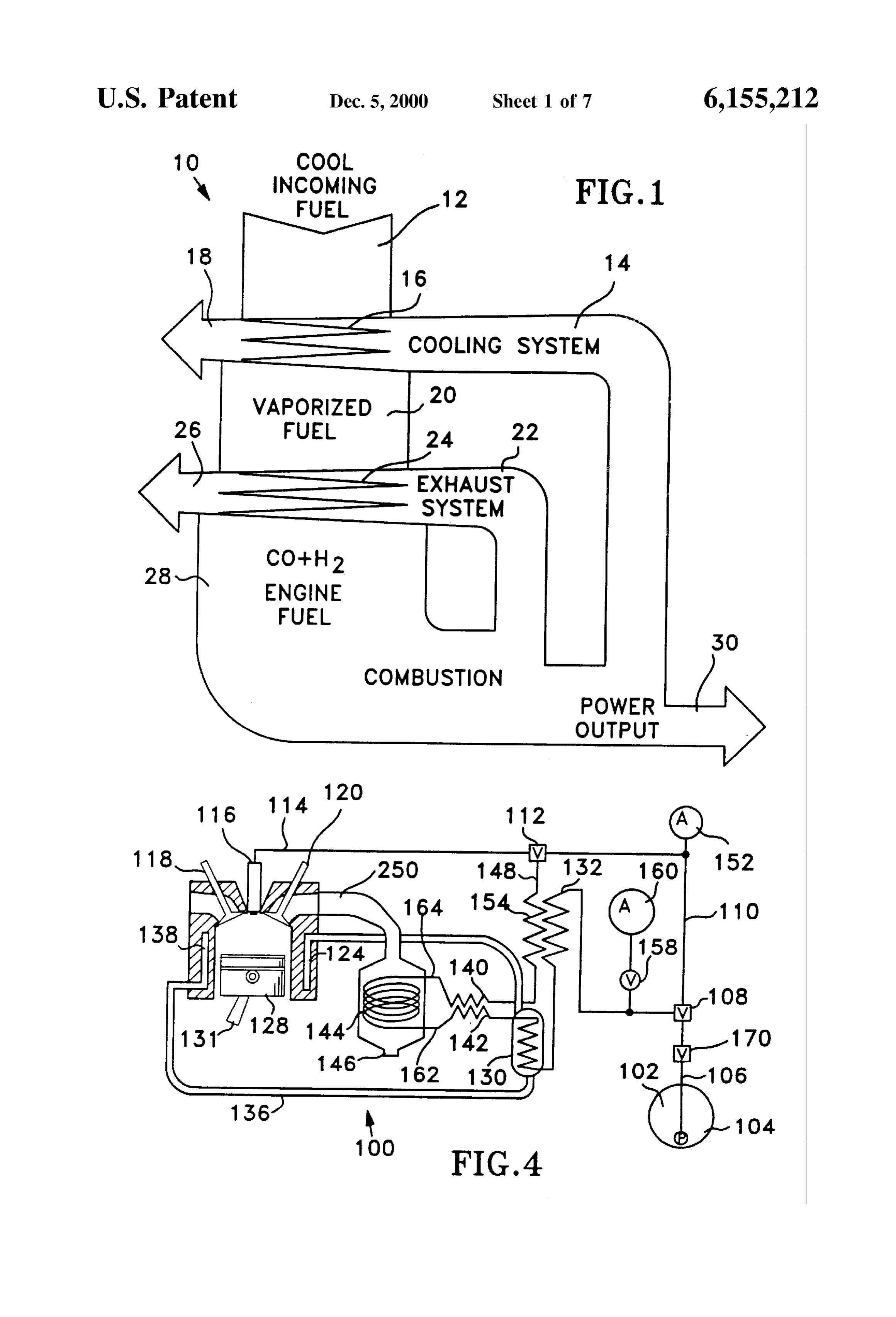
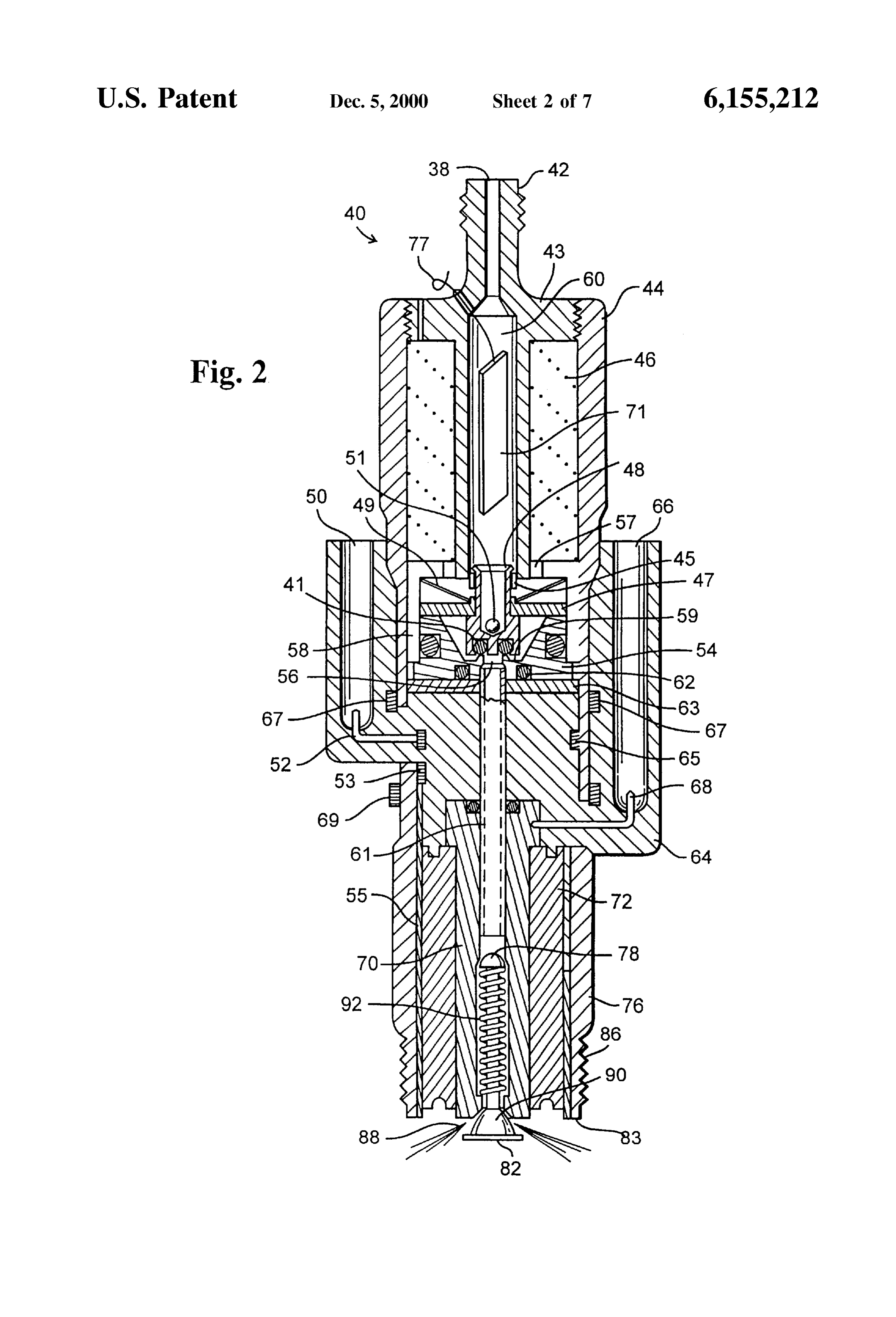
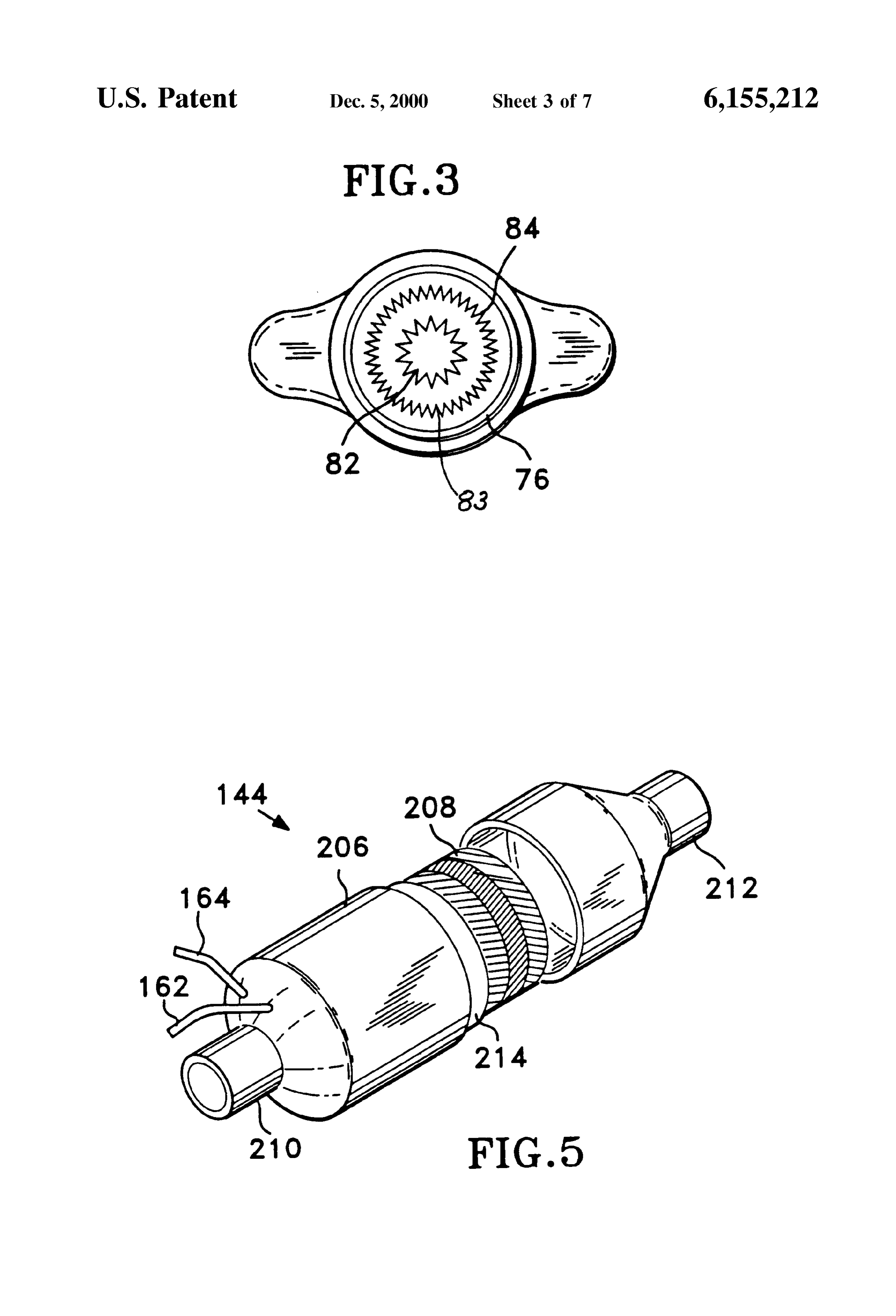
FIG. 1 is a Schematic illustration showing thermodynamic arrow 12. Cooling System heat is shown as arrow 14 which processes of the invention. is reduced in magnitude as shown by arrow 18 as a result of FIG. 2 is a longitudinal sectional view of a device heat transfer to incoming fuel at 16. Heated incoming fuel is constructed in accordance with the principles of the present increased in energy by the heat transfer as shown by arrow invention for directly injecting and igniting fuel in the 20. Heat from exhaust gases Is transferred to fuel 20 at 24 combustion chamber of an engine. as shown to reduce the energy of the exhaust gases from 22 FIG. 3 is an end view of the device of FIG. 2 showing the to 26 and increase the energy of the fuel to 28 by temperature location of ignition electrodes. 25 increases and creation of hydrogen and carbon monoxide as FIG. 4 is a Schematic circuit diagram of the invention shown in Tables 1 and 2. The engine-fuel 28 is burned in the showing a Sectional view of a representative combustion engine to produce motive power 30 and Supplies of waste chamber, a cooling System, an exhaust System, fuel Storage, heat 14 and 22.
fuel preSSurization, a cooling System, waste heat recovery Representative temperatures of the processes shown in eXchangers, an exhaust heat recovery exchanger, and deliv FIG. 1 are 21° C. (70°F) at 12; 93° C. (200°F) at 20, 260° ery of engine-fuel to the combustion chamber. C. (500°F) at 28; 4.09° C. (800°F) at 22; 107° C. (225°F) FIG. 5 is a perspective view of apparatus for recovering at 26; 115° C. (240°F) at 14; 38° F (100°F) at 18. These exhaust heat to be used to drive endothermic reactions temperatures vary depending upon the compression ratio of between fuel and an oxygen donor. 35 and mode of operation of the engine involved in the appli FIG. 6 is a schematic view of details of a preferred heat cation.
eXchanger tube-fin fabrication technique utilized in accor It is preferred to provide heat eXchange between hot dance with the principles of the present invention. engine-fuel at 28 and preheated fuel 20 in instances that FIG. 7 is a schematic view of one embodiment of an 40 large engines using appreciable amounts of fuel are apparatus utilized in accordance with the principles of the involved. Depending upon the degree of heat-transfer present invention for recovering energy and waste water desired, this reduces the temperature of engine-fuel to Some from the exhaust Stream of an internal combustion engine thing approaching the temperature of the engine cooling constructed in accordance with the principles of the present System and enables a much lower cost construction for the invention. 45 fuel delivery components because thermal degradation fac FIG. 8 shows a schematic view of another embodiment of tors are reduced. High flame Speeds, wide combustible an apparatus for recovering energy and waste water from the limits, high thermal efficiencies, elimination of particulates, exhaust Stream of an internal combustion engine. extremely low carbon monoxide and no unburned hydro FIG. 9 shows a longitudinal sectional view of a device 50 carbons characterize engine-fuel combustion results with the invention. These basic advantages are preferably facilitated constructed in accordance with the principles of the present by the use of invention for instrumenting engine processes including device 40 asa combination fuel-injection and Spark-ignition shown in FIGS. 2 and 9 to introduce the injecting and igniting fuel in the combustion chamber of a engine-fuel directly into the combustion chambers of inter combustion engine.
55 nal combustion engines. Embodiment 40 is provided with
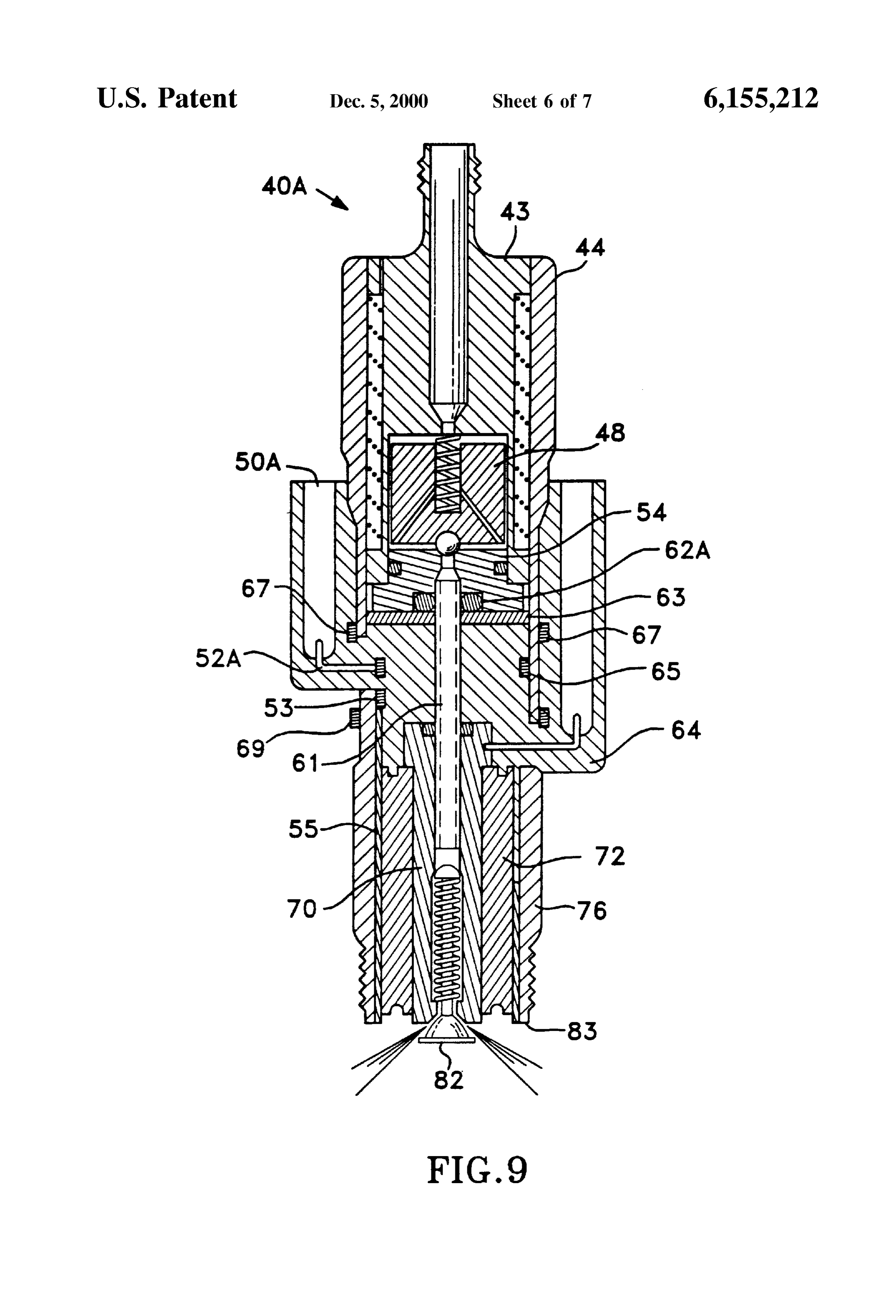
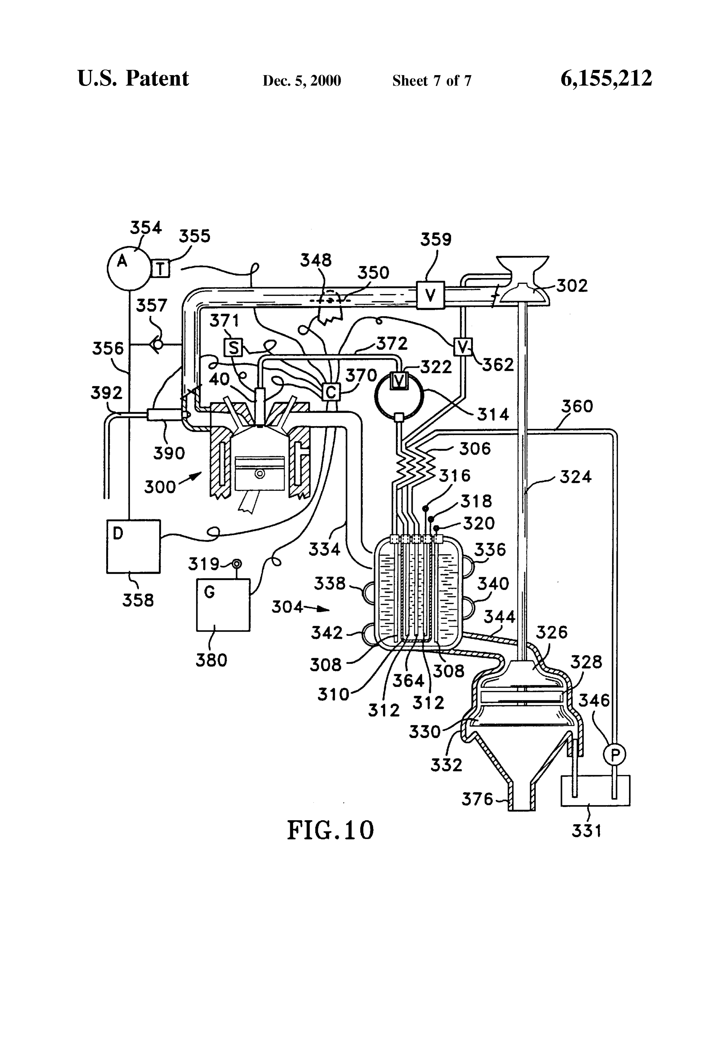
FIG. 10 shows a schematic view of a combustion engine the same thread and reach 86 as Spark plugs for the engine along with control Systems for power production, energy recovery, power assisting, and related operations in accor Served by the invention. In instances that the invention is applied to Diesel engines, the design at 86 duplicates the dance with the principles of the present invention for pro configuration of the conventional fuel injector in the Zone ducing hydrogen by electrolyzing water and other hydrog 60 that provides a Seal to the combustion chamber. enous feedstockS using any of a variety of electrical Sources AS shown in FIG. 2, pressurized engine-fuel enters and using the hydrogen as a Stratified-charge fuel. embodiment 40 at 38 through fitting 42 and is prevented DESCRIPTION OF THE PREFERRED from entering the combustion chamber as fuel Spray 83 until EMBODIMENTS 65 just before pressure increases are needed for the power cycle Waste heat (normally rejected through the cooling, in the combustion chamber. It is preferred to utilize an exhaust, and braking Systems) is used to Supply endothermic inertia disk 47 to Strike a valve-Seal component for quick
Page 13
opening to flow passage 61. Alternate methods of applying in applications where Substantial of water contamination is force to accelerate 47 include hydraulic, pneumatic, elec expected. This provision prevents wet gasoline, pipeline troStatic and piezoelectric forces but the preferred method is natural gas, and other fuels that precipitate condensates from by electromagnetism. Fitting 42 at the entry of the filter well being a problem in multifuel engine applications. is part of Solenoid body 43 within ferromagnetic housing 44. High Voltage is carried by compression Spring 92 through At the proper time, fuel is allowed to pass Solenoid poppet the wire bar shown to points 82. Spark plasma is developed assembly 48 (including integral ring 45, sliding disk 47, and across the gap between 82 and 83 as fuel 98 is sprayed into Seal 41) which is actuated against conical compression air in the gap shown for fuel ignition. Entering fuel is ionized Spring 49 by an electromagnetic force resulting from the and initiates combustion upon penetration of combustion flow of direct electrical current in winding 46. Fuel control chamber air. FIG. 3 shows the end view of the gap and spark Valve 48 is extremely fast acting against high fuel pressures points 82 and 83.
up to 10,000 PSI and can controllably-provide interrupted Poppet 90 is normally at rest against the seat of nozzle 70. bursts of approximately one millisecond duration. Poppet Moveable element 90 may be formed in any suitable shape assembly 48 is forced away from the orifice in seat 54 which 15 as may the valve Seat in 70 to produce the desired Spray is preferably a dense injection molded ceramic as shown for pattern 88 for the particular combustion chamber that the purposes of electrical isolation of metallic components in invention serves. It is the object of spray pattern 88 to valve 48 from high voltage in nozzle assembly 70. Non produce a great degree of air utilization in combustion magnetic gap ring 57 is preferably brazed in between reactions while minimizing oxides of nitrogen, unburned ferromagnetic components 43 and 58 as shown to cause hydrocarbons, carbon monoxide, and heat losses from com densification of the magnetic flux in linear armature 47 when bustion products after ignition.
it is actuated. When current flows through insulated coil 46, In application on Smaller engines, it is often most Suitable armature disk 47 accelerates rapidly and is centered by to provide a large included angle for a concave conical Seat conical Spring 49 as it closes the gap with electromagnet 43, 25 against 90 for use with a convex conical poppet 90 of 44, 46, and 58 and then Strikes the flange ring 45 of poppet Slightly Smaller included angle. This cone within a cone or assembly 48 which causes 48 to be suddenly lifted from seat “cone-cone' check poppet and Seat arrangement results in 54 to allow fuel to flow through numerous cross holes 51 considerably larger Surface to Volume ratioS for fuel entering past elastomeric Seal 41 which is preferably an O-ring as the combustion chamber than from any number of orifices shown. Fuel then flows through valve seat 54 and into which are typical to prior art injectors. Fuel entering the conduit 61 of a Suitable insulator tube and to Spray nozzle combustion chamber is Squeezed into a thin coniform layer 70. This extremely fast fluid valving embodiment accom by the action of Spring 92 and dynamic forces of air plishes rapid fuel flow past 90 and complete open, flow, and compression against the air-Side of poppet 90. Fuel com close valve cycles of about 1 millisecond bursts allow 35 bustion is extremely fast because of the large Surface to adaptive control of the combustion chamber temperature and Volume spray that is presented.
preSSure conditions in response to Signals from 52, 53, 55, The angle chosen for concave conical Seat against 90 is 62, 63 and 69 along with engine acceleration detection to usually optimized for the purpose of directing the conical adaptively meet performance and emissions abatement fuel Spray elements along the longest possible path before requirements. 40 interSecting a Surface of the combustion chamber. Ignition
Positive Seals Such as O-ringS 62 are used as shown to Seal occurs at the beginning of fuel entry into the combustion the fluid delivery path against leakage as shown. Insulator chamber and continues throughout the time of fuel now into materials 64 and 72 isolate lead 52 which is connected to the combustion chamber. This provides the greatest air preSSure Sensor 65 and high Voltage lead 68 which is 45 utilization and the longest burning time for controlled connected to electrode Spray nozzle 70. It is preferred to use temperature fuel combustion before approaching a quench injection molded thermoplastic for insulator body 64. Insu Zone of the combustion chamber. My invention provides an lator body 72 is preferably a glazed porcelain Similar to included angle of entry and variable gap between the Seat of Spark plug porcelain. 70 and 90 as a function of fuel pressure and viscosity. At Spring 92 urges the check valve head of wire bar 78 50 maximum torque production, high-speed conditions the closed as shown and 90 closed against the valve seat in 70 amount of fuel delivery is much larger and occurs during a to cause the fuel to be sprayed into the combustion chamber greater number of degrees of crank-shaft rotation. My inven as thin sprays of finely atomized fuel 88. This helps the tion provides optimized air utilization for different flame combustion to be rapid and complete upon reaching the 55 Speeds by providing an included angle for the fuel cone that oxidant following ignition. High Voltage for ignition is aims the entering rays of injected fuel at the Outer rim of the delivered by a Suitable Spark plug wire and terminal 68 in piston during the highest fuel flow rate of the intended duty high voltage well 66. Connection 68 delivers the high cycle.
Voltage to conductive nozzle assembly 70. For optimizing the fuel pattern for hydrogen or engine Water which is found as a contaminant in many fuels 60 fuels produced by reactions such as those in Table 3, the causes difficulties ranging from corrosion to freezing and included angle is large and the fuel is aimed at the piston rim blockage of fuel delivery. Electrode 71 is provided to at near top dead center. For slower burning natural gas or electrolyze water that reaches filter well 60. Electric current petrol fuels the included angle is Smaller and the fuel is is delivered by insulated lead 77 to 71 which is preferably a 65 aimed at a piston-rim location Somewhat after top dead formed as a thin walled cylinder with occasional beads of center. The opportunity is provided to optimize power dielectric insulators Separating it from the inside walls of 60 production for Start-up conditions in which a conventional
Page 14
fuel Such as natural gas, gasoline or Diesel fuel is burned and ignition without additional Spark discharge. Whisker dimen then after production of engine-fuel to have extremely Sions Suitable for the ignition process include 0.13 mm advantageous operation including production of more power (0.005 inch) to 2.29 mm (0.090 inch) diameter and lengths and better economy than with conventional fuel injectors. It from 0.51 to 6.35 mm (0.020 to 0.250 inches) depending is preferred to form poppet 88 from sheet or tube material upon the configuration of the combustion chamber of the and to provide highly angular points on the lower skirt as engine being served. Suitable materials for tips 82 and 83 shown for the purpose of reducing the discharge Voltage and include ferrous alloys such as 5 to 6% aluminum, 20 to 25% temperature during plasma generation. It is preferred to form chromium, balance iron; Silicon carbide, molybdenum sili electrode skirt 83 with highly angular points, as shown, for con compounds, cobalt Super-alloys, and nickel Super the same purpose. Alternate geometries of poppet 90 and the alloys.
form for the valve seat in 70 that are particularly suitable to In many applications it is desired to reduce Spark energy, combustion chambers of larger displacement engines is a minimize the use of Spark ignition, or to provide ignition spherical form in which the spherical surface of 90 contacts without the aid of Spark generation equipment. Reasons a concavo-spherical Seat in 70 of Somewhat larger radius. 15 include avoidance of Spark-Sourced oxides of nitrogen, This Sphere within a sphere or "sphere-sphere' check poppet radio interference, and Spark erosion of ignition compo and Seat arrangement results in a fuel Spray cone 88 that nents. This is accomplished by the use of catalytic coatings tends to provide increased Surface to Volume and greater air on the Surfaces of the valve seat of 70,90, 82 or 83. Suitable utilization than the cone-cone arrangement described previ catalysts include platinum black, nickel black, platinum, ously. In light-weight engines with high piston Speeds, Such palladium, osmium, iridium, nickel, nickel oxide, and inter as racing engines, it is preferred to maximize the flame Speed metallics of transition metals. Such as Vanadium-copper-zinc. by forcing production of an even greater degree of fuel It is advantageous to generate hydrogen-as provided in Surface to Volume ratio by providing a convex-Spherical Seat Equations 1-14 for purposes of increasing the thermal in 70 and a corresponding convex-Spherical Surface of 90. 25 efficiency and for cleanly starting the engine on engine-fuel In order to achieve Satisfactory fuel penetration into the or torching other fuel-air mixtures without Spark or with compressed air mass of larger combustion chambers it is greatly reduced Spark energy. Engine-fuel is particularly advantageous to provide channels (not detailed) in the conducive to reducing oxides of nitrogen because the energy Surface of 90 and 82 and/or in the Surface of the seat in 70, requirement for Spark ignition is only 0.02 mWS compared and for Specialization of the fuel Spray pattern 88. These to 0.29 mWs for methane and 0.24 mWs for gasoline. channels carry greater fuel flow than the areas between the Engine-fuel ignition requires less than 10% of the plasma channels and provide greater fuel penetration than from energy needed for gasoline and other hydrocarbons. This areas between the channels. Helical and other patterns of greatly reduces oxides of nitrogen formation at the begin channels that provide acceleration of the fuel at angles with 35 ning of combustion and is followed by limitation of maxi the shortest distance of travel from the orifice in nozzle 70 mum combustion temperature by control of the rate of fuel to the combustion chamber, cause rotation of component 90 addition and timing of injection and Ignition events to which is advantageous in polishing Seats 90 and 70 to keep optimize power production, fuel economy, engine them clean and uniform. Smoothness, etc., while minimizing oxides of nitrogen. These various cone-cone, Sphere-sphere, Sphere-cone, 40 Embodiment 40 of FIG. 2 and controller 370 enable many cone-sphere, and channel geometries provide important new modes of operation. Illustratively, a cold engine can be improvements over the prior art. Prior-art Diesel fuel injec Started on hydrogen as a Stratified charge for cleaning the tors and the injectors anticipated by U.S. Pat. Nos. 1,401, ambient air while providing greatest fuel economy, then 612; 3,173,409, 3,830,204; 3,094,974; 3,316,650 and 4,967, 45 Switched to operation of 40 as a Spark Source for ignition of 708 utilize sprays of fuel from one or more individual holes a conventional homogeneous charge fuel Such as gasoline to Spray fuel into air masses within the combustion chamber, after the exhaust catalysts are heated, and then to Switch mix with this air and then travel into a Spark gap at a critical operation on a combination of Stratified charge fuel 88 that time that the mixture is spark ignitable. Embodiments of the 50 is injected from 40 and ignited by 82 and 83 to penetrate present invention deliver fuel in a conical form having much with a multitude of burning rays into air-fuel mixtures that higher Surface to Volume ratio and does So in a pattern that are too lean to be ignited by a single Spark Source. assures completion of combustion events before the fuel For clean Starting on conventional fuels, tips 82 and 83 reaches quench Zones within the combustion chamber. may be coated with nickel oxide, cobalt oxide, Vanadium These various embodiments answer the need to optimize air 55 oxide or similarly effective materials to catalyze combustion utilization requirements in Virtually any combustion cham of hydrocarbons by increasing the rate of carbon monoxide ber design without resorting to efficiency-Sacrificing air formation in oxygen-deficient Zones within an overall Swirl and/or intake-air throttling techniques. oxygen-rich reaction. By catalyzing early formation of car My invention is applicable to large engines having com bon monoxide in the Zone around tips 82 and 83, the overall bustion chamber diameters of 12" or more and to Small 60 combustion reaction proceeds quickly into exceSS air to combustion chambers of the size that is Suitable for model produce carbon dioxide. Smoke particle formation is virtu airplane use. It is preferred to use ignition devices that are ally eliminated.
tapered to a point or whiskers that are pointed to decrease the In instances where the engine must Start and develop Spark discharge Voltage requirements on Start-up and in 65 emergency power without failure or hesitation, it is preferred Some engines to remain at Sufficiently elevated temperatures to Start with Spark plasma in the gap between 82 and 83 and between fuel introduction periods to assure hot-Surface to run with application of the plasma ignition until Satisfac
Page 15
tory power development is indicated. This assures rapid ous fuels including engine-fuel. AS shown, hydrogen which Starting and heating of 82 and 83 to ignition temperatures. characterizes engine-fuel combustion provides more than Applications Such as emergency power for hospitals, 7.5 times higher a flame Speed than more inert fuel Selec computers, and chemical processes are examples of Such tions. This enables much later injection and ignition of assured applications of the invention. In leSS critical appli engine-fuel than conventional hydrocarbon fuels and results cations it is preferred to plate points 82 and 83 with coatings in greatly improved brake mean effective preSSure per BTU Such as nickel or platinum-group alloys. In more requiring of fuel value by not incurring back work during slow applications it is preferred to manufacture 82 and 83 from burning pressure rise in the compression cycle of the engine Such materials for long-life Spark-ignition and for causing operation.
catalytic along with hot-Surface ignition. Combinations of Engine-fuel combustion is characterized as an extremely Spark, catalytic and hot-Surface ignition provided by these fast combustion proceSS and the degree of heat loSS by embodiments make the invention Suitable for engines of radiation to combustion-chamber Surfaces is much less in every size, piston Speed and application. Depending upon comparisons to conventional fuels. The present invention the “cone-sphere' design Selected, ignition occurs by fuel air 15 facilitates injecting and igniting engine-fuel just after top contact with catalytic or hot surface effects on 82 and 83 or dead center (TDC) to provide much quieter operation due to passage of low-temperature Spark-plasma energy because piston knock and Vibration due to untimely ignition through the alternate layers of air, exceSS-air-fuel Zones, during the compression cycle are eliminated by the inven fuel-rich Zones, exceSS-air-fuel Zones, and air. The greatest tion. Converted engines runs cooler, Smoother, quieter and flame Speed occurs in the Surfaces of the fuel-rich Zones. more efficiently than with conventional fuel conditioning Even at the highest piston Speeds this creates a fuel-rich, and delivery Systems.
higher-speed combustion-process driver within exceSS air FIG. 4 shows the method of the invention in a schematic Zones that assures completion of combustion events in circuit of thermochemical operations. Heat engine 100 slower combustion rate areas. 25 which may be any heat engine Such as a gas turbine; It is preferred to use a spark generator 371 of FIG. 10 that rotary-combustion; external-combustion Stirling-type reverse polarity with every Spark to reduce Spark erosion on engines including EricSSon and Schmidt, or an internal 82 and to eliminate high-voltage electrolysis of insulator 64. combustion engine as depicted with any Suitable expander Spark Voltage generator 371 may be of any Suitable design Such as piston 128 and rod assembly 131 as shown along for delivering alternating Spark current to the gap between with intake valve 118 and exhaust valve 120. Fuel is stored 82 and 83 as shown. This greatly improves ignition effi at 102. The fuel may be any suitable selection such as ciency and the life of spark-injector 40. Prior art devices compressed natural gas, a Suitable fuel alcohol, liquid natu depend upon Swirl of the air in the combustion chamber to ral gas, ammonia, gasoline, or Diesel fuel. Liquid fuels deflect fuel Sprays into helical paths in order to prevent 35 Stored at ambient pressure are preferably pressurized by penetration to quench Zones. Creating Swirl of air in the pump 104 to required fuel injection preSSures, which ranges combustion chamber is produced by impedance to air entry. depending upon fuel Viscosity, Surface tension, molecular This reduces the mechanical efficiency of the engine by weight, and carbon to hydrogen mass ratio, from about 100 incurring reduced pressure over the piston compared to the 40 to 1,500 psi above the compression pressure of the engine. preSSure under the piston. More mechanical work must be At Start-up conditions with positive-displacement done to overcome the manifold-vacuum condition than if engines, cold fuel is delivered to three-way valve 108 and there was no impedance to the air entry. Prior-art approaches directed to the engine through line 110, three-way valve 112, depend upon variable air throttling in all practical modes of line 114, and fuel injector 116. Fuel is sprayed into and operation to produce homogeneous mixtures of fuel and air 45 ignited within all combustion chambers that are about 1% to at all levels of power production. In order to be Spark 70% into power (expansion) cycles. Rapid heating of the air ignitable the air had to be throttled so the fuel could be and power delivery results. The engine is Started without a reduced from highest power ratings to lowest power ratings. Starter motor or started much more rapidly if a starter motor This type of operation greatly reduces part-load efficiency is utilized to assure development of oil preSSure. After the by increasing the preSSure difference through which the 50 engine is started, injection and ignition timing are advanced piston must operate during intake conditions. to provide optimum conditions. My invention provides multiple Sparks and penetration of It is preferred to use an electric pump in conjunction with the combustion chamber with a pattern of burning fuel rays the engine's mechanical pump for pressurization of liquid when necessary with varying turbulence and to assure 55 fuels. In instances that the bearing designs require preSSur ignition regardless of fuel Selections with widely varying ization of oil to the crank and cam Shaft bearings before Viscosity, density, and heat-release characteristics along with Start-up, it is preferred to provide a Safety interlock to widely varying air/fuel ratioS. My invention allows unim prevent fuel injection until oil pressurization by a Suitable peded air entry into the combustion chambers at all power hand or electric pump has been accomplished. levels for maximum mechanical and Volumetric efficiencies. 60 Direct-injection with Spark-ignition starting is an impor This provides more power, Smoother operation without tant improvement over prior-art methods of Starting an “dead spots”, and a greater range of acceptable Speed-torque engine. It results in much reduced package weight, initial conditions. It is preferred to operate at overall fuel-air ratioS cost Savings, and elimination of Starter-System maintenance ranging from far-exceSS air at low-power Settings to exceSS 65 expense. This quick Starting System allows the engine to be air at higher-power Settings. Table 2 shows the limits of Stopped at Stop Signs and instantly restarted to power the flammability, flame Speed, and heat of combustion of Vari vehicle when needed. This eliminates waste of fuel and
Page 16
production of pollutants at conditions when power is not the combination fuel-injector and Spark-ignitor 40 shown in needed. It is preferred to use a conventional electronic FIGS. 2 and 3.
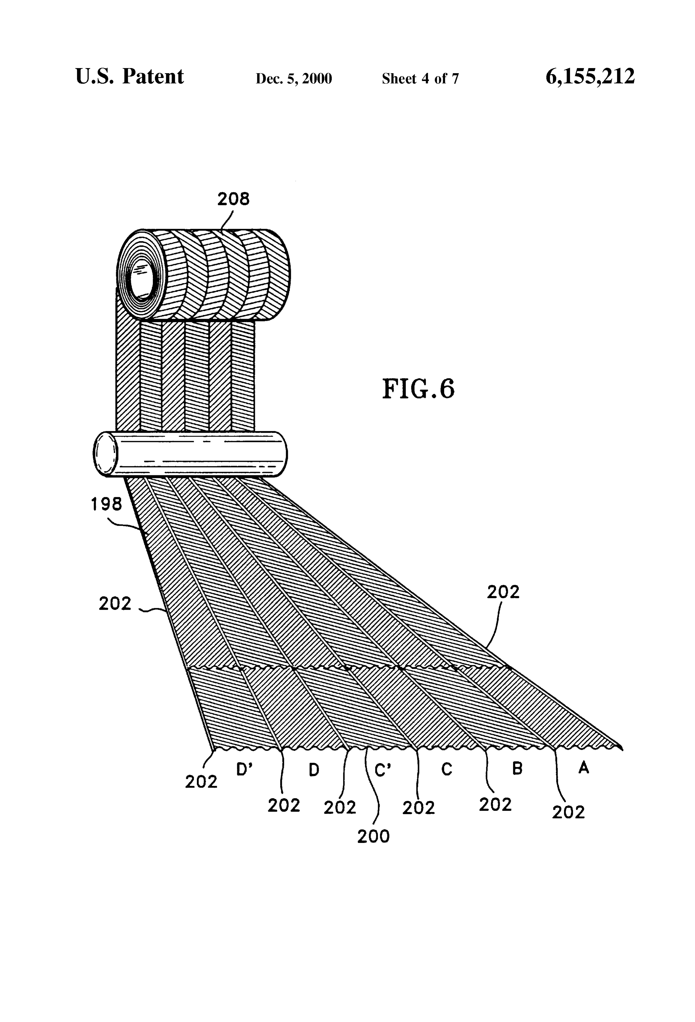
microprocessor with memory for monitoring, Starting, and Details of the preferred embodiment for thermochemical optimizing the engine. Piston locations within combustion converter 144 are shown in FIGS. 5 and 6. Recovery of chambers are stored at shut down and recalled for the waste heat from the engine is provided by passing hot start-up routine. A suitable microprocessor 370 of FIG. 10 exhaust gases into inlet 210 of canister 206. Heat eXchange facilitates Safe operation by instantaneous monitoring of oil from hot exhaust gases heats the feed StockS delivered preSSure, temperature, vibration, and other vital instrumen through tube 162. Thermochemically converted engine-fuel tation to provide emergency shut-down if the engine has no leaves reactor 144 through tube 164 and is preferably cooled lubricating oil or if other malfunctions occur. by regenerative beat eXchange to feed Stock fluids in heat Compressed gas fuels Stored in 102 are pressure reduced exchangers 140/142 and 132/154 as shown in FIG. 4. from the Storage preSSure and regulated at the desired Heat eXchange and catalytic conversion of feed Stock pressure of delivery. Fuel injection through 116 is preferably fluids within 206 are provided by flat tube coil 208. Tube coil at Substantially top dead center conditions until the Storage 15 208 is preferably made from two strips of metal that are tank 102 is nearly depleted and fuel pressure is reduced formed to provide extremely high Surface areas for heat below the desired delivery pressure. My invention provides transfer and catalytic actions upon mixtures or Solutions of the Steps of injecting the fuel Substantially at top dead center feed stock fluids. One such embodiment 200 for the strip conditions of the combustion chambers until the Storage stock is shown in FIG. 6. Strip 200 is formed to have preSSure is reduced due to depletion of the Storage inventory corrugated, knurled, herringbone, or otherwise circuitous and then injecting the fuel progressively earlier in the surfaces as shown. It is continuously bonded to sheet 198 compression period and then progressively into the intake along seams 202 as shown. Sheet 198 may be formed like condition of the combustion chambers to facilitate greater 200 or provided as an essentially Smooth sheet. A particu range from the fuel Storage System by providing an opti 25 larly high Surface to Volume catalytic heat eXchanger is mized way to utilize the last portions of stored fuel. After formed from sheets 198 and 200 in which each sheet is injecting fuel and monitoring combustion chamber condi corrugated to form adjacent herringbone designs in the areas tions as indicated by instrumentation 62A, 63, or 65 in between seams 202 when assembled as shown. The herring spark-injector 40A of FIG. 9, timing of fuel injection and bone corrugations of each sheet are opposite the other sheet. ignition are optimized for the Subsequent injection and This provides parallel internal tube-ways between Seams ignition events according to the fuel Storage pressure avail 202 that have circuitous internal channels to force turbulent able. AS the fuel Storage pressure is depleted, the timing of flow of reactants at all portions of fluid progreSS through the injection progresses from near top dead center towards reactor and turbulent flow of exhaust gases through the bottom dead center and finally into the intake period of the 35 corrugated Spaces that are provided between formed or engine. rolled layers of the assembly.
After the engine has warmed up and the temperature at Tube ways are manifolded to provide the desired circuits thermochemical converter 144 has reached about 500 F., through reactor 144. It is preferred to have counter-current valve 108 shuttles to direct fuel to heat exchanger circuit 40 heat eXchanges in which the coolest fluid entering the 154/132 as shown. The engine continues to operate on fuel reactor receives heat from the coolest exhaust gases as Supplied by accumulator 152. Fuel and any other desired shown. Fluid nearing the exit of the, reactor receive heat oxygen donor (Such as air or the combinations listed in from the hottest exhaust gases. After manifolding the tube Tables 1 and 2) from tank 160 is pressurized by Suitable ways, the assembly is spiral wound on a tube and the pump 158 and heated in heat exchanger 130 by cooling fluid 45 assembly is encased in insulated canister 206. The Spiral delivered from cooling jacket 124 and returned to cooling wound assembly is shown in FIG. 5.
jacket 138 through conduit 136 as shown. Combinations of Heat additions through catalytic Surfaces are preferred to fuel from tank 102 and water or another oxygen donor from perform the desired reactions of Equations 1-11. The tank 160 are called “reactants”. Further heating of the 50 embodiment shown in FIGS. 5 and 6 provides high thermal reactants is accomplished by counter-current eXchange conductivity with catalytic functions. Sheet materials for between 140 and 142 with engine gas produced in thermo reactor 208 may be typical to those listed in Table 4. As chemical converter 144. shown, a wide variety of alloys and Surface coatings for iron, Final heating of the reactants and production of engine aluminum, and copper based sheet Structures are possible. gas results from catalytic processes in converter 144. Hot 55 The catalyst Selections may have further roles of Serving as exhaust gases 250 ranging in temperature from over 593 to bonding or Sealing agents in the catalytic heat eXchangers. 316° C. (1100°F. to 600°F) depending upon the duty cycle After forming, Seam welding, manifolding, and coiling, the are delivered to thermochemical converter 144 as shown. assembly may be furnace or induction brazed to bond Cooled exhaust gases pass through exhaust conduit 146. 60 contact areas inside the flat tubes and between layers of flat Cooled jacket fluid is returned to the engine through conduit tubes. This greatly strengthens the assembly. 136 for circulation through Suitable cooling passages 138 Sheet Strip Selections are first plated or hot-dip coated to and 124. Another heat rejecting circuit comprising an ordi uniform coating thicknesses by any Suitable production line nary radiator and thermostatic valve may be used in Series or technique and then roll-bonded or Seam-welded along the in parallel with the circuit of 130 and 136. Engine-gas is 65 Seam Zones 202. It is preferred to bond all areas of contact delivered to three-way valve 112 and directed to the engine between sheet 198 and 200 to arrest pressure stresses from through line 114 and fuel injector 116. It is preferred to use the fluids within the flat tubes. It is also anticipated that
Page 17
diffusion gradients of desired catalytic agents would be manifolding and a core for the Spiral assembly is provided produced by multiple platings or coatings followed by heat by joining the coil to a 76 mm dia., 4.75 wall (3" diameter, treatment. 0.187" wall) tube that is internally partitioned to provide Although Zinc and copper have been recorded in prior art desired series flow of vapors through A and B then parallel efforts to dehydrogenate alcohols, it is important to note that flow through C and C" followed by parallel flow through D the present invention uses catalytic alloys of Zinc and copper and D" as shown in FIG. 6. Exhaust gases pass into the or coatings containing Zinc and copper in Solid Solution to reactor from connections 210 to 212 to provide a modified provide heterogeneous dehydrogenation of alcohols, organic counter-current heat-exchanger, endothermic-reactor com Solutes, and water more or leSS Simultaneously. A Series of bination.
intermediate reactions are believed to be responsible for the Engine cooling jacket water at 82° C. to 121 C. (180° F. overall reactions as shown in Equations 1-11. A particularly to 250 F) may be circulated in an additional section of heat useful aid to the understanding of intermediate reactions is eXchanger 130 to provide Standardization of the engine gas found on pages 535 through 586 of the Second Edition of the temperature. In this instance, the cooling jacket water would Kirk-Othmer “Encyclopedia of Chemical Technology” and 15 be circulated from 124 to 138 through heat exchanger 130 as this reference is incorporated herein. shown in counter-current arrangement to flow of engine gas.
As noted in Table 4, the listed alloy sheet catalysts have exchanges alternate arrangement for providing desired heat considerable ductilities and allow cold working to form one assembly is to build heat exchangers 130 and 132/154 in turbulence-inducing patterns, Such as corrugations or jacket water circulation with thenmostatically-controlled engine crossed rows of emboSSments depending upon the hot engines with materials that from inlet 124 to 138. In emerging endurance Strength of the Selected sheet System at the temperatures of 260° C. (500 allow combustion-chamber wall F) and higher, it is preferred operating temperature chosen for the application. Sealing to provide Standardization of the engine-fuel temperature the lower sheet to the upper sheet is accomplished by with Split-phase heat-pipe heat eXchangers. Final heat Sink metallurgical joining along 2.29 mm (0.090") wide seams 25 ing to the vehicle frame, cogeneration heat requirements for 202 between 25.4 mm (1") wide channels 204. A suitable air conditioning, and further preheating of feedstock Sup sheet-stock thickness for strips 198 and 200 of the embodi plies of wet-fuel alcohols are contemplated. ment of FIG. 6 is 0.25 mm (0.010") with a corrugated PreSSurized engine-fuel from 104 or a Suitable regulator is channel depth of 0.38 to 1.52 mm (0.015" to 0.060"). This controlled by Solenoid-operated, three-way valves 108 and gives a very low clearance Volume within the assembled 112. Engine-fuel in heat eXchanger Section 154 is monitored reactor coil, for temperature and pressure conditions. Valve 112 is oper The inventory of engine-fuel is minimized by the low ated “OPEN” to allow flow from heat exchanger section 154 clearance Volume in all parts of the fuel conditioning System. to fuel injector 116 if the temperature and pressure are within To further assure Safety, pressure is monitored in lines 106, 35 preset limits. Valve 112 is “CLOSED” to flow from 154 but 110, 148, and 114. If the rate of pressure change exceeds a “OPEN” to flow from pump 104 and provides assured narrow preset value, pump 104 is Stopped and valve 170 is engine Start-up and operation with injection of liquid fuel closed to prevent entry of additional fuel to the fuel until desired temperatures and pressures are developed in conditioning System. Because heat eXchangers 130 and 144 40 section 154. During operation with liquid fuel, map “A” of are housed in water cooling or exhaust Systems, additional the fuel management System is used. During operation with fail-safe virtues are provided. If a leak in heat exchanger 130 gaseous engine-fuel map “B” is used. Operation between or 144 would occur pump 104 would shut down, normally maps A and B is electronically Switched in correspondence closed Solenoid valve 170 would close, and the Small to the operation of Solenoid valve 112. inventory of escaping fuel would be contained in water or in 45 Fuel entering the combustion chamber is ignited by Sparks the exhaust pipe where it could do no harm. Fuel pressures that pass through alternate layers of air-fuel-air and ignition of 680 atm. at 538°C. (10,000 psi at 1,000 F) are practical is assured regardless of the overall combustion chamber with catalyst sheets having yield strengths of 20,000 psi or inventory of air and fuel. Overall air to fuel ratios of 1,000 more because of the tightly coiled and bonded spiral assem to 1 are as assuredly ignited by the invention as are air to fuel bly. An additional aid in arrestment of stress is by transfer of 50 ratios of 15 to 1. The invention provides best fuel economy compressive preload from the outer containment by tubular and minimum emissions during cold-engine conditions with structure 206 as shown in FIG. 5 which is preferably direct-injection and Spark-ignition of liquid fuels. Later, constructed from Several wraps of thin Strip Stock to reduce after reaching the engine S designated operating heat losses and provide high Strength. 55 temperature, the invention provides useful recovery of It is preferred to thermally isolate coil 208 from canister engine waste heat by operating on gaseous fuels that pro 206 by refractory fiber sleeve 214. This provides an air duce considerably more energy upon combustion than the cooled containment cylinder 206 in which tensile loading feedstock liquid fuels. The invention facilitates these fuel occurs to produce compressive loading of coil 208. Use of 60 efficiency advantages without Sacrificing Specific power the insulator sleeve provides a space for 12 mm OD, 2.4 mm ratings of the engine in power-per-thermal-unit compari wall (%"OD, 0.095" wall) manifold tubing of stainless steel Sons. This is an extremely important aspect of the invention tubing which is also used to convey engine gas to heat because it is generally necessary to specify 30% to 150% eXchanger Section 130 and to fuel injectorS 116. In applica larger displacements and increased compression ratios (than tions where additional Safety considerations are warranted it 65 for carbureted gasoline fuels) when use of gaseous fuel is is preferred to clad tubing 106, 110, 148, and 114 with a contemplated. The larger engine requirement cascades into sheath of high-strength stainless steel such as 17-7 PH. Inlet application penalties including:
Page 18
1. Larger tires, Shock absorbers, Springs, Starter motors, The reactants in Equations 1-8 of Table 3, consisting of batteries, alternators, power assist units, transmissions, one or more alcohols, one or more Soluble organics, and and brakes for a greater curb weight in transportation water, are heated by exchange with exhaust gases to tem applications.
2. Greater requirements for iron, chromium, peratures ranging from 107 to 538 C. or 225 to 1,000 F. molybdenum, Vanadium, manganese, nickel, and petro Hot organic-compound vapors and Steam mixtures are leum reserves. More energy is required to mine, mill, passed through a catalyst to produce mixtures of carbon refine, alloy, cast, forge, machine, and build the larger monoxide and hydrogen. Equation 9 illustrates how natural engines. The greater demands upon finite reserves of gas or biomass methane is reacted with Steam to produce critical materials produce higher prices per pound and force inflation in the world's economy. hydrogen and carbon monoxide. Equations 10 and 11 typify In addition, the invention overcomes the difficult prob the reaction of gasoline and Diesel blends with a liquid lems of back-firing and hesitation, wherein hydrogen is containing oxygen to produce carbon monoxide and hydro inopportunely burned within the intake manifold of carbu gen upon endothermic reaction. These reactant blends would reted or manifold injected engines. This problem Stems from 15 also contain emulsifiers for long-term Storage purposes. The the fact that hydrogen will Support combustion in remark Vaporous product or engine-fuel is used in the combustion ably wide fuel-to-air ratioS and because flame Speeds in chamber as a Stratified-charge fuel and is Spark-ignited. hydrogen combustion are extremely high. The invention Heat-release potentials for complete burning of the prevents back-firing by eliminating any mixing of hydrogen engine-fuel constituents exceed the complete burning poten and air until the fuel-injection event within the combustion tials of the fuel feed stocks by 20% to 40%. Increases in chamber.
Production of engine-fuel from inexpensive fuel alcohols heat-release potentials are derived by exchange from engine and compressed or liquid natural gas is facilitated. Alonger waste heat to the endothermic reactions generally shown in range regime would use bio-Sourced methane and wet 25 Equations 1-14 of Table 3. Equally important is the oppor ethanol and methanol. The present invention thermochemi tunity to use wet fuels that are 30 to 50% less energy cally processes and utilizes feed Stocks that are less refined intensive in initial production than are the anhydrous and less expensive than gasoline or Diesel fuels including alcohols, phenol, or other organic-compound counterparts. natural gas, crude alcohols, and ammonia liquors as shown Another problem that the present invention overcomes in Tables 1-3. Considerable range and thermal efficiency concerns the ability to gain as much power per BTU or improvements are offered with Diesel and gasoline fuels. calorie of heat release from engine-fuel as gasoline produces Fuels. Such as natural gas, coal gas, acetone, methanol, in Spark-ignited engines. It is generally conceded that ethanol, propanol, propane, butane, ammonia, and butanol gaseous-fueled engines require considerably larger engine are attractive replacements for traditional petroleum fuels. 35 displacements than gasoline-fueled engine per unit of power The fuel alcohols and light paraffins are readily produced development. This is because previous attempts to use from coal, peat, oil shale, tar Sands, natural gas, Solid wastes, gaseous fuels have mixed the fuel with air during intake or freshly-grown biomass. Using Sewage- and garbage processes. Considerable breathing capacity and cycle energy Sourced hydrogen, methane, and fuel alcohols is facilitated 40 have been diverted to introducing the gaseous fuels into the and the invention allows petroleum to be used for making engine. In the present invention, the full breathing capacity more valuable polymers and petrochemicals.
A well-recognized and long-standing problem concerning of the engine is reserved for intake of exceSS Volumes of bio-fuels is the energy-intensive nature of producing fuel combustion air. Brake mean effective pressures (BMEPs) alcohols from coal or biomass. Water present in the coal or 45 are higher because: there are more molecules present in the biomass feed Stocks, along with Steam used in reactions with combustion chamber to do expansive work, with more air carbonaceous feed Stocks to gasify the feed StockS requires present, more fuel can be combusted to release more energy; considerable energy to reach proceSS reaction temperatures. and the pistons are not required to do work (against crank After generation of mixtures of hydrogen and carbon mon 50 case atmospheres) in comparison to manifold vacuum. oxide (water-gas) and catalytic Synthesis of fuel alcohols, Water requirements not met by using wet alcohols or other considerable additional energy often is required to remove combinations shown in Tables 2 and 3 may be supplied by water condensates and produce anhydrous fuel. condensation of water vapor from the exhaust gases of the Commercial production of methanol by the Oxyl process, heat engine employing the invention. Approximately one the action of fermentation enzymes, or destructive distilla 55 gallon of water is produced form each gallon of hydrog tion of lignin and cellulose could be considerably leSS enous fuel burned by a heat engine. Illustratively, one mole energy-intensive if the product could be used “wet” (130- to of octane (or gasoline) thermochemically regenerated with 190-proof) rather than “dry” (200-proof). My process and eight moles of water burns in air to produce Seventeen moles apparatus facilitates the advantageous usage of natural gas, of water. Only eight moles out of the seventeen needs to be
wet-fuel alcohols, water-Soluble or alcohol-Soluble organic recycled:
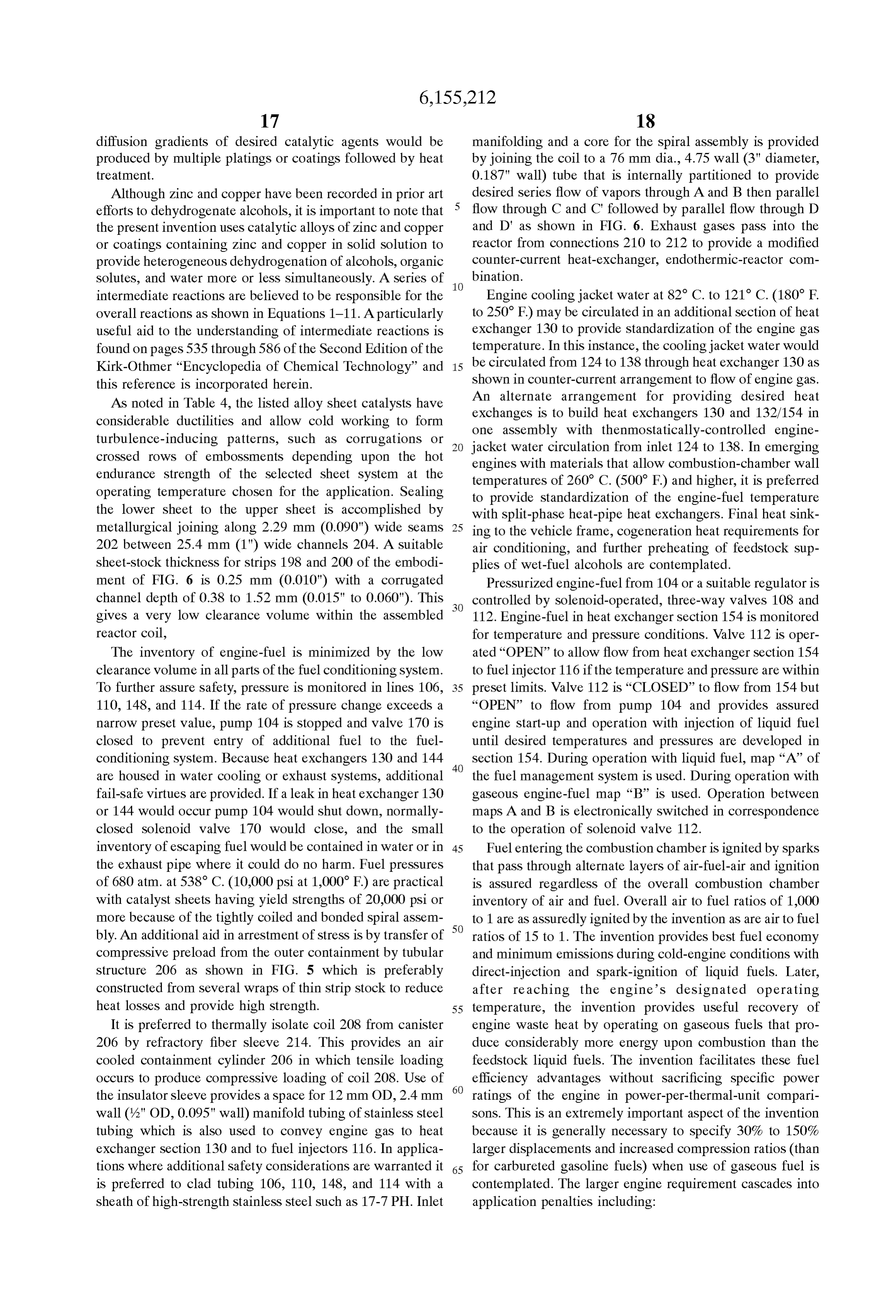
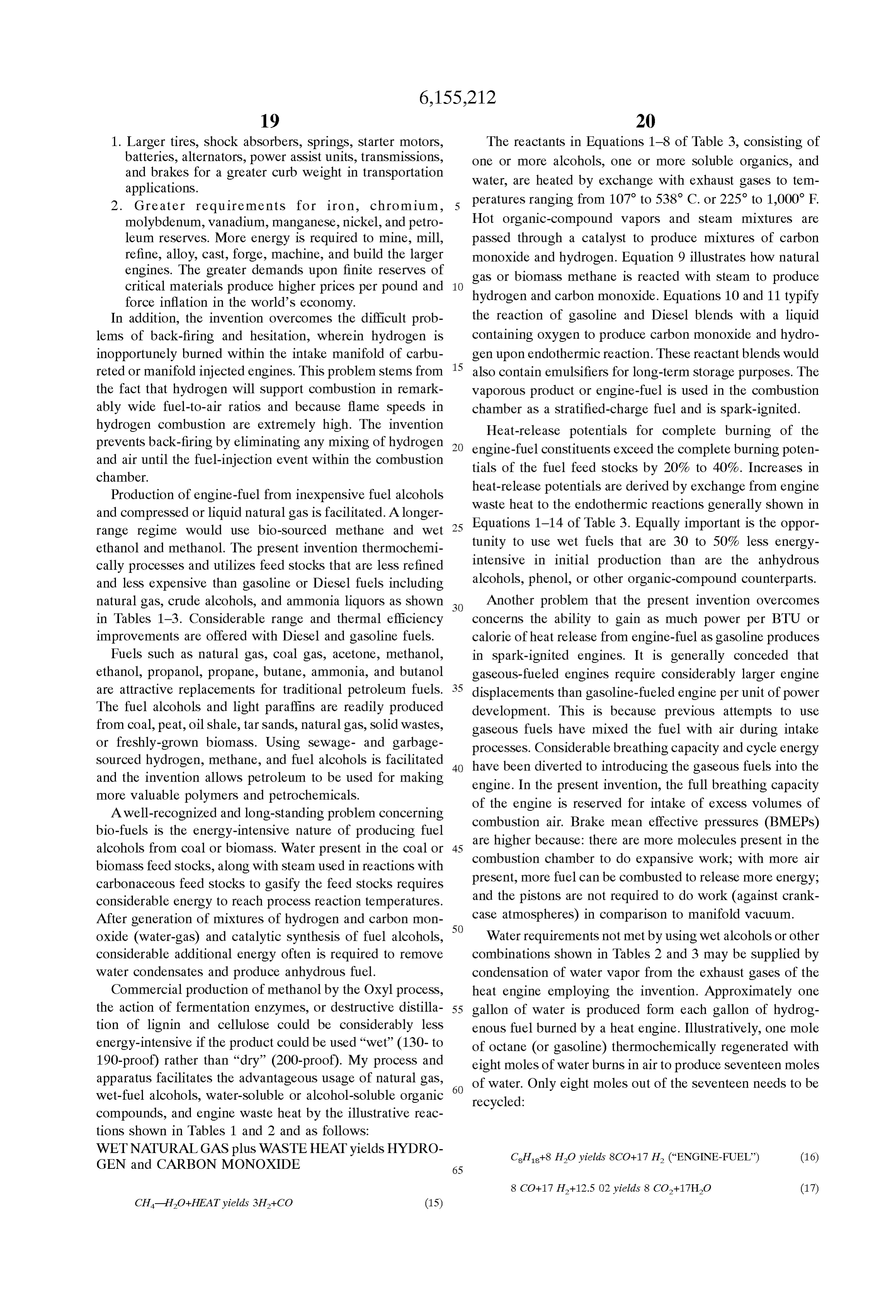
compounds, and engine waste heat by the illustrative reac tions shown in Tables 1 and 2 and as follows:
WET NATURAL.GAS plus WASTE HEAT yields HYDRO CH+8 HO yields 8CO+17 H., (“ENGINE-FUEL) (16) GEN and CARBON MONOXIDE 65
Page 19
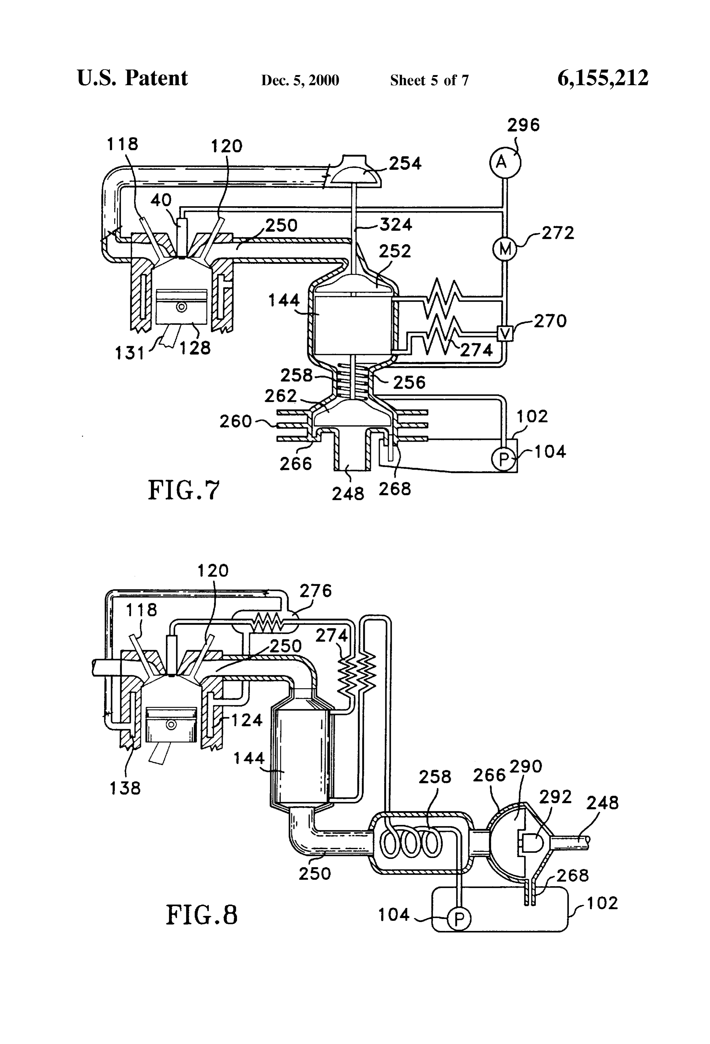
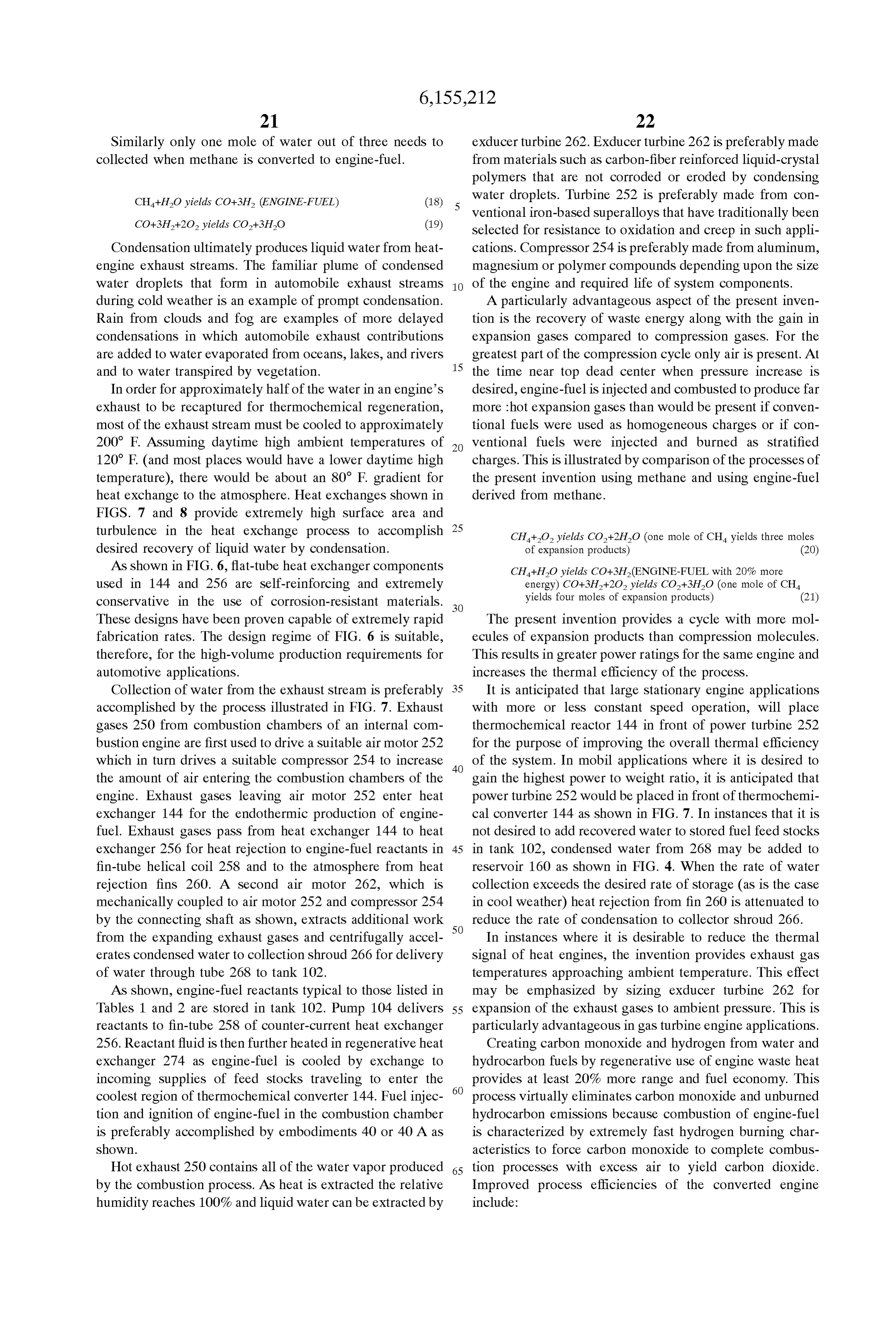
Similarly only one mole of water out of three needs to exducer turbine 262. Exducer turbine 262 is preferably made collected when methane is converted to engine-fuel. from materials. Such as carbon-fiber reinforced liquid-crystal polymers that are not corroded or eroded by condensing
CH+HO yields CO+3H, (ENGINE-FUEL) (18) water droplets. Turbine 252 is preferably made from con ventional iron-based Superalloys that have traditionally been (19) Selected for resistance to oxidation and creep in Such appli
Condensation ultimately produces liquid water from heat cations. Compressor 254 is preferably made from aluminum, engine exhaust streams. The familiar plume of condensed magnesium or polymer compounds depending upon the size water droplets that form in automobile exhaust Streams of the engine and required life of System components. during cold weather is an example of prompt condensation. A particularly advantageous aspect of the present inven Rain from clouds and fog are examples of more delayed tion is the recovery of waste energy along with the gain in condensations in which automobile exhaust contributions expansion gases compared to compression gases. For the are added to water evaporated from oceans, lakes, and rivers greatest part of the compression cycle only air is present. At and to water transpired by Vegetation. 15 the time near top dead center when pressure increase is
In order for approximately half of the water in an engine's desired, engine-fuel is injected and combusted to produce far exhaust to be recaptured for thermochemical regeneration, more hot expansion gases than would be present if conven most of the exhaust Stream must be cooled to approximately tional fuels were used as homogeneous charges or if con 200 F. Assuming daytime high ambient temperatures of ventional fuels were injected and burned as Stratified 120° F (and most places would have a lower daytime high charges. This is illustrated by comparison of the processes of temperature), there would be about an 80° F. gradient for the present invention using methane and using engine-fuel heat eXchange to the atmosphere. Heat eXchanges shown in derived from methane.
FIGS. 7 and 8 provide extremely high surface area and turbulence in the heat eXchange process to accomplish 25 CH+O, yields CO+2HO (one mole of CH yields three moles desired recovery of liquid water by condensation. of expansion products) (20) AS shown in FIG. 6, flat-tube heat eXchanger components CH+HO yields CO+3H,(ENGINE-FUEL with 20% more used in 144 and 256 are Self-reinforcing and extremely energy) CO+3H+2O, yields CO+3HO (one mole of CH conservative in the use of corrosion-resistant materials. yields four moles of expansion products) (21) These designs have been proven capable of extremely rapid The present invention provides a cycle with more mol fabrication rates. The design regime of FIG. 6 is suitable, ecules of expansion products than compression molecules. therefore, for the high-volume production requirements for This results in greater power ratings for the same engine and automotive applications. increases the thermal efficiency of the process. Collection of water from the exhaust stream is preferably 35 It is anticipated that large Stationary engine applications accomplished by the process illustrated in FIG. 7. Exhaust with more or leSS constant Speed operation, will place gases 250 from combustion chambers of an internal com thermochemical reactor 144 in front of power turbine 252 bustion engine are first used to drive a Suitable air motor 252 for the purpose of improving the overall thermal efficiency which in turn drives a Suitable compressor 254 to increase 40 of the System. In mobil applications where it is desired to the amount of air entering the combustion chambers of the gain the highest power to weight ratio, it is anticipated that engine. Exhaust gases leaving air motor 252 enter heat power turbine 252 would be placed in front of thermochemi eXchanger 144 for the endothermic production of engine cal converter 144 as shown in FIG. 7. In instances that it is fuel. Exhaust gases pass from heat eXchanger 144 to heat not desired to add recovered water to stored fuel feed stocks eXchanger 256 for heat rejection to engine-fuel reactants in 45 in tank 102, condensed water from 268 may be added to fin-tube helical coil 258 and to the atmosphere from heat reservoir 160 as shown in FIG. 4. When the rate of water rejection fins 260. A second air motor 262, which is collection exceeds the desired rate of Storage (as is the case mechanically coupled to air motor 252 and compressor 254 in cool weather) heat rejection from fin 260 is attenuated to by the connecting shaft as shown, extracts additional work 50 reduce the rate of condensation to collector Shroud 266. from the expanding exhaust gases and centrifugally accel In instances where it is desirable to reduce the thermal erates condensed water to collection shroud 266 for delivery Signal of heat engines, the invention provides exhaust gas of water through tube 268 to tank 102. temperatures approaching ambient temperature. This effect AS shown, engine-fuel reactants typical to those listed in may be emphasized by Sizing eXducer turbine 262 for Tables 1 and 2 are stored in tank 102. Pump 104 delivers 55 expansion of the exhaust gases to ambient pressure. This is reactants to fin-tube 258 of counter-current heat eXchanger particularly advantageous in gas turbine engine applications. 256. Reactant fluid is then further heated in regenerative heat Creating carbon monoxide and hydrogen from water and eXchanger 274 as engine-fuel is cooled by exchange to hydrocarbon fuels by regenerative use of engine waste heat incoming Supplies of feed StockS traveling to enter the 60 provides at least 20% more range and fuel economy. This coolest region of thermochemical converter 144. Fuel injec process virtually eliminates carbon monoxide and unburned tion and ignition of engine-fuel in the combustion chamber hydrocarbon emissions because combustion of engine-fuel is preferably accomplished by embodiments 40 or 40 A as is characterized by extremely fast hydrogen burning char shown. acteristics to force carbon monoxide to complete combus Hot exhaust 250 contains all of the water vapor produced 65 tion processes with exceSS air to yield carbon dioxide. by the combustion process. AS heat is extracted the relative Improved process efficiencies of the converted engine humidity reaches 100% and liquid water can be extracted by include:
Page 20
1. Engine-fuel produces about 20% more heat than burn engines applied in Stop and go applications Such as a city ing the feed Stock fuel. bus. Three-way valve 270 provides for start-up of the engine 2. The invention reduces combustion-radiation losses by on fuel passing directly from heat eXchanger 256 to Spark converting high-radiation feed Stock fuels to low injector 40. Valve 270 preferably provides variable division radiation engine-fuels. of flow to heat eXchanger 274 and the by-pass circuit to 3. Engine-fuel burns about 7.5 times faster than feedstock Spark-injector 40 as shown. This is done by operating valve fuels. This allows the invention to produce a pressure 40 as a variable on-time digital flow controller. Fluid is rise that is much faster and to occur Substantially at or passed through valve 270 to heat exchanger 274 for a short after top-dead-center conditions. Both mechanical effi 1O period of time (t) and then is passed through valve 270 for ciency and thermal efficiency are improved.
4. The invention burns engine-fuel in locally fuel-rich aabout short period of time (t). The magnitude of tranges from 30 milliseconds to full time operation. The magnitude conditions within exceSS air to enhance high-flame
Speed advantages. oft ranges from about 30 milliseconds to full time opera 5. The invention burns engine-fuel in locally fuel-rich 15 tion. The ratio of t/t provides control of the ratio of conditions within exceSS air to reduce conductive engine-fuel to unconverted reagents. The ratio of ti?t may losses. be adjusted in response to the temperature of thermochemi 6. Combustion of engine-fuel within exceSS insulating air cal converter 144 or in response to other optimization assures completion of combustion processes and elimi algorithms.
nation of unburned hydrocarbons and carbon monox It is generally desired to provide by-pass flow t of at least ide. 4% in each 600 milliseconds of operation after achieving a 7. Oxides of nitrogen are greatly reduced by rapid com minimum threshold temperature in 144 for the purpose of bustion of fuel-rich Zones within exceSS air envelopes inducing turbulence in the channels of 144. After exceeding under controlled fuel entry rates and local air-fuel ratioS the minimum threshold temperature in converter 144 it is that keep peak combustion temperatures below 4,000 25 preferred to operate with full time flow of reagents through F. Controlling combustion lo limit peak temperatures to about 4,000 F. prevents formation of nitrogen-oxygen 144. Modulation of flow to 144 provides the ability to compounds Such as NO. Burning on an overall exceSS achieve greatest conversion of reagents to engine-fuel under air Stratified-charge basis at temperature limited con all duty cycles of the engine.
ditions virtually eliminateS production of oxides of Static mixer 272 assures that engine-fuel from 144 is nitrogen. evenly mixed with reagent vapors that are by-passed through It has been found that the invention provides substantial valve 270. Accumulator 296 provides pressure smoothing of improvements in thermal efficiency and reductions in unde fluids that are modulated by valve 270 and smoothing of Sirable emissions even when only a fraction of the primary preSSure variations resulting from transient conditions as the hydrocarbon fuel is converted into hydrogen and carbon 35 engine is changed in operating conditions. In instances that monoxide. This is especially true in the instance of using it is not desired to use an exhaust-driven eXducer motor, it alternate fuels. Such as methane, propane, butane, gasoline, is preferred to use an electric motor 292, to drive a water and fuel alcohols. It is very advantageous to use engine fuel exducer 290 as shown in FIG.8. Hydrocarbon fuel is added as a penetrating Stratified charge ignition Source for homo 40 at 266 and mixed with condensate water in 102. Pump 104 geneous charge mixtures of primary fuel and air. The great preSSurizes liquid feed Stock Stored in 102 and delivers to est improvements in range and reductions in emissions are heat eXchanger fin-tube 258. Countercurrent heat eXchanger gained by injecting mixed engine fuel and primary fuel 274 extracts heat from engine-fuel that has been produced in directly into the combustion chamber and igniting the engine 144. Heat eXchanger 276 may be used to Standardize engine fuel with 82 and 83 as it enters the combustion chamber. 45 fuel temperature by exchange to temperature regulated Converting Some of the hydrocarbon fuel to hydrogen engine coolant.
greatly increases flame Speed and completion of combustion Ignition of the stratified fuel and burning in locally fuel processes in the combustion chamber. This provides design rich conditions that are Surrounded by exceSS air dramati erS with a great latitude in applying the invention to various 50 cally improves combustion rates over lean-burn engine sizes and applications. Heady-work engines using homogeneous-charge conditions and reduces oxides of large amounts of fuel Such as railroad locomotives would be nitrogen. Flame characteristics are typical to transparent provided with Sufficiently large thermochemical converters burning of hydrogen rather than gasoline or Diesel flame (144) to convert essentially all of the hydrocarbon fuel to fronts. Radiation losses are minimized. Conductive losses carbon monoxide for maximum fuel economy. Smaller 55 are minimized. Resulting thermal efficiencies exceed the engines Such as those used for lawn mowerS and motor gain provided by the endothermic conversion of feed Stock cycles might be expected to Sacrifice Some of the fuel fuel to engine-fuel. Compared to conventional operation, economy potential (offered by total conversion of the hydro improved fuel economy and reduced emissions during cold carbon fuel to hydrogen and carbon monoxide) for needed 60 engine conditions with direct-injection and Spark-ignition reductions of unwanted emissions. are achieved. Later, after reaching the engine's designated In instances that the primary fuel Selection is Satisfactorily operating temperature, the invention provides useful recov Vaporized at the temperature and heat input conditions of ery of engine waste heat by operation on engine-fuel that heat eXchanger 256, it is preferred to modulate flow through produces considerably more energy upon combustion than 144 to maintain optimum operating conditions. Examples of 65 the feed stock liquid fuels. My invention facilitates these fuels of this type are methanol, ethanol, butane, gasoline, fuel efficiency advantages without Sacrificing Specific power propane, and methane. This is especially helpful in large ratings of the engine in power-per-thermal-unit comparisons
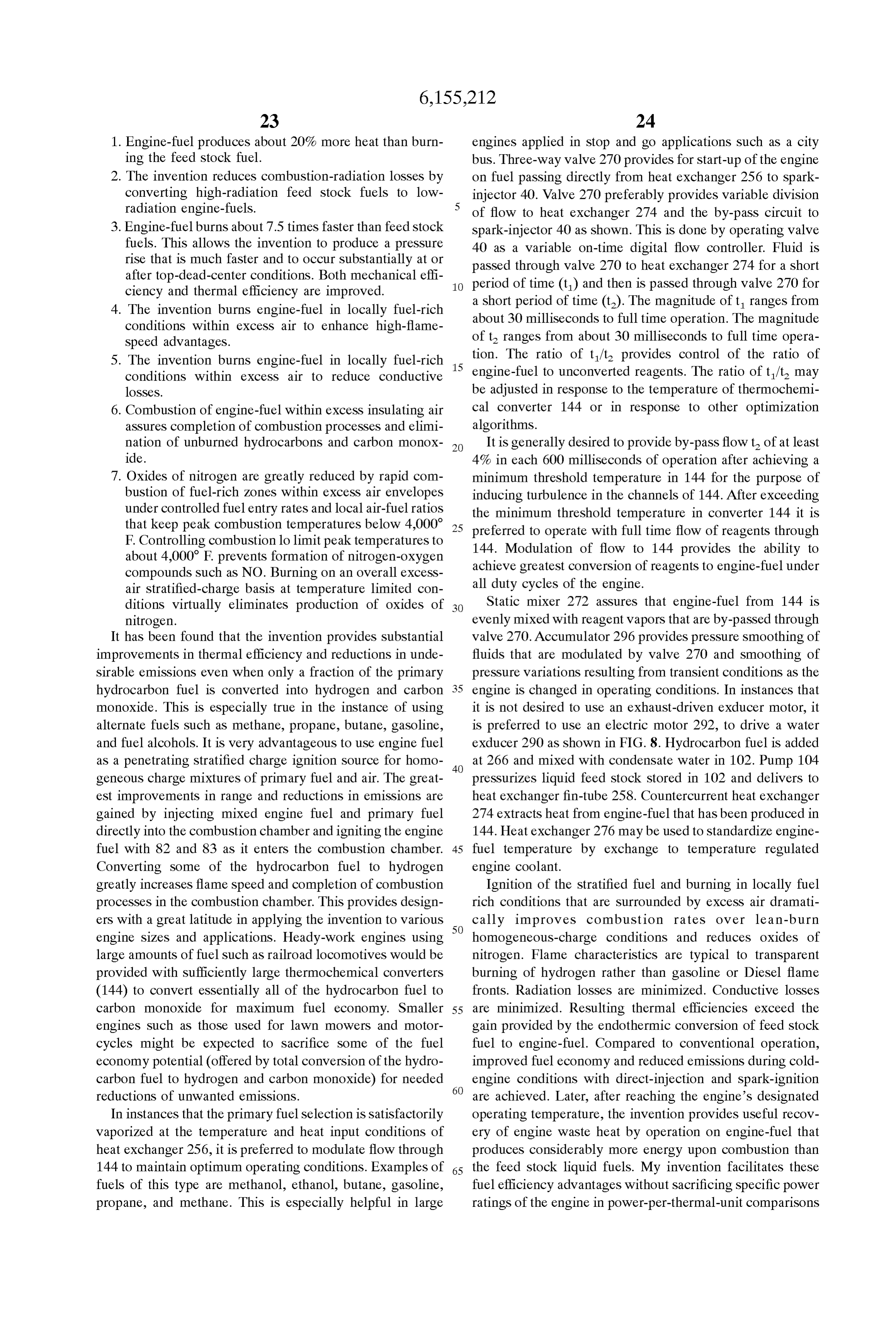
Page 21
and is applicable to gas turbines, rotary-combustion, and Such piezoelectric material (PVDF) is also available in piston engines of two- and four-stroke designs. Various thicknesses and dimensions from Pennwalt A Suitable polymer tube 61 Such as tetrafluoroethylene as Corporation, Valley Forge, Pa. 19482. It has been found that shown in FIG. 2 allows polymer dielectric 64 as shown in a PVDF disc 63 having the outside diametrical dimension of FIG. 9 to transmit greater force from bore 61 as a result of 5 the bore of case 44 at the location of valve seat 54, an inside pressure differences within the bore 61 and the ambient bore dimension of the O-ring gland as shown, and a thick pressure outside of wall 76 of tube 44. The radial force neSS of about 50 micrometerS Serves well as a fuel-pressure transmitted to wall 76 by dielectric 64 is met by an equal and and combustion-chamber monitor. It is preferred to apply opposite force by elastically-Strained Surrounding tubular electrodes to the faces that contact valve Seat 54 and steel wall 76 to contain the assembly as shown. dielectric 64.
Removal of the ceramic tube 60 also allows polymer In the instance that a piezoelectric disk 63 is used it is dielectric 64 to transmit greater force to Valve Seat 54 as a preferred to Select the material for making dielectric body 64 result of preSSure differences between the compression with sufficient Poisson displacement from forces exerted by chamber beyond dielectric 72 and valve seat 54. By provid 15 fuel preSSure to develop a Substantial anal force and result ing a force or “preSSure' transducer 63 between Valve Seat ing piezoelectric Signal on transducer disc 63. In this 54 and dielectric polymer 64, fuel injection and other events of engine operation can be instrumented. This aspect of the instance it is preferred to Select a relatively low modulus of invention is shown in FIG. 9. Especially useful pressure elasticity material Such as unfilled ethylene tetrafluoroeth transducers for this purpose are Strain gages and piezoelec ylene rather than a Stiffer material Such as glass-filed tric including ceramics Such as quartz and barium titanate, polyphenylene Sulfide.
and polymers such as polyvinylidine fluoride (PVDF). Another Suitable form of piezoelectric Sensor is a right O-ring 62A in valve seat 54 can be made of Such material to circular cylinder such as 65, 67, or 69 located as shown in perform both Sealing and preSSure transducer functions. FIG. 9. Cylindrical piezoelectric transducers are available in Deformation of the material produces a Voltage Signal that 25 outside diameters of 6.35 to 25.4 mm (0.25" to 1.00") with can be monitored to determine fluid pressure within the nominal wall thicknesses of 0.51 to 1.27 mm (0.02" to passage way from Valve Seat 54 to nozzle 70. Axial force 0.05M) and in cylindrical lengths up to 300 mm or 12". Such resulting from pressure variations in the combustion cham devices can be special ordered from Atochem Sensors, P.O. ber is also indicated by piezoelectric O-ring 62A in valve Seat Box 799, Valley Forge, Pa. 19482. Pressure transmitted from 54. fuel passing through tubular space 61 and combustion Masking O-ring 62A and metallizing with conductive ink chamber pressure cycles cause piezoelectricS 65, 67, or 69 to or by Sputtering NiCu electrode patterns on the Surface of the generate electrical signals. Pressure rise and fall in the O-ring allows the Voltage Signal to be taken out of the combustion chamber is transmitted through component assembly by a Suitable electrical cable to an external con 35 assembly 55, 70, 72, and 64 to generate piezoelectric Signals troller. Electrode patterns can be designed to emphasize the on transducers 62A, 63,65.67 and 69. This allows monitor Signal for fuel preSSure monitoring or to emphasize the ing the combustion chamber to determine operating condi Signal for combustion chamber pressure monitoring or it can tions Such as intake, compression, power, and exhaust be designed to monitor both activities. 40
Determining the approach to top dead center and the trend
For monitoring the fuel pressure Signal it is preferred to in piston Speed as a result of fuel injection and ignition provide a metallized electrode around the greatest or outside characteristics allows rapid optimization of fuel-injection diameter of the o-ring and to provide another opposing and Spark-ignition. This approach to preSSure measurement electrode at the Smallest or inside diameter. The piezoelec and characterization of piston Speed, fuel injection, ignition, tric force Signal is taken from the outside electrode to a 45 and combustion provides faster and much more comprehen controller outside of the fuel injector 40. It is preferred to Sive control and optimization of engine processes than make valve Seat 54 of a Suitable dielectric material Such as conventional approaches of instrumentation and control. Sintered alumina or other ceramic material however it has In operation, force transducer 63, force-detecting O-ring been possible to coat metal Seats with powder-coated and 50 62, or transducerS Such as 65 are monitored by connection Sintered dielectricS Such as perfluoroalkoxy polymer to of their electrodes to a Suitable electrical circuit for deter produce a dielectric coating Sufficient to electrically isolate mining the occurrence of piezoelectric Signals. Other Suit the pressure transducer Signal. able pressure transducers for determining the condition of In instances that emphasized monitoring of combustion combustion chambers Served by the combination fuel injec chamber pressures is desired it is preferred to mask the 55 tor and spark ignition device of FIG. 9 include: O-ring for application of opposing electrodes on the areas 1. Fiber optic devices in which an interferometric cavity that contact the face of dielectric 64 and the parallel face of resonator is located between the end face of an optical the o-ring groove in valve Seat 54. This arrangement empha fiber and a thin reflective silicon wafer chip. The chip sizes Voltage production between the electrodes for axial 60 acts as a diaphragm and flexes with differential preSSure forces due to combustion chamber preSSures. or with motion of Surrounding materials that deform as Another electrode pattern that has been found to be best a result of preSSure within the fuel conduit and due to for monitoring both fuel pressure and combustion chamber pressure within the combustion chamber. This flexing of the diaphragm changes the cavity depth as a function preSSure is provided by applying the electrodes about half of the diaphragms radius and modifies the overall way between the two locations described above. This pro 65 Spectral reflectance of the light relative to the pressure. vides Substantial signal for fuel-injection and combustion Any of four basic variables of intensity, frequency, chamber events. phase, or polarization may be Selected to Sense preSSure
Page 22
by this fiber optic instrumentation. Intensity modula Speed and load are examples of instances where dynamic tion is a simple illustration in which the total intensity optimization is preferred.
of reflected light indicates the pressure of the fuel Advantages of the invention are also beneficial in com conduit and the combustion chamber. A Suitable Source bination with more traditional Adaptive Control Techniques for such a device is Fiber Optic Sensor Technologies of by providing a very fast analysis of operations and trends. Ann Arbor, Mich.
2. Polysilicon piezoelectric gage elements bonded by This fuel-injection and combustion-chamber information provides a much more intimate and instantaneous picture of chemical vapor deposition or molecular bond adhesion engine operation than previous instrumentation. With instan to a temperature matched Substrate Such as tube 60 of taneous information, extremely rapid adaptive control opti FIG. 2, or to the face of seat 54. Such devices are available from Rosemount, Inc. of Eden Prairie, Minn., mization occurs for fuel injection and ignition parameters and from Dresser/Ashcroft of Stanford, Conn. Such as delivery timing, pressure, and penetration pattern. 3. Capacitance Sensors with two-way transmitters using These parameters can be managed by the engine controller fiber optics, Smart, or fieldbus communications. All to produce very high fuel efficiencies and minimal oxides of versions use a microcapacitance Silicon Sensor. Such 15 nitrogen by plasma ignition of entering fuel in fuel-rich devices are available from Fuji Instruments, Ltd. of mixtures followed by completion of combustion in far Tokyo, Japan. See FIG. 9 regarding 55 as a fiber optic exceSS air conditions with the result being reduced peak coupling arrangement. combustion temperature, reduced oxides of nitrogen, and 4. Ceramic diaphragms may be used in capacitance pres faster completion of combustion to fully oxidized products Sure Sensors. PreSSure Sensors of this type are Suitable of combustion. Application of the invention with adaptive and are available from Endress+Hauser Instruments of
Greenwood, Ind.
control techniques is preferred in engines that operate for 5. Tuning fork instrumentation to determine pressure as a long periods with relatively slow changes in load and Speed conditions. Examples are locomotives, barges and air planes change of frequency is Suitable and Such pressure 25 transducers measure the natural frequency with piezo in which the engines operate with relatively slow changes in electric elements. Such devices are available from load conditions and where two or more engines may be Yokogawa Corporation of America in Newman, Ga. coupled to the same load and require Speed matching. Fuel 6. Fiber optic devices in which the intensity of reflected flow is compared to the flow and combustion results in other light is modified by a pressure deformable metallized combustion clambers and is varied to produce the maximum mirror. The end of the fiber is fitted with a diaphragm brake mean effective pressure for the least fuel consumption having a reflective Surface that acts as a variable and least emissions of pollutants. In addition to reflector. The diaphragm flexes with differential pres optimization, the invention provides extremely rapid fail Sure or with motion of Surrounding materials that Safe monitoring to prevent damage to an engine due to a deform as a result of pressure within the fuel conduit 35 stuck open fuel control valve. For instance, if valve 48 or 82 and due to pressure within the combustion chamber.
This flexing of the diaphragm changes the amount of should Stick open the fuel pressure discrepancy in 61 would reflected light as a function of the diaphragm's radius be immediately detected and characterized as an abnormal and modifies the Overall spectral reflectance of the light event and the fuel Supply could be shut down or brought to relative to the pressure. 40 a reduced pressure by controller 370 as shown in FIG. 10 in In operation, transducer 63 develops a Signal in response a Small fraction of the time that conventional control Sys to pressurize increases within bore 61 as fuel passes to the tems require. Excess fuel flow would be detected before combustion chamber. Detection and characterization of this other conventional instrumentation could detect a speed fuel flow is an important diagnostic Step in assuring pre change in the crank Shaft. This is an extremely important cisely timed delivery of the fuel to the combustion chamber 45 Safety-assurance feature.
and in optimization of engine control. Combustion chamber In conventional control Systems for electronic fuel injec events including intake, compression, Stratified-charge fuel tion a Stuck-open fuel control valve in a multiple cylinder introduction, ignition, combustion, and expansion are moni engine would go undetected at least until the crank Shaft or tored by one or more pressure transducers 62A, 63 and 65. 50 camshaft changed speed and probably for many revolutions It is preferred to control Some engines with a behavior-based before being detected. In the present invention it would be approach Such as the Neuronal Group Selection disclosed by detected in the first abnormal fuel pressure occurrence and Wade O. Troxell in a “A Robotic Assembly Description the controller could determine the optimal course of action Language Derived from Task-achieving Behaviors' to accomplish the desires of the operator for best Safe Proceedings, Manufacturing International 90. Atlanta, 55 performance. Corrective action would occur on the next march 1990; and by Tim Smithers and Chris Malcolm in combustion chamber ready for fuel injection, ignition, and “programming robotic assembly in terms of task achieving power production.
behavioral modules' DAI Research Paper No. 417, Edin Determination of discrepancies Such as low fuel pressure burgh University, Department of Artificial Intelligence, are also provided by the present invention. Partial plugging 1998; and by D. B. Killelson, M. J. Pipho, and L. L. Franklin 60 of individual fuel filters for each embodiment 40 can be in “Dynamic Optimization of Spark Advance and Air-Fuel compensated by providing longer fuel flow times in Such Ratio for a Natural Gias Engine” SAE paper 892142 in combustion chambers. This aspect of the invention provides SP-799 Gaseous Fuels: Technolog and Emissions, Society of compensation or correction of partially performing Sub Automotive Engineers, 1989. These references being incor 65 Systems long before a change in engine performance could porated herein. High Speed engines driving lawn mowers, be detected by conventional approaches. By directly inject motor cycles, and hand tools that undergo rapid changes in ing fuel into each combustion chamber, correctional opera
Page 23
tion and maintenance of desired engine Speed and torque and ignition timing with respect to the fuel-combustion production can be achieved much more rapidly than with characteristics, compression ratio, geometry, and dimen previous approaches to fuel management in which homo Sions of the combustion chamber allows production of geneous air/fuel mixtures are prepared in the intake System optimum results. Such as minimum oxides of nitrogen, maxi of the engine. mum power, maximum fuel economy or minimum operating As provided in FIGS. 7 and 8, water is recovered from the noise. Feedback of the resulting temperature of combustion, exhaust Stream of a combustion engine. This water can be piston Speed, pressure rise, and presence of oxides of electrolyzed to produce hydrogen. Any Suitable electrolyzer nitrogen in the exhaust allows adaptive controls to precisely may be used including types that allow production of control the engine.
mixtures of hydrogen and oxygen A Summary of electrolysis Suitable photo-electronic sensors 53 for determining the technology is found in the article “Intermediate Temperature combustion chamber temperature include light-actuated Water Vapor Electrolysis” by M. Schriber, G. Lucier, J. A. SemiconductorS Such as photo-diodes, photo-transistors, and Ferrante, and R. A. Huggins, Int. J. Hydrogen Energy, Vol. photo-resistors. It is preferred to communicate Such devices 16, No. 6, pp. 373-378, 1991, and is incorporated herein. 15 to the combustion chamber through a light pipe to the For vehicles that need peak engine performance by utiliza combustion chamber. It has been found to be suitable to tion of as much exhaust energy as possible in turbocharging locate Such devices 53 at the light gathering apex of a the electrolyzer disclosed by J. F. McEloy in “SPE Regen truncated concentric light transmitting dielectric Sleeve 55 erative Fuel Cells For Space and Marine Applications' pp. within the protective mass of dielectric 64 as shown in FIG. 282-285, Fuel Cell Seminar, November 1990 is preferred. It 9. Light pipe sleeve 55 extends to the combustion chamber is preferred to use the embodiment shown in FIG. 10 to as shown to gather light for Sensor 53. It is preferred to make reduce electrical energy requirements by recovery of waste light pipe sleeve 55 from a Suitable high-temperature mate heat. rial Such as glass, quartz, or Sapphire. The Signal produced Oxides of nitrogen are greatly reduced by using the 25 by combustion-chamber monitor 53 is preferably taken to instrumentation described and adaptive control System of controller 370 by an internal connection 52A through a well FIGS. 9 and 10 for monitoring rapid combustion of fuel-rich in dielectric 64 similar to the one shown at 50 with a Suitable Zones within exceSS air envelopes under controlled fuel connector 52A similar to 52 as shown in FIGS. 2 and 9. entry rates and local air-fuel ratios that keep peak combus Instrumentation-connector wells Such as 50A, 50B, 50C tion temperatures below 4,000 F. Controlling fuel admis (similar to 50 and SOA but not shown) for transmitting Sion rate and ignition timing can limit peak temperatures to instrumentation signals from 53, 62A, 63, 65 and 67 are about 4,000 F. and prevents formation of nitrogen-oxygen preferably arranged as needed at Suitable heights and cir compounds such as NO. The invention makes it possible to cumferentially rotated positions between 50 and 66 to allow correlate combustion pressure rise characteristics as 35 ease of installing connecting leads to controller 370. detected by sensors 62A, 63, or 65 with peak temperature In many vehicles approximately 50 percent of unwanted determination by a suitable light pipe 55 which conveys exhaust emissions occur at Start-up and during cold engine combustion chamber radiation to suitable photodetector 53. conditions. Hydrogen can be generated by electrolysis or AS shown light conducting material Such as quartz, glass, or 40 thermochemical regeneration and Stored for use during Sapphire in the form of a fiber or coaxial sleeve 55 conveys cold-Start conditions to prevent Such pollution. Waste heat light emissions from combustion to photo-electronic Sensor from a combustion engine usually exceeds the energy con 53 to monitor combustion as a function of the fuel verted to shaft works. This waste heat can be used in characteristics, pressure of delivery, rate of fuel delivery, endothermic electrolysis or endothermic thermochemical or timing of injection, and timing of ignition. This information 45 endothermic electrochemical conversions to reduce the elec may be used as the individual control parameter or in trical energy required for electrolysis. Accordingly, elec conjunction with other Sensors previously disclosed includ trolysis of mixtures of substances shown in Table 3 such as ing 62, 63, 65, 67, and 69. water and ammonia illustrates endothermic electrochemical Preventing the temperature of combustion from exceed 50 conversion. FIG. 10 shows an apparatus for elevated tem ing 4000°F. is achieved by controller 370 as shown in FIG. perature electrolysis. In remote locations especially where 10 using feedback from one or more sensors 62, 65, 53, water is Scarce, or for driver convenience in any location or and/or 55 in the embodiment of FIG. 9. In high production climate it is preferred to use water in the electrolysis, engines it is Sufficient to determine the operating parameters thermochemical, and electrothermochemical processes that for each fuel Selection in particular engines through dyna 55 has been recovered from the exhaust Stream of the combus mometer testing of power and emissions characteristics and tion engine by embodiments such as those shown in FIG. 7 development of a Safe envelope of operating parameters or FIG. 8.
including feedback from 62A, 63, or 65 which is compared In operation of the embodiment of FIG. 10, a combustion with values from memory of the electronic controller as a 60 engine 300 depicted generally as a piston engine as shown map which has been previously referred to as Map A, Map operates with a Supply of air from inlet compressor 302. B, and So forth. Burning on an overall exceSS-air Stratified Following combustion, exhaust gases travel to cylindrical charge basis at temperature-limited conditions virtually electrolyzer 304 for purposes of heating the electrolyzer. eliminateS production of oxides of nitrogen. Engines utiliz Water from a suitable source is added to the electrolysis cell ing the present invention can be optimized for minimizing 65 304 after heat exchange in 306 with elevated temperature oxides of nitrogen while achieving best economy. Adjust hydrogen and oxygen from electrolysis cell 304 as shown in ment of the fuel-injection initiation timing, fuel-flow rate, FIG 10.
Page 24
Electrolysis is carried out within 304 using direct current Vacuum-assisted Sub-Systems. Such as wheel or drive-line applied to concentric right circular cylinder electrodes 308 brakes, windshield wipers, and numerous other conve and 312. Semipermeable membrane cup 310 Separates con niences. However, this creates a problem for unthrottled air centric chambers within which cylindrical electrodes 308 intake which is the preferred mode of operation because the and 312 are located. An eutectic of NaOH and KOH salts intake System no longer produces a vacuum. Actuator 348 provides a suitable electrolyte for the innermost chamber controls air valve 350 preferably at times that brakes are where water is added from tube 360 to conduit 364 and applied to produce a vacuum in line 356 to assist actuation where concentric oxygen electrode 312 is located. The same of a representative vacuum-assisted device 358 as shown. electrolyte may be used in the outer chamber, however Vacuum Storage in accumulator 354 is monitored by a lithium hydride, potassium chloride, Sodium chloride, and suitable pressure transducer 355 to allow controller 370 to lithium chloride form suitable eutectic salt electrolytes for determine the frequency and degree of application of valve the Surrounding chamber in which concentric hydrogen 350 as required to maintain the desired pressure difference electrode 308 is located. Temperatures above about 177 C. for the type of driving undertaken at any time. Check valve or 350° F (or the maximum exhaust temperature) are 15 357 retains accumulated vacuum as shown.
Suitable for operating the electrolyzer. Suitable electrode For instance, if Vacuum assisted wind-shield wiperS are materials are type 302 stainless steel for 312 and nickel used controller 370 will maintain the required vacuum in screen for electrode 308. Membrane 310 can be made of any 354 by more frequent or more extensive restriction of air Suitable proton or hydrogen ion permeable material includ entry to the engine past valve 350. The preferred time of ing materials designed for electrodialysis Such as those application of valve 350 would be during vehicle Stopping or based on inorganic materials. Such as ceramics or metals that deceleration events. However, controller 370 will provide provide oxidation and hydrogen-embrittlement resistance. It use of valve 350 as necessary to maintain Safe driving is preferred to use a thin membrane of Silver-palladium conditions in correlation with the optimization parameters which Serves as a common negative electrode to both 25 disclosed for control of 40 with respect to engine power, electrodes 312 and 308 in instances that long life is man emissions, and fuel economy. A normally-closed dump valve datory. For automotive applications it is Sufficient to use 359 relieves compressor 302 as needed until more efficient palladium coated iron-nickel and iron-manganese alloys operation is resumed. At times that fuel pressure is Such as the austenitic Steels. insufficient, illustratively due to fuel-storage depletion or Positive voltage is applied to each electrode 308 and 312 failure of the fuel-pressurization System, to allow direct through lugs 320 and 316 as shown. Negative voltage is injection of fuel to the compression chamber it is preferred applied to lug. 318. It is preferred to use Several electrolyzers to actuate valve 350 to reduce air entry to the engine to like the unit cell shown in Series or built up with concentric reduce compression preSSure and if this does not allow electrodes connected in Series to provide a full load for 35 Satisfactory engine performance to deliver fuel to the com higher Voltage Systems. Such as 12–240 volt Systems. Each bustion chamber during intake conditions. In many engines, electrolyzer unit cell requires about 1.1 to 1.5 volts depend delivery of the fuel during intake conditions may require ing upon the temperature of operation. continuous actuation of valve 350 in proportion to the Electricity for operation of electrolyzer 304 may be 40 amount of fuel delivered to produce a more or less homo generated by one or more on-board generators 380 through geneous air-fuel mixtures until fuel preSSure is restored typical output 319, 319A, 319B etc. connected to 318, or it Sufficiently to allow preferred operation at Stratified-charge may come from rectified utility grid power (not shown) conditions.
during times that the vehicle is parked at facilities for Hot hydrogen and oxygen exiting electrolyzer 304 are charging. It is preferred to use electricity generated by 45 cooled by preheating entering water in heat eXchanger “braking” generator(s) 380 during times that the vehicle is assembly 306 as shown. It is preferred to insulate electro decelerated. Illustratively, converted Diesel-electric locomo lyzer 304 with high temperature rock wool or similar tives can use the braking action of the wheel drives to deliver materials to keep inventories of electrolyte molten for hours electricity to electrolyzer 304 to recover braking energy. 50 after shut down of the engine. This provides for recovery of When deceleration is desired, the regenerative brakes are waste heat as chemical potential energy through elevated applied and these generators develop electricity for electro temperature electrolysis. Hydrogen is Stored in preSSure lyzer 304. This provides recovery of vehicle kinetic energy accumulator 314.
as chemical potential energy in the form of engine-fuel for Storage pressure of hydrogen is determined by the pres use when propulsive power is needed. In addition to the 55 Sure maintained by pump 346. This balances the preSSure types used by rail locomotives, generators Suitable for this acroSS membrane 310 at a typical Storage preSSure of about purpose include the Standard engine-driven alternators, driv 140 atmospheres. Regulation of hydrogen pressure to Spark eline generators, and Special motor/generators in the wheels injector 40 is preferably accomplished primarily by Solenoid of vehicles. When the battery (not shown) is adequately 60 valve 322 which is opened when the pressure is below a set charged, it is preferred to apply the output of a Standard or point and closed when the pressure reaches a Set point auxiliary automotive generator 380 as provided by controller Another conventional pressure regulator may be used in 370 to electrolyzer 304 at times that the brake petal is Series if desired but it is preferred to use at least fail-safe applied. This improves vehicle efficiency and performance regulator 322. It is preferred to locate pressure regulator 322 by recovering Stopping energy for use as engine-fuel. 65 inside of accumulator 314 as shown So it cannot be impinged In automotive applications it is often desired to retrofit and broken off without destroying accumulator 314 and will engines in vehicles that depend upon commonly used fail safe in case of collision. If the vehicle is in a collision
Page 25
and the air bag or Safety harneSS is activated fail-safe valve Exhaust gases enter the atmosphere through 376 as shown. 322 is returned to the normally-closed condition. Reactiva It is anticipated that in certain applications, the embodiments tion of pressure regulation requires action by the operator to of FIGS. 9 and 10 will be used in conjunction with the Signal that it is Safe to continue fuel delivery to Spark embodiments of FIGS. 7 or 8. The present invention assists injector 40. A suitable action would be to reset a Switch. virtually any fuel by improved combustion efficiency. The Using off-peak electricity to generate clean hydrogen embodiments of FIGS. 2-10 can be used independently or in transportation fuel is an especially opportune way for exist conjunction with Standard fuel metering equipment Such as ing electric generating capacity to help Solve the problem of diesel fuel injectors, carburetors, throttle body injectors, and air pollution. Off-peak wind, wave, falling-water and other port injectors such as 390 from fuel line 392. In this instance forms of renewable electric power are especially desired for it is generally preferred to operate at “lean burn' conditions an embodiment of the invention that gets the car ready for that are too lean for Spark ignition. daily use of hydrogen while the car is parked. The parked Although it is generally preferred to burn all of the fuel on vehicle is manually or automatically coupled by Suitable a Stratified basis, it has been found that using hydrogen contact wiring or inductive coupling to an electricity Supply. 15 produced by the embodiments of FIGS. 4-10 and delivered Electrolyzer 304 may be heated by application of alternating by the embodiment of FIG. 9 dramatically improves com or direct current to electrodes 316/318 and 320/318 for bustion efficiency and power ratings of more inert traditional Suitable warm-up. hydrocarbon fuels delivered by standard systems. This pro After reaching the desired temperature, direct current is ceSS of characterizing the combustion of more inert conven applied between electrodes 308 and 312 (positive) and 310 tional fuels by the hydrogen-torch effect is valuable even at (negative). Pump 346 is activated to supply fluids to the 2 percent or leSS heat delivery from the hydrogen Using center chamber of 304 through tube 364. Pump 346 delivers hydrogen to Stimulate combustion of hydrocarbon fuels fluids from 331 to heat exchanger 306, to 364, and maintains allows leaner burning of fuels than could be ignited by preSSure equilibrium acroSS 310 at the instantaneous hydro 25 conventional Spark plug approaches and increases the rate of gen Storage preSSure. Normally open Solenoid valve 362 is molecular-cracking processes in which large hydrocarbons actuated to closed position and opened intermittently in are broken into Smaller fragments. Expediting production of coordination with preSSure regulating valve 322 to maintain Smaller molecular fragments is beneficial in increasing the the instantaneous hydrogen Storage pressure balance by Surface to-volume ratio and consequent exposure to oxygen allowing bleed off of oxygen to the inlet of the engine as for completion of the combustion proceSS. Improvements shown. It is preferred in normally aspirated engines to bleed similar to those shown in Table 1 for methane-hydrogen this oxygen into the inlet at a point as close to the combus mixtures are possible when hydrogen is used as a combus tion chamber as possible. It is preferred to bring the tem tion Stimulant with other hydrocarbons Such as methanol, perature of 304 to the upper limit of temperature while on 35 ethanol, gasoline, and diesel fuel. This is especially advan parked charge So that when the vehicle Starts operating it tageous in lean-burn conditions. It is preferred to use 100 will be ready to accept conversion of Stopping energy as percent hydrogen on cold Start, idle, and in polluted cities Stored hydrogen. This can be done by programming the and to use engine-fuel or hydrogen-boosted fossil fuel if parked vehicle charging System to charge the hydrogen 40 necessary for greater range.
accumulator to within about 10 percent of the maximum Hydrogen burns in exceSS air to produce water vapor and Storage pressure as Soon as the car is parked in order to take very limited amounts of NO depending upon the peak advantage of the heat accumulated in 304. A Suitable pro temperature of combustion as controlled by the optimization grammable timer is a Grainger Stock No. 685. Near the objective of controller 370. Worthy reductions in emissions expected end of the programmed park period the electro 45 of NO, CO, CO, HC, and SO, and particulates are lyZer is reheated and the accumulator is charged to the possible when hydrogen is used as a Substitute for nearly any design pressure to be ready for at least starting and warming portion of gasoline and diesel fuel. Tables 1 and 2 show the engine on hydrogen before introducing a fuel containing comparisons of emissions from vehicles using the invention carbon.
with various percentages of hydrogen and other fuels. It
This mode of operation reduces unwanted exhaust emis shows that relatively Small amounts of hydrogen can dra Sions by up to 50 percent. For many motorists in Stop and go matically reduce exhaust emissions of atmospheric pollut traffic, the vehicle would be operated on hydrogen without ants and achieve Stringent exhaust emission limits. AS the use of fossil fuels. This mode of operation reduces shown in Table 1, ultimately clean exhaust conditions can be unwanted emissions by almost 100%. It is preferred to 55 met by increasing the percentage of hydrogen or engine-fuel. operate the combustion engine with the Special water Use of hydrogen as a cold-start and pilot fuel for land-fill condensing turbocharger shown which consists of compres methane, natural gas, and Sewer gas is encouraged. Con Sor 302, drive shaft 324, turbo-motor 326, stator 328, and ventional waste disposal practices that release large Volumes turbo-motor 330. Condensed water is collected in centrifu of harmful greenhouse gases Such as methane and carbon gal separator 332 and delivered to reservoir 331 as shown. 60 dioxide can be replaced by processes that collect renewable Exhaust gases pass around electrolyzer 304 in a helical path hydrogen and methane from landfill and Sewage treatment as shown in section at 334, 336, 338, 340, and 342. This plants for use in cogeneration and transportation applica provides heat to electrolyzer 304 and helps insulate 304. tions. Costly waste disposal practices that pollute the envi Final insulation (not shown) is placed on the outside of the 65 ronment can become profit centers as clean-burning renew assembly to conserve heat It is preferred to use a vacuum able hydrogen and methane are collected and marketed as jacketed insulation System like the Venerable thermos bottle. renewable fuels that replace diesel and gasoline fuels.
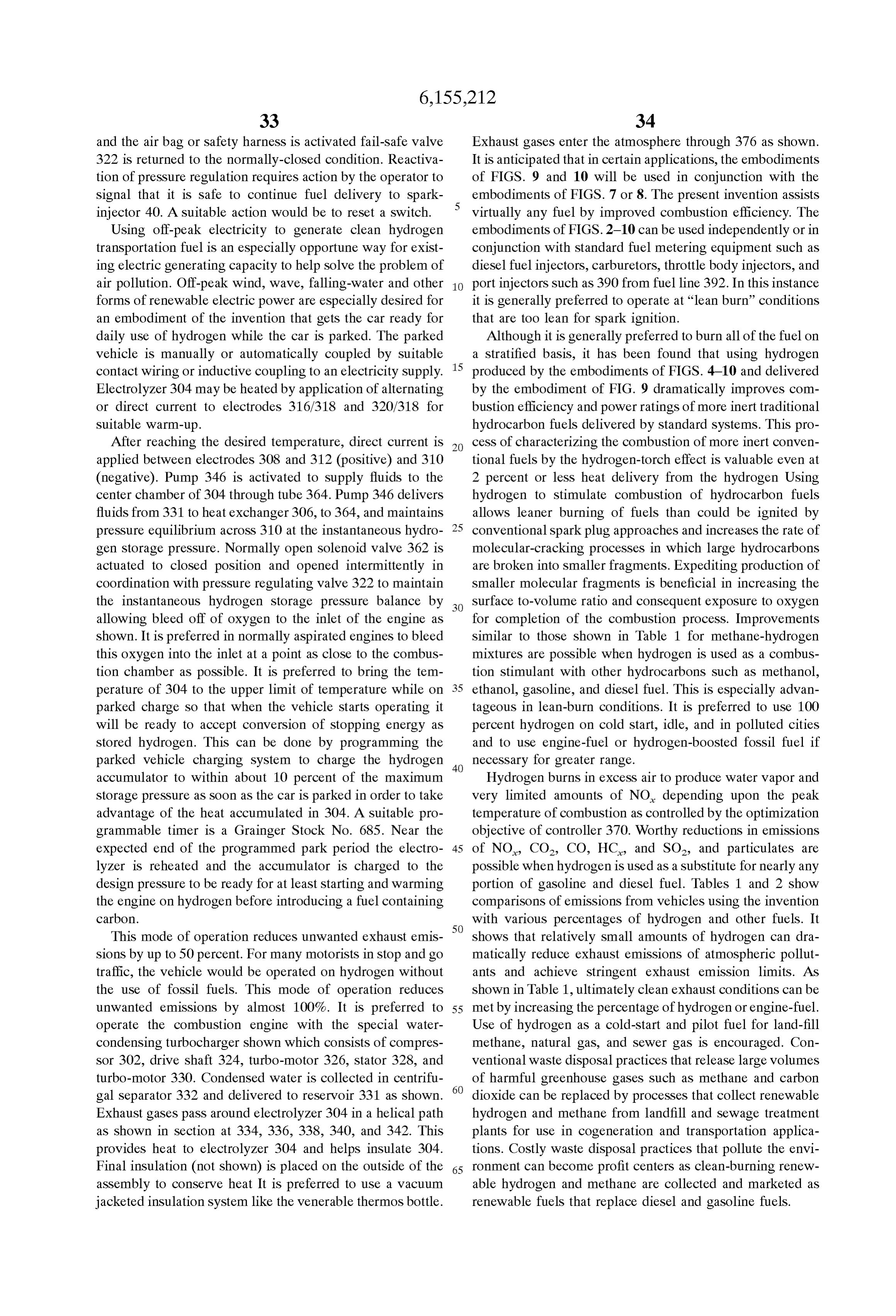
Page 26
It thus will be understood that the objects of this invention have been fully and effectively accomplished. It will be TABLE 3-continued realized, however that the foregoing preferred specific ENGINE-FUEL PRODUCTION embodiment has been shown and described for the purpose of illustrating the functional and Structural principles of this REACTANTS FEEDSTOCKS ENGINE-FUEL invention and is Subject to change without departure from Alcohol: CHOH + Such principles. Therefore, this invention includes all modi 5HO-> fications encompassed within the Spirit and Scope of the Methanol-Phenoll: CHOH + CHO + 7CO + 1 OH, - Eqn. 6
following tables and claims. 144-Proof Ethanol: CH-OH + HO-> 2CO + 4H, - Eqn. 7
TABLE 1. (130-Proof): CHOH->
EMISSIONSTEST SUMMARY Gasoline-Wet CH + CH-OH + 9CO + 19H - Eqn. 10
EMISSIONS GRAMS PER MILE* 15 Diesel-Wet CH + CH-OH + 10CO + 21H, - Eqn. 11
TEST OR STANDARD RHC CO NO Cyanoacetic Acid C.H.NO + HO-> 3CO + 2.5H2 +.5N - Eqn. 12 Ammonia 2NH-> N + 3H - Eqn. 13 5% HYDROGEN, 95% O.O6 1.6 O.38 Ammonium 2NH4OH-> N + 3H + 2H2O - Eqn. 14 METHANE2 Hydroxide?
50% HYDROGEN, 50% O.O3 0.4 O.23 NOTES:
METHANE
100% HYDROGEN2 O.O O.O O.18 ''. Equation 1 illustrates the opportunity to utilize greater biomass alcohol CALIFORNLATLEV O.125 3.4 0.4 yields such as methanol from destructive distillation of ligno-cellulosic CALIFORNIALEV O.O75 3.4 O.2 materials and fermentation of starches. Considerable water can be left in CALIFORNIAULEV O.O40 1.7 O.2 the crude alcohols to reduce refining costs. °. Typical to the variety of compounds in partially-refined biomass and 25 coal-tar fuels.
NOTES:
". RHC = Reactive Hydrocarbons . "Gasoline” typical to a mixture of components such as undecane, °. % Hydrogen injected through spark-injector 40 decane, nonane, octane, heptane, hexane, pentane, benzene, toluene, and (casionally) fuel alcohols.
. Transitional Low Emission Vehicle (CARB) '. Typical to the variety of cyanocarbons and cyano-organic compounds. “. Low Emission Vehicle (CARB) l. Typical to the variety of ammonium compounds. . Ultra Low Emission Vehicle (CARB) * CARB = California Air Resources Board
TABLE 2
FUEL COMBUSTION CHARACTERISTICS
LOWER UPPER LOWER HIGHER FLAME
FLAME FLAME HEAT RELEASE HEAT RELEASE AIR-FUEL SPEED*
FUEL LIMIT LIMIT (BTU/lb) (BTU/lb) RATIO (Ft/Sec.) HYDROGEN 4% VOL. 75% VOL. 51,593 61,031 34.5 LBS/LB 30,200 CARBON MONOXIDE 12 74.2 4,347 4,347 2.85 METHANE 5.3 15 21,518 23,890 17.21 4,025 ETHANE 3 12.5 20,432 22,100 16.14 4,040 PROPANE 2.1 9.4 19,944 21,670 15.65 4,050 BUTANE 1.8 8.4 19,679 21,316 15.44 4,060 BENZENE 1.4 7.1 17,466 18,188 13.26 4,150 METHANOL 6.7 36.5 7,658 9,758 6.46 3,900 ETHANOL 3.2 19 9,620 12,770 8.99 4,030 OCTANE 19,029 20,529 15.11 4,280 HEXANE 1.18 7.4 4,200 GASOLINE 1.O 7.6 18,900 20,380 14.9 4,010
* At Atmospheric Pressure
TABLE 3
ENGINE-FUEL PRODUCTION
REACTANTS FEEDSTOCKS ENGINE-FUEL
Methanol-Ethanoll: CHOH + 3CO + 6H, - Eqn. 1
Methanol-Propanol: CH-OH + 4CO + 8H, - Eqn. 3
CHOH + 2HO->
Methanol-Butanol: CH-OH + 5CO + 10H - Eqn. 4
Ethanol-Amyl CH-OH + 7CO + 14H - Eqn. 5
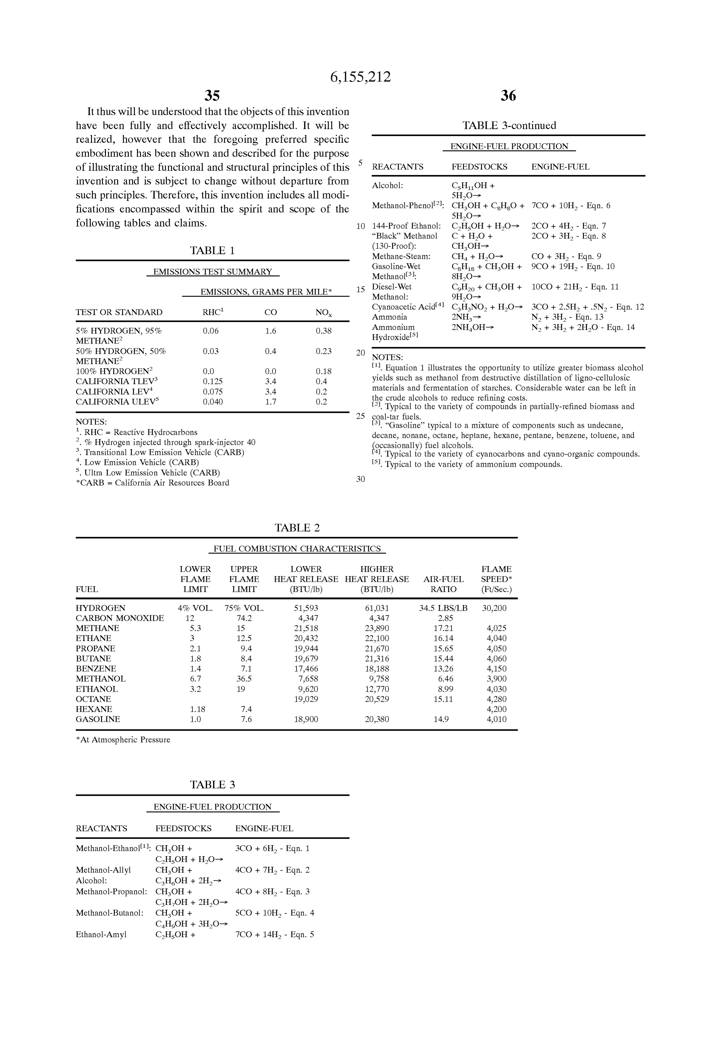
Page 27
TABLE 4
CATALYTIC MATERIAL SYSTEMS
BASE CAT T.S. Y.S. ELG. Melt matl matl Ag Cui. An Sn: Si: Mg. Cdr Al PSI PSI % F. Alloy - 95%. 5% - - - - - 30000 10000 40
Sheet
Alloy - 80%. 20% - - - - - 38000 12000 52
Sheet
Alloy - 70%. 30% - - - - - 40000 11000 85
Sheet
Alloy - 70%. 26% 2% - - - - 53000 22000 63
Sheet
Alloy - 60%, 35%. 1%. 19% - - 3%. 58OOO 25OOO 45
Sheet
Fe+2 Hot Dip - 57%. 42% 1% 1640 Coat
Cui Hot Dip 45%. 15%. 16% 24% 1135 Coat
A* Hot Dip 3%. 6% - 5%, 60% - 25% - 940 Coat
Fe Hot Dip 7% 48%. 38%. 1% 1% 1%. 2%. 2% 1485 Coat
Fe*1. Hot Dip 10% 60%. 25% 1205 Coat
Fe Hot Dip 22% 4.8% 1% 27%, 2% 112O Coat
NOTES:
* = Composition of Catalysts **= Fe = low alloy and stainless steels * = Cu = Including brass, bronze, and monel alloys * = Al = Aluminum alloys * = Plus 5%. Phosphorus
Processing of Hot Dip Coatings May Require Inert, Vacuum, or Hydrogen Furnace Atmospheres
What is claimed is: substantial amount of said fluid is held in storage prior to 1. A heat engine energy conversion process including participation in Said energy conversion process. expanding means for expansion of a gaseous inventory to do 35 7. The energy conversion process of claim 1 wherein a useful work on a moveable output means of Said engine and portion of the inventory of said fluid is extracted from said including exhausting means for expelling the exhaust from exhaust by means Selected from the group including an Said engine, the improvement comprising: electric motor driven exclucer means, a motor means that first heat eXchanging means for heating a fluid, extracts work from Said expelled exhaust of Said engine, and reacting means for reacting Said fluid to produce at least 40 a motor means that extracts work from Said expelled exhaust one derivative of said fluid, of Said engine and deliverS Substantial work to a compress Second heat eXchanging means for removal of Substantial ing means for compressing air added to Said engine. amounts of heat from Said at least one derivative 8. The energy conversion process of claim 1 wherein Said thereof, and imputing means for adding Said fluid and 45 heat engine includes an engine cooling means that is Said at least one derivative thereof to Said expanding included with Said means for removing Substantial amounts means for expansion, of heat from said at least one derivative thereof. Said imputing means for adding Said fluid and Said at least 9. The energy conversion process of claim 1 wherein Said one derivative thereof includes igniting means Selected means for removal of Substantial amounts of heat from Said from the group including Spark plasma, catalytic 50 at least one derivative thereof includes a Substantial inven Surface, heated Surface, and ionizing radiation means. tory of fuel that is used by Said engine. 2. The energy conversion process of claim 1 wherein Said 10. The energy conversion process of claim 1 wherein fluid is Selected from the group including a fuel, an oxidant, Said means for removal of Substantial amounts of heat from an oxidant donor, and a hydrogen donor. Said at least one derivative thereof includes a Substantial 3. The energy conversion process of claim 1 wherein a 55 inventory of fuel that is used by Said engine and Said heat Substantial amount of Said fluid is extracted from Said removal by Said fuel is by countercurrent flowing means. exhaust of Said engine. 11. The energy conversion process of claim 1 wherein Said 4. The energy conversion process of claim 1 wherein Said reacting means includes energy addition from energy con fluid is Substantially comprised of a fuel and an oxygen version Sources Selected from the group including fuel donor in Substantially Stoichiometric ratio for reaction to oxidation, catalytic processes, electrical heating, and elec form Said at least one derivative without Substantial amounts 60 trolysis.
of Said fuel or oxygen donor left over. 12. The energy conversion process of claim 1 wherein 5. The energy conversion process of claim 1 wherein Said Said process includes at least a Second imputing means for fluid is Substantially comprised of an oxygen donor adding to Said engine a fluid Selected from the group extracted from Said exhaust of Said heat engine. including an oxidant, Said fluid, and Said at least one 6. The energy conversion process of claim 1 wherein a 65 derivative thereof.
Substantial amount of Said fluid includes ingredients extracted from Said exhaust of Said heat engine and Said
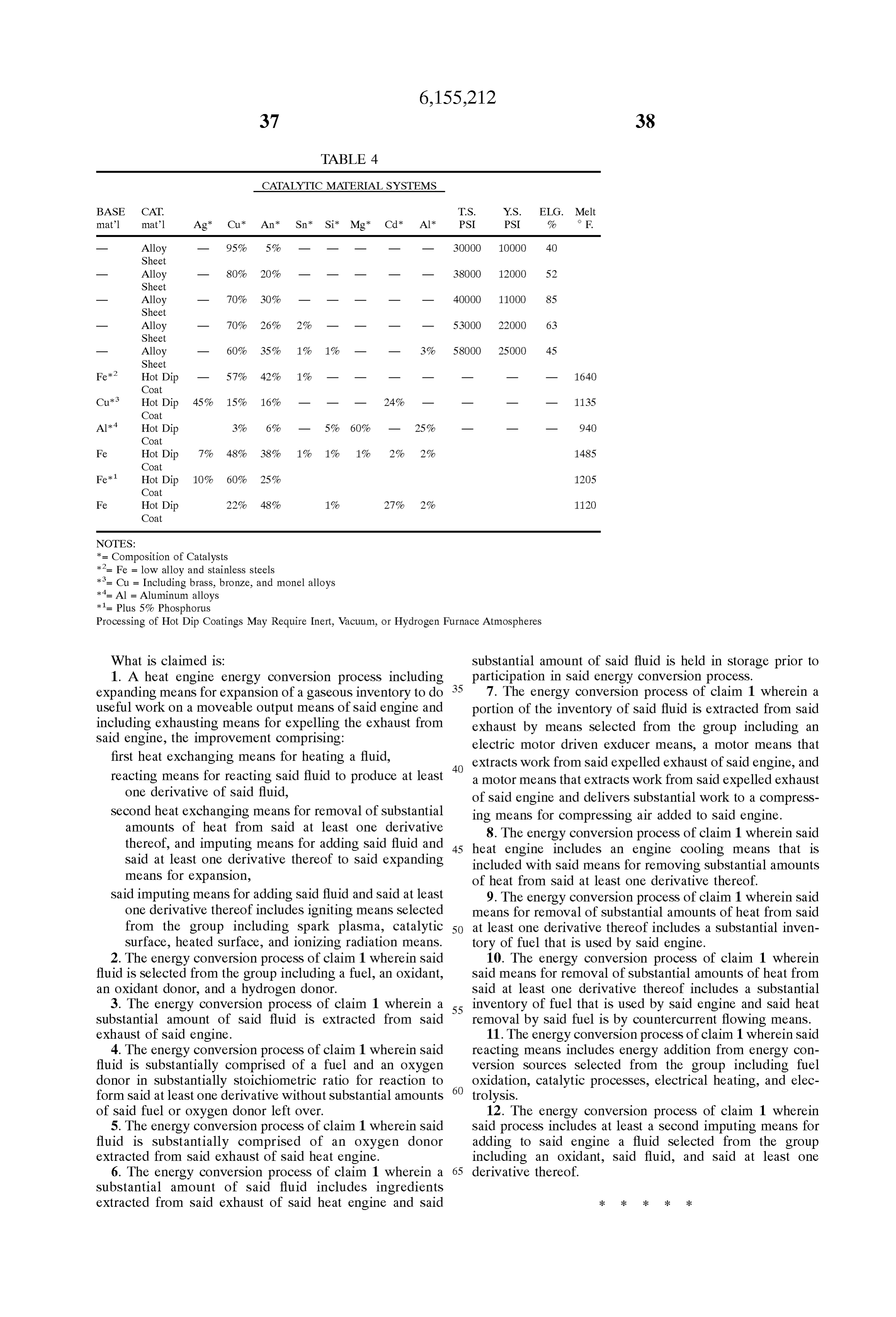
Provenance
- Collection
- Cited prior art
- Original PDF
- patentimages.storage.googleapis.com →
- Filed
- 1997-01-21
- Pages
- 27
- Method
- pdftotext (the PDF's own text layer) + pdftoppm 300dpi page scans
- Source
- Google Patents bibliographic record
- Granted
- 2000-12-05
- Inventors
- Roy E. McAlister
- Transcribed from
- patentimages.storage.googleapis.com →