patent · US3193263
Catalytic radiant heat treating apparatus
6 July 1965
Page 1
Drawing sheet — no readable text.
Page 2
United States Patent Office Patiented July 6, 1965
3,193,263 Where gas is utilized as a fuel for radiant heating
CATALYTECRADEANT HEAT TREATING apparatus, it has been common practice to burn such gas APPARATTUS in such a way that the flames impinges upon a ceramic
Richard J. Ruff, Detroit, Mich., assignor to Universai Di which is capable of withstanding exceedingly high tem Products Company, Des Plaines, Ill, a corporation of perature and such ceramic may be of the cup type or Delaware line type where the source of high temperature conse Origina application Mar 9, 1959, Ser. No. 797,935. quently takes the appearance of either a circle or a line. Divided and this application Sept. 19, 961, Ser. The source temperature of such radiant energy is ex No. 39,227 tremely high, and with proper adjustment of the air and 8 Clairas. (C. 263-8) IO gas mixture to the burner, there is no visible evidence This application is a division of my present applica of a flame, the only apparent heat source being a white tion Serial No. 797,935, fied March 9, 1959, now aban hot ceramic. Since, with this type of radiant source, the domed. source temperature must be exceedingly high, there is The present invention relates to the heat treating of no possibility of controlling the actual wave length of articles or materials and, more particularly to an im the radiant energy reaching the work. proved type of heat treating apparatus utilizing a catalytic Where gas fired radiant heat burners are utilized, it element as a source of radiant heat. is necessary to position the work being treated at a rela Heretofore, space heating as well as the heat treatment tively great distance from the burner in order to provide of articles and materials has been accomplished by the a desired degree of heat distribution and to avoid excess use of radiant heat and in most cases, the source of Such 20 heating or hot spots, and, furthermore, furnaces utilizing radiant heat has been electrically energized infra-red gas fired radiant heat burners are of necessity relatively lamps or callrod type heaters or in Some instances gas large and heavy and consequently quite costly to manu fired burners in which the heat developed by combustion facture and install.
of the gas fuel is converted to radiant heat. Gas fired radiant heat burners may be proportionately In the use of infra-red lamps as a source of radiant 25 controlled so that high or low or any intermediate energy energy, it has been common practice to utilize a large release is possible, but in order to accomplish this result, number of such lamps together with suitable reflectors the source of radiant heat remains at substantially the grouped closely together along the walls of an oven same temperature and only the size of the source increases through which the work passes and the same type of ap or decreases. This results in non-uniform diffusion of the paratus is commonly utilized with callrod heaters which 30 radiant energy where the energy released is varied and, also utilize reflectors to direct the radiant heat in a de consequently, some difficulty may be experienced in prop sired pattern. Electrically energized radiant heat sources erly treating the work subjected thereto. are relatively convenient to use and are quite effective on Radiant heat apparatus may also be used for certain certain types of work but there are several disadvantages types of cooking, such as boiling, and also this type of to this type of heater in that the surface of the heater it 35 energy may be utilized for space heating purposes, and self must be at relatively high temperature in order to the apparatus of the instant invention may be adapted for produce the desired radiant energy and, furthermore, the any of the above-mentioned uses.
reflectors must be so designed and the work must be so It is accordingly an object of the invention to provide positioned as to eliminate the possibility of producing hot a radiant heating apparatus in which a catalytic element spots on the work. Furthermore, the wave length of the 40 is utilized as the source of the radiant heat. infra-red energy is determined by the source temperature A further object of the invention is the provision of a and since a relatively high source temperature is utilized radiant heating apparatus in which a catalytic element is in order to produce a relatively large quantity of infra utilized as a source of radiant heat and in which there red energy in a reasonably small space, it is sometimes is no visible flame and in which substantially the entire difficult to provide the optimum wave length for the par radiant heat output is directed to a desired location or ticular work being treated. Furthermore, high surface area without the use of reflectors. temperatures for the heat sources result in reduced heater A still further object of the invention is the provision life and in the event a single heating unit fails, the quality of a radiant heating apparatus in which a catalytic ele of the work is adversely affected. ment is utilized as a source of radiant heat and in which Electrically energized heaters are not readily adaptable 50 means is provided for preheating the catalytic element to to proportional control since such heaters are either ignition temperature and in which means is provided for on or off, and where it is desired to secure an intermediate supplying a mixture of fuel and air to the catalytic range of radiant energy, the control of electrically ener element.
gized heaters is extremely difficult. Furthermore, re Another object of the invention is the provision of a flectors utilized with electrically energized heaters grad 55 radiant heating apparatus in which a catalytic element is ually become covered with dirt deposits thereby reducing utilized as a source of radiant heat, there being means the efficiency of the reflectors, and since less energy provided for preheating the catalytic element to ignition is reflected, more energy is absorbed with a consequent temperature and for Supplying a mixture of fuel and air increase in heat losses, and furthermore, the heat treat 60 to the catalytic element, there being also provided means ment of the work passing through the oven is adversely for preventing the supply of fuel and air when the catalytic affected by changes in heating conditions caused by dirty, element is below ignition temperature, and further control reflectors and, even under the best conditions, a sub means being provided for controlling the quantity of stantial portion of the heat released by an electrically fuel and air mixture to vary the operating temperature energized heating element is transmitted through the 65 of the catalytic element.
reflector and absorbed in the insulation or in the room. A still further object of the invention is the provision containing the oven. A further disadvantage of the elec of a radiant heating apparatus in which catalytic ele trically energized type of heater for use in radiant heat ments are utilized as a source of radiant heat and in ing is the fact that electricity usually costs from three which such elements are disposed in separate zones to seven times the cost of other fuels. As a result, it 70 through which the work may travel in order to subject will be seen that other forms of radiant heat sources such work to different heating conditions. would be desirable for many applications. Further objects and advantages of the invention will
Page 3
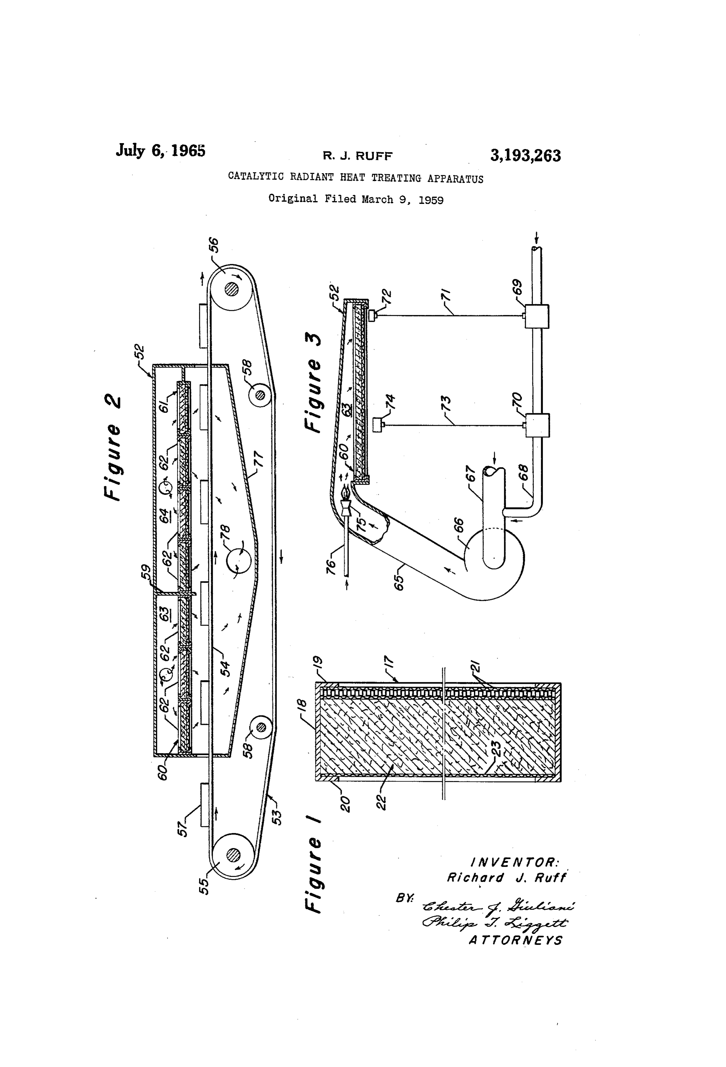
be apparent from the following description taken in con positioned adjacent the catalytic element in the radiant junction with the accompanying drawing wherein: heating unit 60 and the proportional control valve 70 FIGURE 1 is a sectional view to an enlarged scale is connected through a suitable conductor 73 to a tem showing the structure of one of the catalytic metallic perature responsive element 74 positioned in Zone 1 of the radiant heat source, walls or panels; chamber 52 and in proximity to the article 57 passing FIGURE 2 is a sectional view showing an invention through the chamber. A preheating burner 75 provided in an embodiment in which a conveyor is utilized to trans with fuel through a conduit 76 may be positioned in the port articles to be heat treated through two different heat conduit 65 in a suitable manner to supply heat to the ra treating zones; idiant heating unit 60 in order to heat the catalytic ele FIGURE 3 is an elevational view with parts in section IO ment to ignition temperature. A hood 77 may be pro for greater clarity and showing the manner of supplying vided below the upper run of the conveyor belt 54 in a gas and air mixture to the catalytic metallic element order to collect the products of combustion and the hood heat source as well as the means for preheating the cata 77 may be connected through an aperture 78 with a suit lytic element to the ignition temperature and means for able exhaust conduit.
controlling the supply of fuel and air thereto. In the operation of the above described form of the With reference to FIGURE 1, the inner wall 17 may - invention, it is assumed that articles 57 to be heat treated comprise a generally rectangular shell 8 having marginal are positioned on the conveyor belt 54 and transported inwardly extending flanges 19 and 20 and positioned with through the chamber 52 below the radiant heating units in the flange 19 and forming the inner face of the wall 17 60 and 6. The preheating burner 75 is placed in opera is an air pervious catalytic element 21. The structure of 20 tion and the catalytic element in the heating unit 60 and the catalytic element 21 may be in accordance with that also the catalytic element in the heating unit 61 are shown and described in Patent No. 2,658,742 issued No raised to ignition temperature and upon reaching such vember 10, 1953, to H. R. Suter et al., and reference is temperature, the temperature responsive element 72 oper made to this patent for a complete showing and descrip ates to open the shut-off valve 69 which results in sup tion of the catalytic element 21 and in view of this refer 25 plying fuel to the air intake conduit 67 of the blower ence, it is not considered necessary to specifically de 66 and the mixture of fuel and air is supplied through the scribe the structure of this element herein. conduit 65 to the compartment 63 above the heating unit Referring now to FIGURES 2 and 3, there is pro 60, whereupon this fuel and air mixture is burned by vided an elongated horizontal chamber 52 having a con catalytic action of the catalytic element forming the veyor 53 extending therethrough for supporting and 30 lower wall or surface of the heating element 60. The transporting articles to be heat treated. The conveyor 53 temperature within the heat treating chamber is con may be of any suitable type but for convenience of illus trolled by the temperature responsive element 74 located tration, there is shown a conveyor formed by an endless therein which operates to control the proportional valve belt 54 trained around pulleys 55 and 56 and in which 70 thereby controlling the fuel supply to the catalytic the upper run of the belt 54 passes through the chamber 35 - elements forming the heating units 60 and 61. It is, of 52 and serves to support and transport articles 57 to be course, understood that a fuel and air supply conduit heat treated in the chamber 52. The lower run of the similar to that described above is connected to the cham belt 54 may be guided by suitable pulleys or rollers 58. ber or compartment 64 above the heating unit 61 in zone A partition 59 is provided in the chamber 52 above the 2, and that the operation of the heating unit 61 is con conveyor belt 54 and the partition 59 serves to separate trolled in the same manner as described above in con the chamber 52 into different heat treating zones. While nection with the operation of heating unit 60. for convenience of illustration two heat treating zones it will therefore be seen that the entire heat output are shown, nevertheless it is to be understood that any of the radiant heating units 60 and 6 is directed down desired number of partitions may be provided in the wardly to the articles 57 passing through the chamber 52 chamber 52 to separate the same into any desired num 45 and consequently such articles will be subjected to uni ber of heat treating zones. - formly distributed radiant heat supplied by the radiant A horizontal radiant heating unit 60 is provided in zone heating units 60 and 6i, which operate to provide for 1 of the chamber 52 while a similar radiant heating unit uniform heat treatment of the articles 57 without the 61 is provided in Zone 2 of the chamber 52. The radiant presence of hot spots and also with complete control of heating units 60 and 6i are identical except for size and 50 the heating conditions.
each unit comprises a plurality of panels, 62, each panel While the various heating units utilizing catalytic ele being formed in the same manner as described above and ments have been described as being generally rectangular shown in detail in FIGURE 1, the lower wall or surface and flat, it is of course understood that these units may being provided by a catalytic element above which there be made in other shapes and also may be curved or is disposed a layer of wool-like material, and such layer 55 formed in various configurations to correspond with the being held in place by a backing screen, all as described configuration of the material or articles being heat treated. above in connection with FIGURE 1. Any number of Also for convenience, the above description has dealt panels 62 may be provided in the heating zones to supply with the heat treatment of articles but obviously the same the required heat output over the necessary surface area. principles of construction may be utilized to provide radi ant heat sources for cooking purposes and also for space
A closed compartment 63 is provided within the cham 60 heating.
ber 52 above the radiant heating unit 60 in zone 1, and in It will be obvious to those skilled in the art that various a similar manner, a closed compartment 64 is provided changes may be made in the invention without departing within the chamber 52 above the radiant heating unit 61 from the spirit and scope thereof, and therefore the inven in zone 2. As best shown in FIGURE 3, a conduit 65 65 tion is not limited by that which is shown in the drawings communicates with the compartment 63 and the opposite and described in the specification. end of the conduit 65 is connected to the output of a I claim as my invention:
blower 66 or other suitable source of air pressure. An 1. A catalytic radiant heat treating apparatus compris air inlet conduit 67 is provided for the blower 66 and ing an elongated horizontal chamber, means in said cham connected to the inlet conduit 67 is a fuel supply conduit ber for supporting articles to be heat treated, a substan 68 provided with an automatically operable temperature 70 tially horizontal flameless and catalytic radiant heating controlled shut-off valve 69 and also an automatically unit spaced above and disposed in heat radiating relation operable temperature controlled proportional valve 70. to said supporting means, said unit including a lower wall Shut-off valve 69 may be connected through a suitable formed by an air pervious catalytic element providing a conductor 71 with a temperature responsive element 72 75 Source of radiant heat and a layer of air diffusing material
Page 4
S 6 covering the upper surface of said catalytic element, a air diffusing material covering the upper surface of said closed compartment above said unit and communicating catalytic element, a closed compartment above said unit with said catalytic element through said layer, a conduit and communicating with said catalytic element through communicating with said compartment, means for Sup said layer, a conduit communicating with said compart plying air under pressure to said conduit, means for pre ment, means for supplying air under pressure to said heating the catalytic element to ignition temperature, and conduit, a preheating burner disposed in said conduit for a fuel supply connected to said conduit, whereby articles preheating the catalytic element to ignition temperature, on said supporting means will be heat treated by radiant a fuel supply connected to said conduit, an automatically heat emanating from saidi fiammeless catalytic element. operable shut-off valve in the fuel Supply to said conduit, 2. A catalytic radiant heat treating apparatus compris O temperature responsive elements adjacent the catalytic ing an elongated horizontai chamber, means in said cham element and operable to open said shut-off valve upon ber for Supporting articles to be heat treated, a Substan said catalytic element reaching ignition temperature and tially horizontal flameless and catalytic radiant heating to close said shut-off valve upon the temperature of the unit spaced above and disposed in heat radiating relation catalytic element falling below ignition temperature, an to said supporting means, said unit including a lower wall 5 automatically operable control valve in the fuel supply formed by an air pervious catalytic element providing a to said conduit and temperature responsive elements ad source of radiant heat and a layer of air diffusing material jacent said conveyor for controlling the operation of said covering the upper surface of said catalytic element, a control valve to control the supply of fuel to the catalytic closed compartment above said unit and communicating element in accordance with the temperature, whereby ar with said catalytic element through said layer, a conduit 20 ticles carried by said conveyor will be heat treated by ra communicating with said compartment, means for Sup diant heat emanating from said flameless catalytic elle plying air under pressure to said conduit, means for pre ment.
heating the catalytic element to ignition temperature, a 5. A catalytic radiant heat treating apparatus compris fuel supply connected to said conduit, an automatically ing an elongated horizontal chamber, a conveyor extend operable shut-off valve in the fuel supply to said conduit, ing through said chamber for supporting and transport temperature responsive elements adjacent the catalytic ing articles to be heat treated, a horizontal flameless and element and operable to open said shut-off valve upon catalytic radiant heating unit disposed above and disposed said catalytic element reaching ignition temperature and in heat radiating relation to said conveyor, said unit to close said shut-off waive upon the temperature of the comprising a plurality of panels, each panel including a catalytic element falling below ignition temperature, an 30 lower wall formed by an air pervious catalytic element automatically operable control valve in the fuel supply providing a source of radiant heat and a layer of air to said conduit and temperature responsive elements adja diffusing material covering the upper surface of said cent said supporting means for controlling the operation catalytic element, a closed compartment above said panels of said control valve to control the supply of fuel to the and communicating with said catalytic elements through catalytic element in accordance with the temperature, 35 said layers, a conduit communicating with said compart whereby articles on said supporting means will be heat ment, means for supplying air under pressure to said con treated by radiant heat emanating from said flameless duit, a preheating burner disposed in said conduit for catalytic element. m preheating the catalytic elements to ignition temperature, 3. A catalytic radiant heat treating apparatus compris a fuel supply connected to said conduit, an automatically ing an elongated horizontal chamber, a conveyor extend 40 operable shut-off valve in the fuel supply to said conduit, ing through said chamber for supporting and transporting temperature responsive elements adjacent the catalytic articles to be heat treated, a horizontal fameless and elements and operable to open said shut-off valves upon catalytic radiant heating unit spaced above and disposed said catalytic elements reaching ignition temperature and in heat radiating relation to said conveyor, said unit in to close said shut-off valves upon the temperature of the cluding a lower wall formed by an air pervious catalytic 45 catalytic elements falling below ignition temperature, an element providing a source of radiant heat and a layer automatically operable control valve in the fuel supply to of air diffusing material covering the upper surface of said conduit and temperature responsive elements adja said catalytic element, a closed compartment above said cent said conveyor for controlling the operation of said unit and communicating with said catalytic element control valves to control the supply of fuel to the catalytic through said layer, a conduit communicating with said 50 elements in accordance with the temperature, whereby ar compartment, means for Supplying air under pressure to ticles carried by said conveyor will be heat treated by said conduit, means for preheating the catalytic element radiant beat emanating from said flameless catalytic elle to ignition temperature, a fuel supply connected to said eiliS.
conduit, an automatically operable shut-off valve in the 6. A catalytic radiant heat treating apparatus compris fuel Supply to said conduit, temperature responsive ele 55 ing an elongated horizontal chamber, a conveyor extend ments adjacent the catalytic element and operable to open ing through said chamber for supporting and transport said shut-off valve upon said catalytic element reaching ing articles to be heat treated, a partition in said cham ignition temperature and to close said shut-off valve upon ber above said conveyor providing first and second heat the temperature of said catalytic element falling below treating zones, a horizontal flameless and catalytic radiant ignition temperature, an automatically operable control 60 heating unit in each zone spaced above and disposed in valve in the fuel supply to said conduit and temperature heatradiating relation to Said conveyor, each unit compris responsive elements adjacent said conveyor for control ing a piurality of panels, each panel including a lower ling the operation of said control valve to control the wall formed by an air pervious catalytic element provid Supply of fuel to the catalytic element in accordance with ing a source of radiant heat and a layer of air diffusing the temperature, whereby articles carried by said con 65 material covering the upper surface of said catalytic ele veyor will be heat treated by radiant heat emanating from ment, a closed compartment in each zone above said said flameless catalytic element. panels and communicating with said catalytic elements 4. A catalytic radiant heat treating apparatus compris through said layers, a conduit communicating with said ing an elongated horizontal chamber, a conveyor extend first compartment and a second conduit communicating ing through said chamber for supporting and transport O with said second campartment, means for supplying air ing articles to be heat treated, a horizontal flameless and under pressure to each conduit, a preheating burner dis catalytic radiant heating unit spaced above and disposed posed in each conduit for preheating the catalytic ele in heat radiating relation to said conveyor, said unit in ments in each Zone to ignition temperature, a fuel supply cluding a lower wall formed by an air pervious catalytic connected to each conduit, an automatically operable shut element providing a source of radiant heat and a layer of 5 off valve in the fuel Supply to each conduit, temperature
Page 5
7 -3 responsive elements in each zone adjacent the catalytic ele ing through said chamber for supporting and transport ments and operable to open said shut-off valves upon ing articles to be heat treated, a partition in said chamber said catalytic elements reaching ignition temperature and above said conveyor providing first and second heat treat to close said shut-off valves upon the temperature of the ing zones, a horizontal flameless and catalytic radiant catalytic elements falling below ignition temperature, an heating unit in each Zone spaced above and disposed in automatically operable control valve in the fuel supply heat radiating relation to said conveyor, each unit com to each conduit and temperature responsive elements in prising a plurality of panels, each panel including a lower each zone for controlling the operation of said control wall formed by an air pervious catalytic element provid valves to control the supply of fuel to the catalytic ele ing a source of radiant heat, a layer of air diffusing wool ments in accordance with the temperature in each Zone, 10 like flameproof material covering the upper surface of said whereby articles carried by said conveyor will be heat catalytic element and a screen covering the upper surface treated by radiant heat emanating from said flameless of said layer to retain the same in place, a closed compart catalytic elements. ment in each Zone above said panels and communicating 7. A catalytic radiant heat treating apparatus compris with said catalytic elements through said screens and said ing an elongated horizontal chamber, a conveyor extend 15 layers, a conduit communicating with said first compart ing through said chamber for supporting and transport ment and a second conduit communicating with said sec ing articles to be heat treated, a partition in said chamber ond compartment, means for supplying air under pressure above said conveyor providing first and second heat treat to each conduit, a preheating burner disposed in each con ing zones, a horizontal fiameless and catalytic radiant duit for preheating the catalytic elements in each zone to heating unit in each zone spaced above and disposed in 20 ignition temperature, a fuel Supply connected to each con heat radiating relation to said conveyor, each unit com duit, an automatically operable shut-off valve in the fuel prising a plurality of panels, each panel including a lower - Supply to each conduit, temperature responsive elements in wall formed by an air pervious catalytic element provid each zone adjacent the catalytic elements and operable to ing a source of radiant heat and a layer of air diffusing open said shut-off valves upon said catalytic elements wool-like flameproof material covering the upper surface 25 reaching ignition temperature and to close said shut-off of said catalytic element, a closed compartment in each valves upon the temperaure of the catalytic elements zone above said panels and communicating. With said falling below ignition temperature, an automatically catalytic elements through said layers, a conduit con operable control valve in the fuel supply to each conduit municating with said first compartment and a second con and temperature responsive elements in each zone for con duit communicating with said second compartment, means 30 trolling the operation of said control valves to control the for supplying air under pressure to each conduit, a pre Supply of fuel to the catalytic elements in accordance heating burner disposed in each conduit for preheating with the temperature in each zone, whereby articles car the catalytic elements in each zone to ignition tempera ried by said flameless conveyor will be heat treated by ture, a fuel supply connected to each conduit, an auto radiant heat emanating from said catalytic elements. matically operable shut-off valve in the fuel supply to 35 References Cited by the Examiner each conduit, temperature responsive elements in each zone adjacent the catalytic elements and operable to open UNITED STATES PATENTS said shut off valves upon said catalytic elements reaching 1,213,470 1/17 Finlay -------------- 158- 99 ? ignition temperature and to close said shut-off valves 40 1,469,178 9/23 Ellis.
upon the temperature of the catalytic elements falling be 2,218,354 10/40 Keller.------------------ 263-3 low ignition temperature, an automatically operable con 2,558,493 6/51 Melot -------------- 158- 96 X trol valve in the fuel supply to each conduit and tempera 2,658,742 11/53 Suter et al. --------- 158-96 X ture responsive elements in each Zone for controlling the 2,668,701 2/54 Dietrich ---------------- 263-3 operation of said control valves to control the supply of 45 3,022,987 3/59 Thorsheim ---------- 263-33 X fuel to the catalytic elements in accordance with the - FOREIGN PATENTS temperature in each zone, whereby articles carried by said conveyor will be heat treated by radiant heat emanat 992,224 10/51 . France... - ing from said flameless catalytic elements. CHARLES SUKALO, Primary Examiner. 8. A catalytic radiant heat treating apparatus compris ing an elongated horizontal chamber, a conveyor extend 50 PERCY L. PATRICK, Examiner.
Provenance
- Collection
- Cited prior art
- Original PDF
- patentimages.storage.googleapis.com →
- Filed
- 1961-09-19
- Pages
- 5
- Method
- pdftotext (the PDF's own text layer) + pdftoppm 300dpi page scans
- Source
- Google Patents bibliographic record
- Granted
- 1965-07-06
- Inventors
- Richard J Ruff; Universal Oil Products Co
- Transcribed from
- patentimages.storage.googleapis.com →