patent · US6101821
Ice thermal storage coil systems and methods
15 August 2000
Page 1 — bibliographic record
United States Patent (19) 11 Patent Number: 6,101,821 Cates (45) Date of Patent: Aug. 15, 2000 54 ICE THERMAL STORAGE COIL SYSTEMS Baltimore Aircoil Company Bulletin S150/1-OBA, entitled AND METHODS “Ice Chiller(R) Thermal Storage Products for Use with Glycol Chillers,” Cover Sheet and 24 pages, (Jan. 1995).
75 Inventor: Robert E. Cates, Kingwood, Tex. Baltimore Aircoil Company Bulletin S155/1-OBA, entitled 73 Assignee: Evapco International, Inc., “Ice Chiller Thermal Storage Units,” Cover Sheet and 7 Wilmington, Del. pages (1997).
Calmac Manufacturing Corporation Bulletin entitled “An
Introduction to Ice Bank Sotred Cooling Systems for Com 21 Appl. No.: 09/316,404 mercial Air Conditioning Applications,” W.G. Dockendorf, 22 Filed: May 21, 1999 Inc., Ed., 6 pages (1982). York International Corporation, Applied Systems, Brochure
Related U.S. Application Data entitled “York(E) ICEPAKTM SC-Self Contained Thermal 60 Provisional application No. 60/086,490, May 22, 1998. Storage System,” Form 175,00-EG1, Cover Sheet and pp. (51) Int. Cl. .................................................. F25D 3700 10–14 (1988).
52 U.S. C. ... . . 62/139; 62/59 FAFCO, Inc. Brochure P/N 06438 entitled “IceStorTM Advanced Technology Cool Storage Systems,” Cover Sheet 58 Field of Search ................................ 62/59, 515, 139; and 6 pages (1997).
165/150, 151,163 Perma-Pipe Brochure entitled “On the Job with Per 56) References Cited ma-IceTM,” vol. 2, #1, 4 pages, (1985).
2,056,970 10/1936 Leopold .................................... 62/139 Primary Examiner William E. Tapolcai 3,197.975 8/1965 Boling ....................................... 62/515 Attorney, Agent, Or Firm Akin, Gump, Strauss, Hauer & 3,484.805 12/1969 Lorenz ...................................... 62/139 4,192,146 3/1980 Crede .......................................... 62/59 Feld, L.L.P.
4.294,078 10/1981 MacCracken. 57 ABSTRACT
4,609,036 9/1986 Schrader. The present invention is directed toward an ice-on-coil 4,616,390 10/1986 MacCracken. (IOC) thermal Storage coil system and method utilizing 4,671,347 6/1987 MacCracken. “deep-tank” technology and dimensional relationship of coil 4,831,831 5/1989 Carter et al.. height to coil width wherein the coil Serpentine's height
5,596,877 1/1997 Morrison. (vertical tube dimension) is greater than the width (the 5,598,720 2/1997 MacCracken et al.. horizontal dimension), and wherein all manifold and header 5,649,431 7/1997 Schroeder, Jr.. joints are above, or just below the water Surface of the tank,
OTHER PUBLICATIONS
easily visible and accessible for maintenance, assembly, leak-checking or repair. Another aspect of the present ice
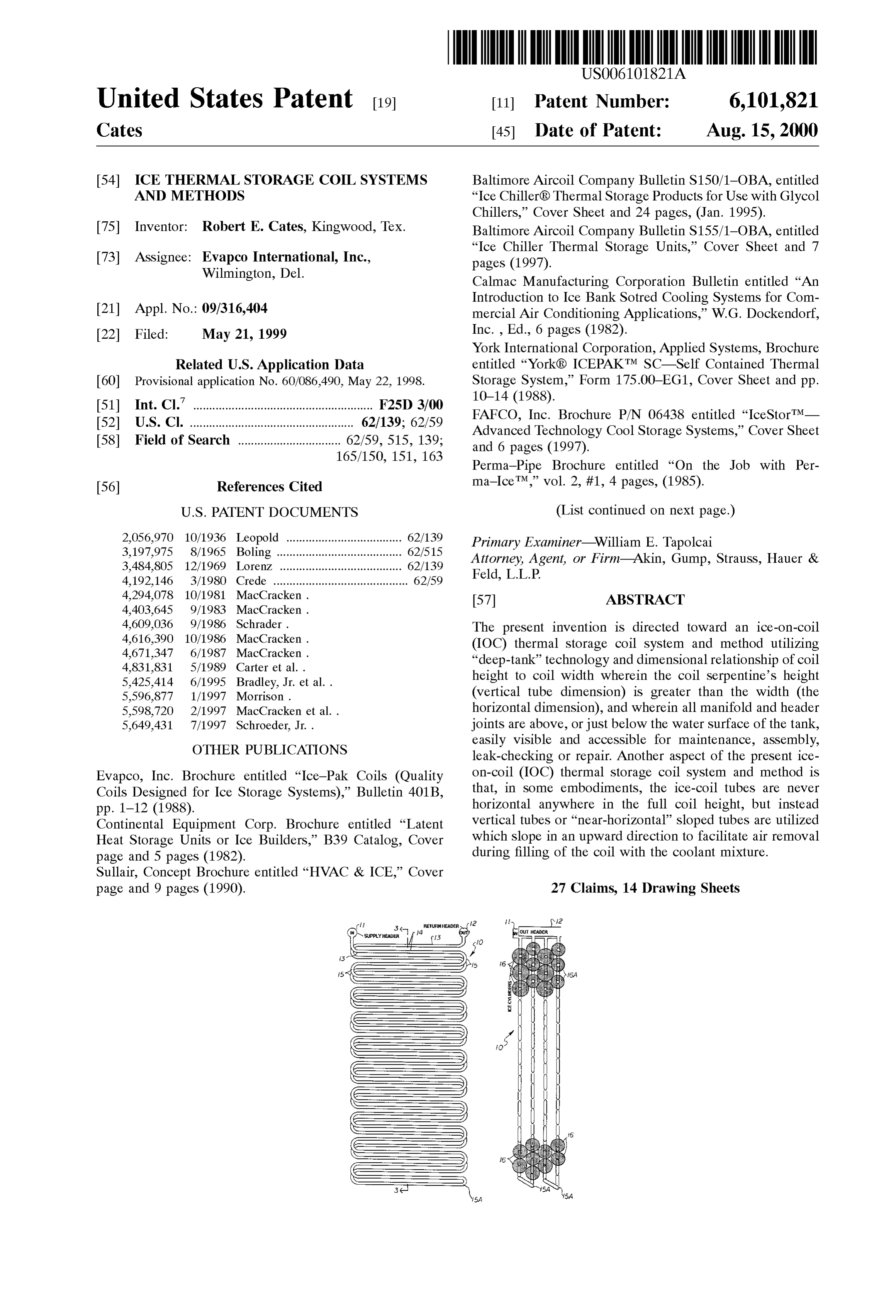
Evapco, Inc. Brochure entitled “Ice-Pak Coils (Quality on-coil (IOC) thermal storage coil System and method is Coils Designed for Ice Storage Systems).” Bulletin 401B, that, in Some embodiments, the ice-coil tubes are never pp. 1-12 (1988). horizontal anywhere in the full coil height, but instead Continental Equipment Corp. Brochure entitled “Latent vertical tubes or “near-horizontal” Sloped tubes are utilized Heat Storage Units or Ice Builders,” B39 Catalog, Cover which Slope in an upward direction to facilitate air removal page and 5 pages (1982). during filling of the coil with the coolant mixture. Sullair, Concept Brochure entitled “HVAC & ICE,” Cover page and 9 pages (1990). 27 Claims, 14 Drawing Sheets
YSUPPY HEADF3 f Eurtain
Reeses
are is
(SES
lsA
Page 2
OTHER PUBLICATIONS Baltimore Aircoil Co. Brochure #S156/1-OCA, entitled “Ice Chiller Thermal Storage Unit-Application Guide”, Cover
Perma-Pipe Brochure entitled “Bundles of Ice That Save Sheet and p. 6 (unknown).
You Bundles of Money,” 3 pages (1987). Brady, Thomas W., “Thermal Storage for the Merchandise Chester-Jensen Company Catalog entitled “Air Agitated Ice
Builders,” Catalog Section M, Cover Sheet, pp. M1-M7 & Mart.” Ashrae Journal, 5 pages (Nov. 1986). 1 additional page (1983). “The Role of Stainless Steel in Industrial Heat Exchangers,” IMECO Inc. advertisement, p. 17, Ashrae Journal (May Brochure of Committee of Stainless Steel Producers, Ameri 1985). can Iron and Steel Institute, Washington, DC 20036, Cover Chester-Jensen Company Incorporated, Drawing No. C-J Sheet and 4 pages (Apr. 1976).
Dec. 9, 1983 for XM-16-12-100 Ice Builder. Kern, Donald Q., “Process Heat Transfer.” McGraw-Hill Baltimore Aircoil Co. Brochure entitled “Ice Chiller Ther Book Company, Cover Sheet and p. 135 (1950). mal Storage Units-Featuring A High Efficiency Coil J. Gregory Reardon, P.E. and Kenneth M. Penuel, “Thermal Design for Lower System Operating Cost,” Cover Sheet and Storage -An ice-making showcase, Ashrae Journal, pp. 2, 3, 9, 10 & 11 (1985). Cover Sheet and 6 pages (May 1985).
Page 3
Drawing sheet — no readable text.
Page 4
Drawing sheet — no readable text.
Page 5
Drawing sheet — no readable text.
Page 6
Drawing sheet — no readable text.
Page 7
Drawing sheet — no readable text.
Page 8
Drawing sheet — no readable text.
Page 9
Drawing sheet — no readable text.
Page 10
Drawing sheet — no readable text.
Page 11
Drawing sheet — no readable text.
Page 12
Drawing sheet — no readable text.
Page 13
Drawing sheet — no readable text.
Page 14
Drawing sheet — no readable text.
Page 15
Drawing sheet — no readable text.
Page 16
Drawing sheet — no readable text.
Page 17
ICE THERMAL STORAGE COIL SYSTEMS the inlet or outlet connections of the coil module. The coil AND METHODS tubes are more likely to leak at the field piping or header joints than any other area, even after galvanizing. The
CROSS REFERENCE TO RELATED present invention provides an accessible tube option to APPLICATION isolate as few as two tubes at the top, without losing any This application claims priority of U.S. Provisional Appli Significant ice-making capacity, Should a leak occur in a tube circuit.
cation Ser. No. 60/086,490, filed May 22, 1998. The present invention is distinguished over the prior art in BACKGROUND OF THE INVENTION general, by an ice-on-coil (IOC) thermal storage coil system and method utilizing “deep-tank” technology and dimen 1. Field of the Invention sional relationship of coil height to coil width wherein the This invention relates generally to apparatus and methods coil Serpentine's height (vertical tube dimension) is greater that utilize an “ice-on-coil” (IOC) thermal storage than the width (the horizontal dimension), and wherein all technique, as opposed to other methods of thermal Storage, manifold and header joints are above, or just below the water and more particularly to ice thermal Storage coil Systems and 15 Surface of the tank, easily visible and accessible for methods for use in “ice-on-coil” (IOC) installations. maintenance, assembly, leak-checking or repair. Another 2. Brief Description of the Prior Art aspect of the present ice-on-coil (IOC) thermal storage coil Current “ice-on-coil” (IOC) thermal storage methods use System and method is that, in Some embodiments, the either coils formed of plastic tubes or galvanized Steel tubes ice-coil tubes are never horizontal anywhere in the full coil in bundled modules. Major suppliers of IOC thermal storage height, but instead vertical tubes or “near-horizontal' sloped systems include: Baltimore Aircoil Co. of Jessup, Md., tubes are utilized which slope in an upward direction to Evapco, Inc. of Westminster, Md. (steel tubes), Calmac coolant facilitate air removal during filling of the coil with the Manufacturing Corp. of Englewood, N.J., and Fafico, Inc. of mixture.
Redwood City, Calif. (plastic tubes). The art of each 25 SUMMARY OF THE INVENTION involves methods of circuiting the coil modules to best achieve even ice-build and melt processes, and to best It is therefore an object of the present invention to provide manage the air removal during glycol-filling and draining an ice-on-coil (IOC) thermal Storage coil system and method processes. However, each has major draw-backs which are which may be used on any large or Small air conditioning or difficult to manage economically when projected to the process cooling System where the very Smallest floor-space larger capacity Systems where many modules are connected requirement is a necessity, it may be best used where current in parallel or installed in deep tanks where it is desired to ice coils are Stacked-up in deeper tanks, Such as installations minimize the floor Space used for the water-filled Storage used for larger office building air conditioning Systems that tanks which contain the coil modules. These State-of-the-art use thermal storage, or for “District Cooling thermal stor Systems require massive welded piping and manifolds below 35 age Systems or other large buildings requiring air condition the waterline of the ice Storage tanks to facilitate piping ing with ice thermal Storage.
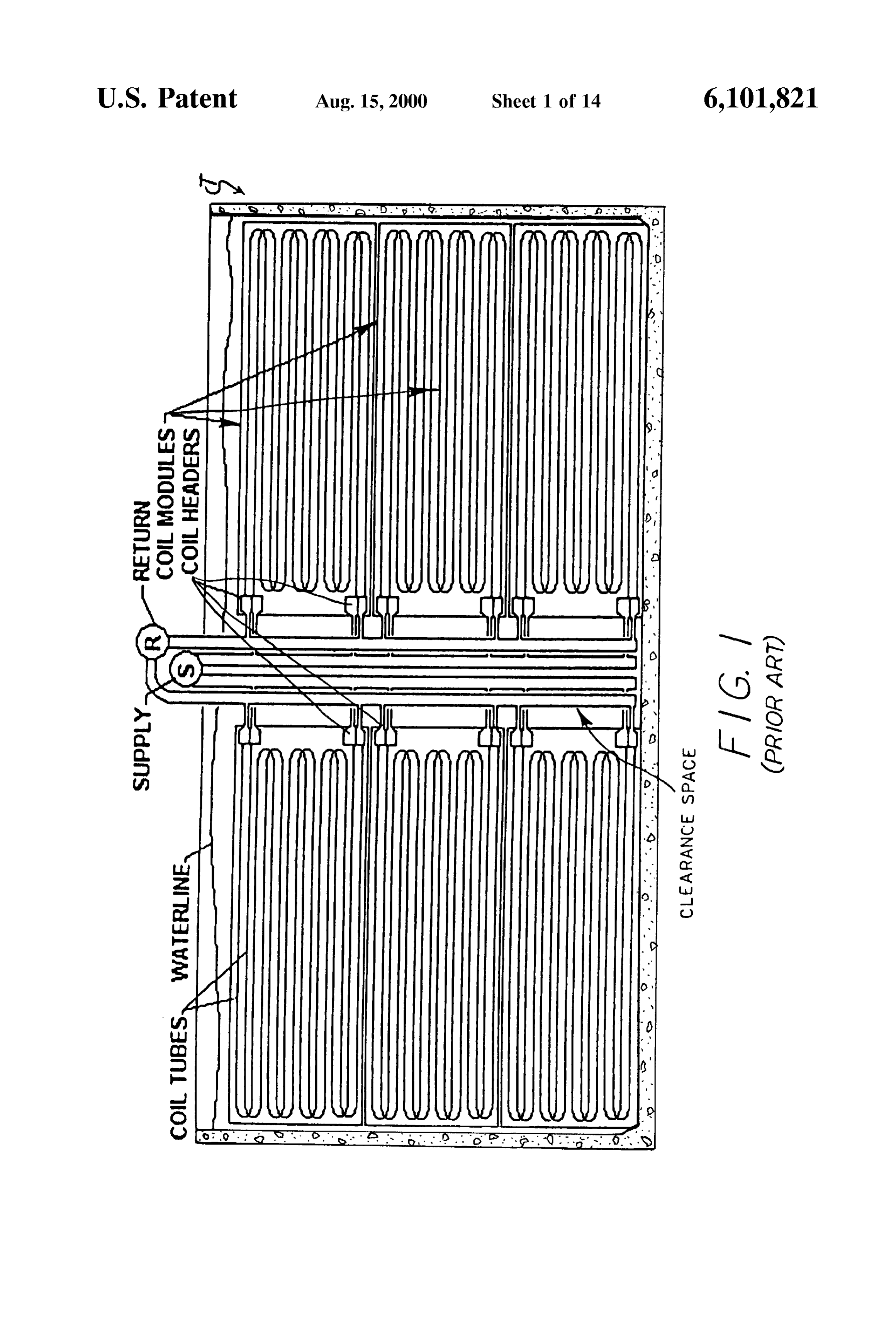
connections to each module of the Stacked module group It is another object of this invention to provide an ice ings and to achieve the reverse-piping arrangements to on-coil (IOC) thermal storage coil System and method Successfully remove air during filling with the glycol-water utilizing “deep-tank” technology and dimensional relation refrigerant inside the coil tubes. 40 ship of coil height to coil width wherein the coil serpentine's FIG. 1 is an example of a typical Serpentine "ice-on-coil” height (vertical dimension) is greater than the width System of the current State-of-the-art, or prior art. AS shown (horizontal dimension), and in Some installations at least in FIG. 1, the Serpentine coil modules are at least 2 times as twice as high as the tube circuit width between the U-bends. wide as they are high. In the real applications of these prior Another object of this invention is to provide an ice-on art coils, the Serpentines are typically up to 7" high by 21' 45 coil (IOC) thermal storage coil system and method utilizing wide per module. Some are even less than 7" high by 21 “deep-tank” technology and dimensional relationship of coil wide, and in the case of Smaller prior art coil modules, the height to coil width wherein the coil Serpentine module units are typically 4' high by 12' wide. height and width are designed to be accommodated in The prior art typically uses a Stack of two to Six deep coil conventional galvanizing tanks and on the beds of Shipping modules, and presents many problems during construction 50 trucks of Standard dimensional size.
to actually provide a Space Sufficient to complete the piping Another object of this invention is to provide an ice-on installation with Suitable acceSS space for welders down coil (IOC) thermal storage coil system and method which deep in the tank between the coil modules. This welding may be utilized in larger Systems, Such as “District Cooling” access and lost piping Space also requires the tank to be IOC plants, wherein a special downtown icemaking plant is larger than required. The present invention eliminates the 55 established, in cooperation with the local utility, and the major problem of tight working Spaces for welding the plant provides ice water or glycol through underground manifold connections and piping in the deep tanks and piping to the individual buildings of a Sector of the city to allows use of a Smaller tank for the same total thermal provide the necessary air conditioning, thereby eliminating Storage capacity requirement. the need for the building to provide air conditioning Prior art steel tubes used for the coils are typically welded 60 compressors, condensers, and cooling towers, etc. on-line as they are manufactured by roll-forming from thin Another object of this invention is to provide an ice-on strips of sheet steel. These tubes are then formed to about coil (IOC) thermal storage coil system and method which 180 degree U-bends as they make up a Serpentine, then the may be utilized in “District Cooling” IOC plants, which will Serpentines are Stacked in a Spaced frame to form a complete allow a given building to remove obsolete equipment which coil module and are further welded at the tube ends to a 65 otherwise might require expensive re-building to achieve the drilled or punched header plate. The header plates are then required up-grading to meet CFC environmental regulations, enclosed by a welded channel to form a closed manifold for and permits more energy efficient concepts which shift load
Page 18
off the utility in peak-load periods to allow use of generated dimension), and wherein all manifold and header joints are electric power at night when least expensive to build ice for above, or just below the water Surface of the tank, easily melting during the next day's peak periods. Visible and accessible for maintenance, assembly, leak Another object of this invention is to provide an ice-on checking or repair. Another aspect of the present ice-on-coil coil (IOC) thermal storage coil system and method which (IOC) thermal Storage coil system and method is that, in may be utilized in “District Cooling” IOC plants, which will Some embodiments, the ice-coil tubes are never horizontal allow a building owner to restore the floor Space previously anywhere in the full coil height, but instead vertical tubes or used for mechanical equipment to productive use, Such as a “near-horizontal” Sloped tubes are utilized which slope in an retail or office Space. upward direction to facilitate air removal during filling of the coil with the coolant mixture.
Another object of this invention is to provide an ice-on coil (IOC) thermal storage coil system and method which BRIEF DESCRIPTION OF THE DRAWINGS may be utilized in high, round or rectangular tanks and in
Smaller installations where only a very Small floor-space is FIG. 1 is a Schematic croSS Sectional view of a typical available, Such as in corners of alley-ways of high-rise 15 deep-tank Stacked module ice-coil Serpentine arrangement buildings, or where only a portion of a building might be of the prior art.
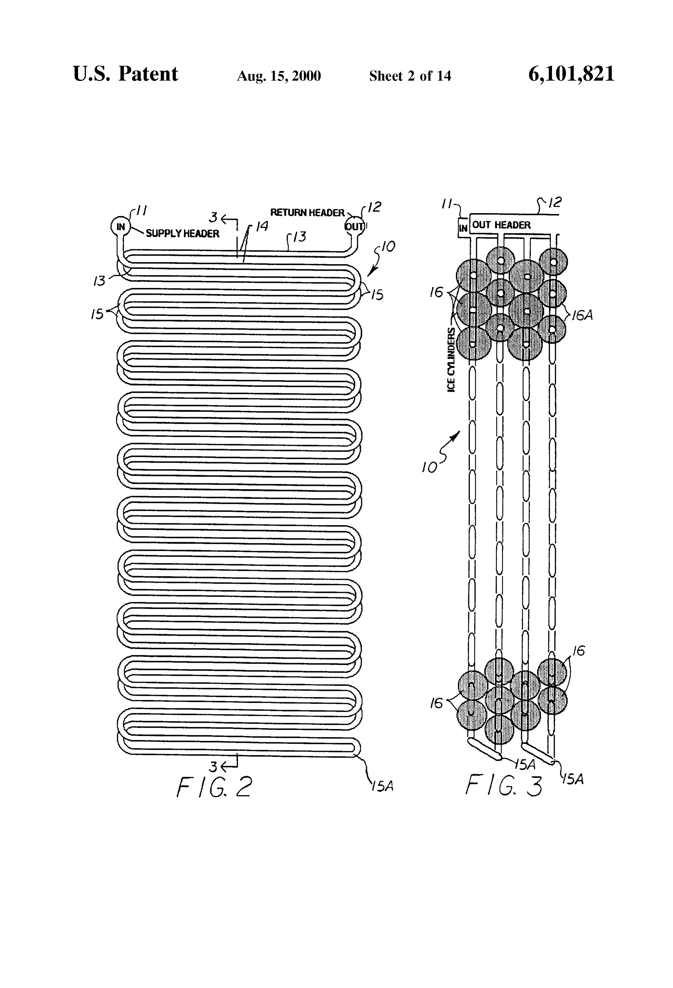
available for thermal Storage, Such as a night club or FIG. 2 is a schematic side elevation of a typical tall restaurant which may need special cooling provided to non-Stack deep-tank ice-coil Serpentine module in accor augment an old air conditioning System. dance with the present invention, shown with the ice cylin Another object of this invention is to provide an ice-on derS and framing details omitted.
coil (IOC) thermal storage coil system and method wherein FIG. 3 is a schematic cross section taken along line 3-3 all manifold and header joints are above, or just below the of FIG. 2, showing how adjacent ice cylinders are nested in water Surface of the tank, easily visible and accessible for a pattern of least Void space, when placed in the tank and maintenance, assembly, leak-checking or repair, and water is frozen on the tubes.
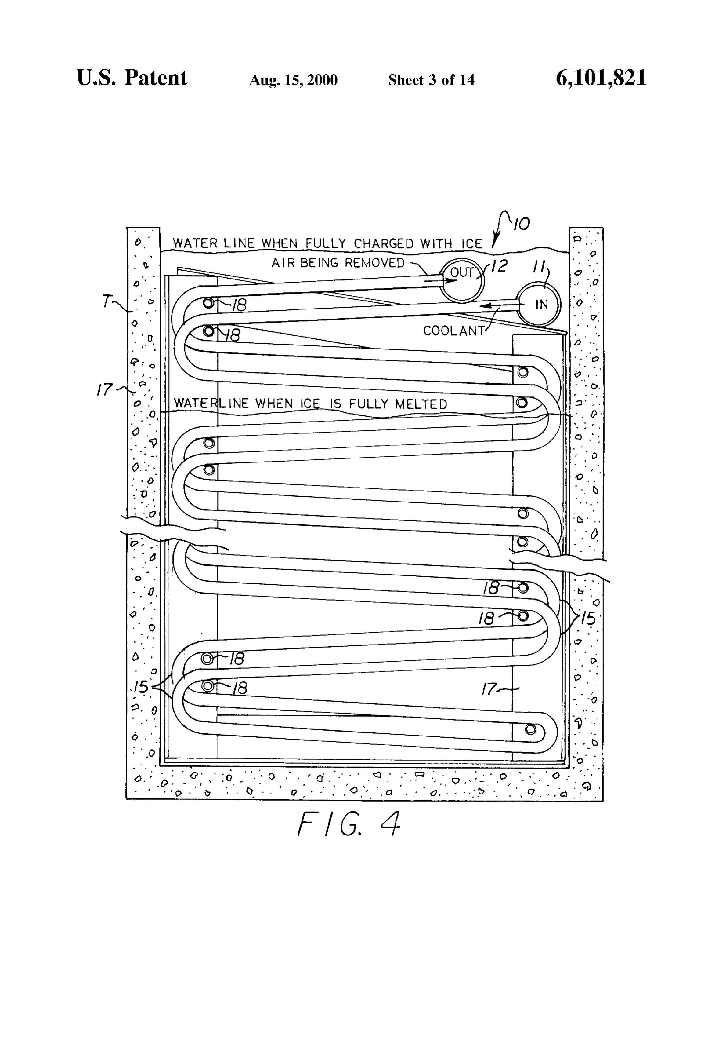
wherein mainly the tubes are Submerged for ice-building 25 FIG. 4 is a schematic side elevation of the tall non-stack purposes. deep-tank ice-coil Serpentine module in accordance with the Another object of this invention is to provide an ice-on present invention, showing one preferred header and Sloped coil (IOC) thermal storage coil system and method which tube coil module construction.
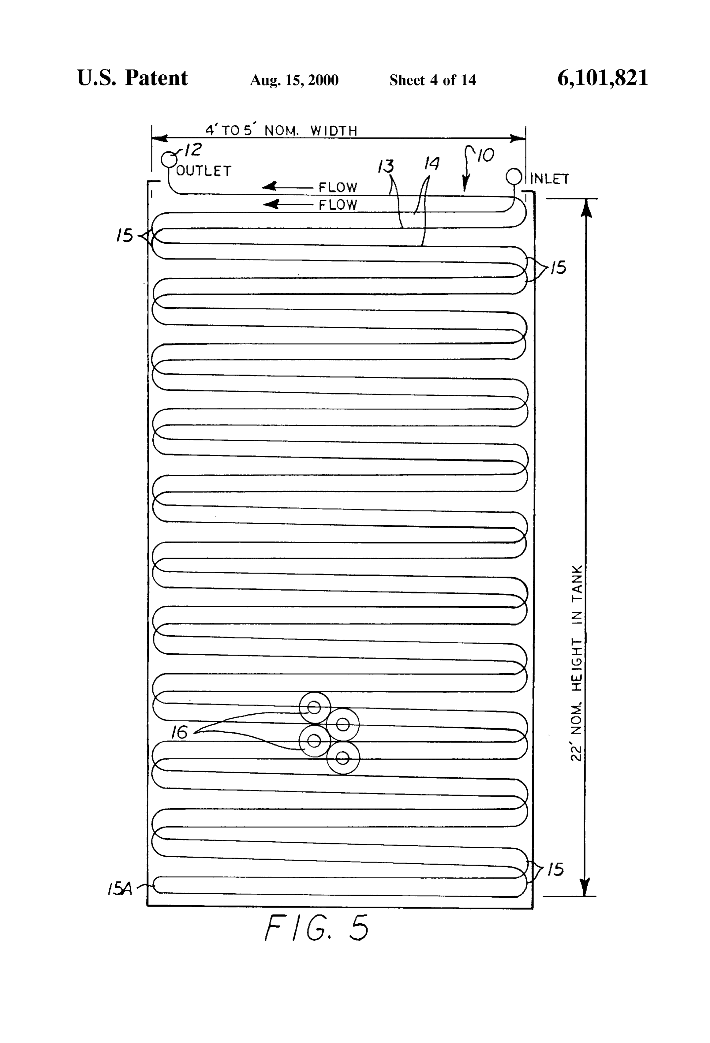
has an accessible tube option that allows as few as two tubes FIG. 5 is a schematic side elevation of the tall non-stack at the top to be isolated without losing any significant deep-tank ice-coil Serpentine module in accordance with the ice-making capacity, should a leak occur in a tube circuit. present invention, representing the coil tubes (shown in Another object of this invention is to provide an ice-on Single line) inside a water tank and illustrating the height to coil (IOC) thermal storage coil system and method wherein horizontal width relationship.
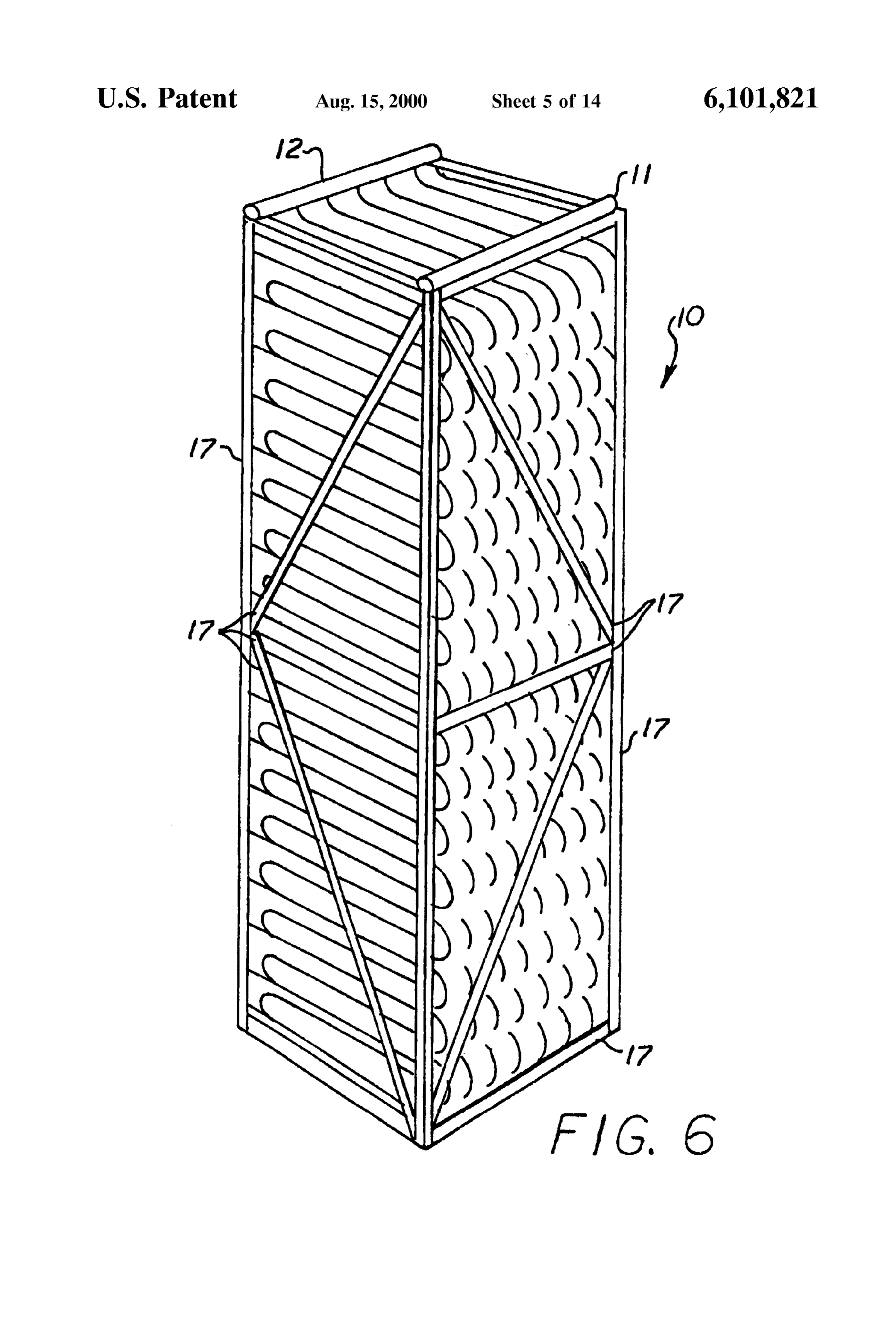
the ice-coil tubes are never horizontal anywhere in the full FIG. 6 is a Schematic perspective view of a typical tall coil height, but instead utilizes vertical tubes or “near 35 non-Stack deep-tank ice-coil Serpentine modular package in horizontal” tubes which slope in an upward direction to accordance with the present invention which allows han facilitate air removal during filling of the coil with glycol dling and shipping (typically in the horizontal position) and Water. the shape of the module as it is to be inserted into the deep Another object of this invention is to provide an ice-on tank (in the vertical position shown).
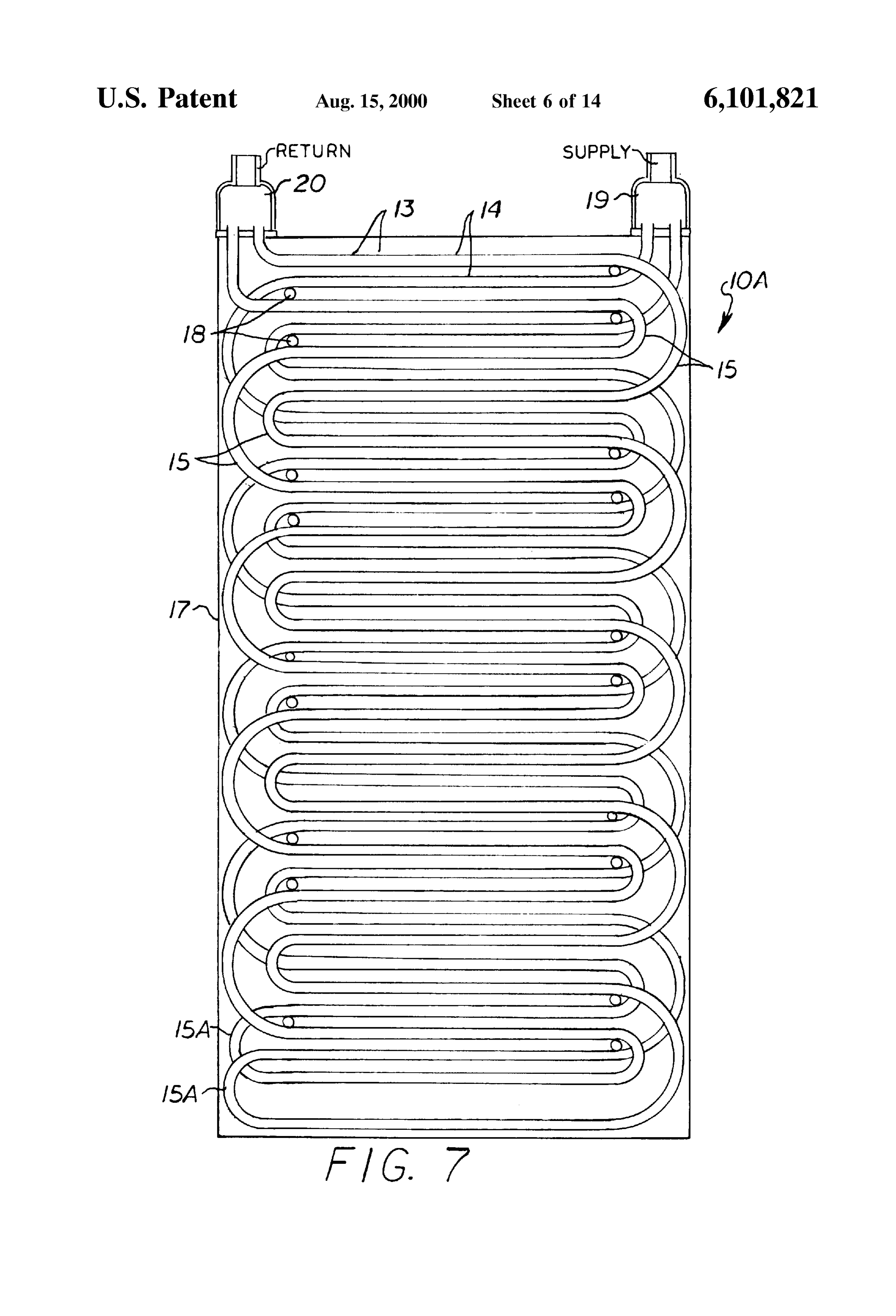
coil (IOC) thermal storage coil system and method which 40 FIG. 7 is a schematic side elevation of a typical “double eliminates the problem of tight working Spaces in deep-tank Serpentine' embodiment of the tall non-Stack ice-coil mod installations required for welding manifold connections and ule and showing a header of two-rows being used for both piping and does not require large access Space for Such an inlet and outlet header, the horizontal tubes may be operations and thereby allows use of a Smaller tank for the Straight, as shown, or sloped.
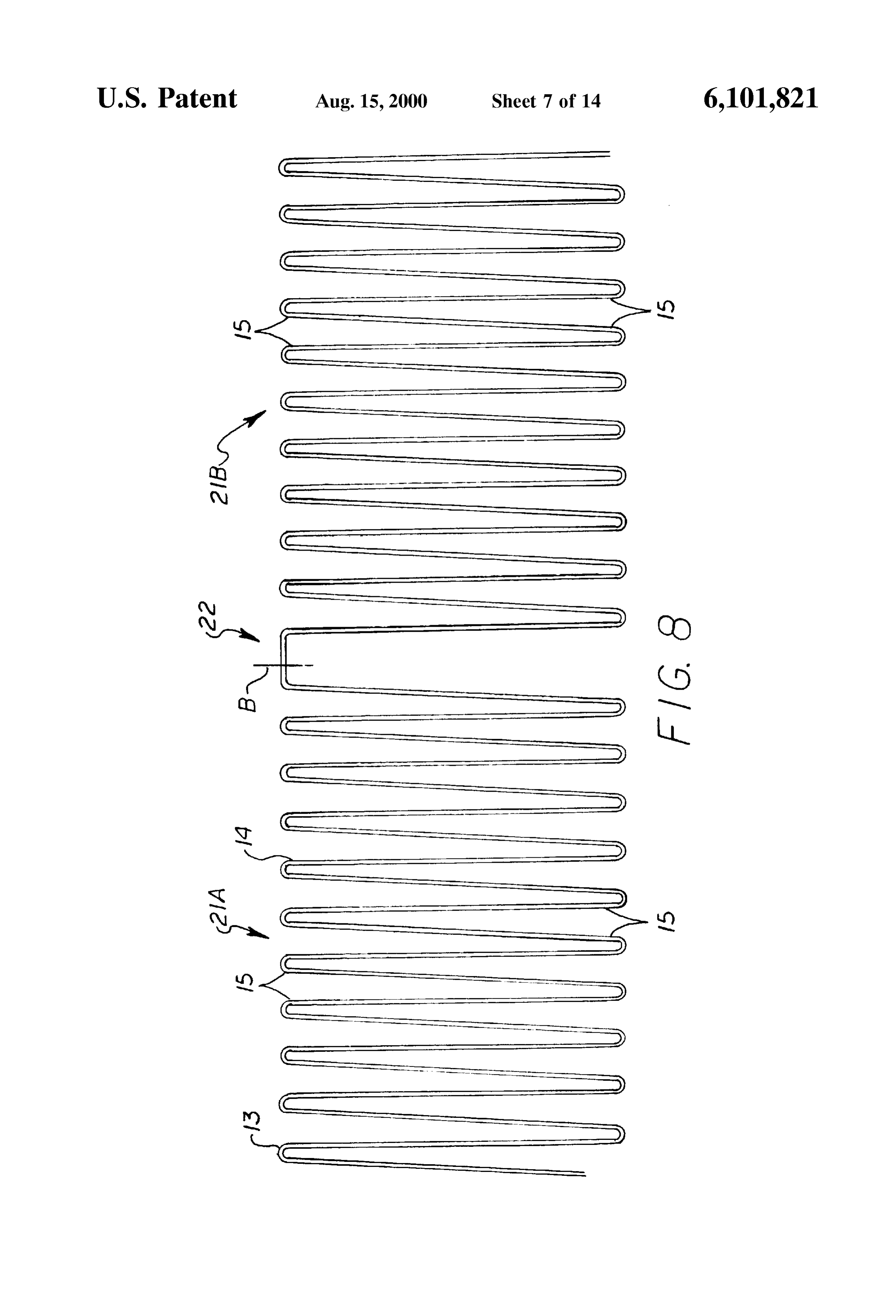
Same total thermal Storage capacity requirement of a con 45 FIG. 8 is a schematic illustration of a tube-bending layout ventional IOC system. pattern to nearly approximate the transition bend and effect A further object of this invention is to provide an ice-on the coil configurations of FIGS. 2 through 5 utilizing a coil (IOC) thermal Storage coil system that provides alter compound 3-dimensional bend to position the adjacent row nate usage of mechanical field piping connections and 50 of Serpentines.
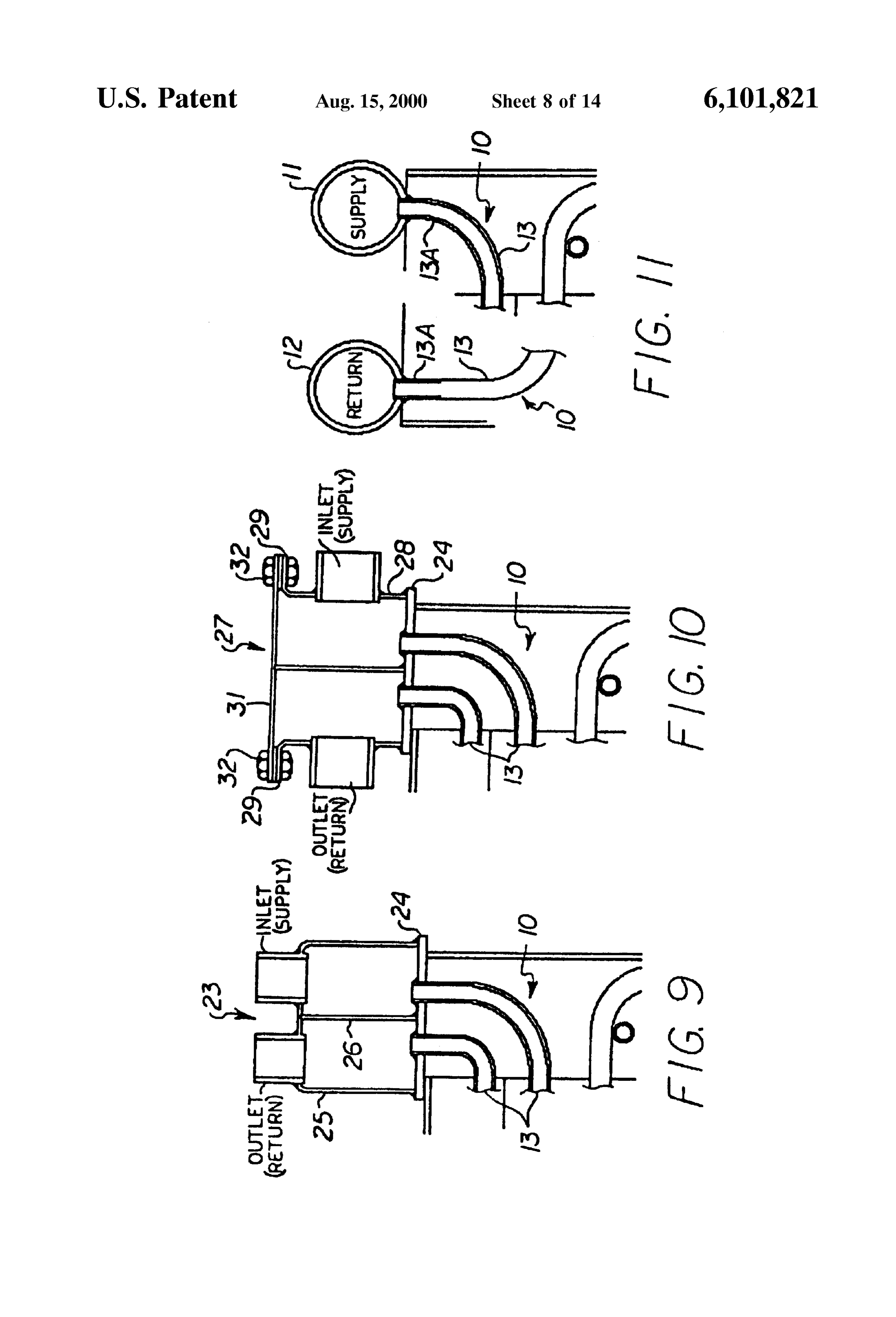
eliminates field welding of manifolds. FIG. 9 is a cross section of a first alternate embodiment of A still further object of this invention is to provide an an inlet and outlet "box' header having a partition arranged ice-on-coil (IOC) thermal storage coil system and method to permit all piping manifolds in the field to be on one side utilizing coils which may be manufactured economically at the top of the coil module.
utilizing modern bending machinery, automated benders, 55 FIG. 10 is a cross section of a second alternate embodi and indexing machines, even though there may be as much ment of a partitioned inlet and outlet “box' header with a as 4 or 5 times as many U-bends compared to conventional removable cover plate for accessing each tube inlet or outlet coil designs. for future Servicing or blocking in the event of a tube leak Other objects of the invention will become apparent from at the lower tube extremities.
time to time throughout the Specification and claims as 60 FIG. 11 is a cross section of a third alternate embodiment hereinafter related. of an inlet and outlet header with up-bends below the header The above noted objects and other objects of the invention to permit operation without Submerging the header and are accomplished by an ice-on-coil (IOC) thermal Storage avoid liquid traps.
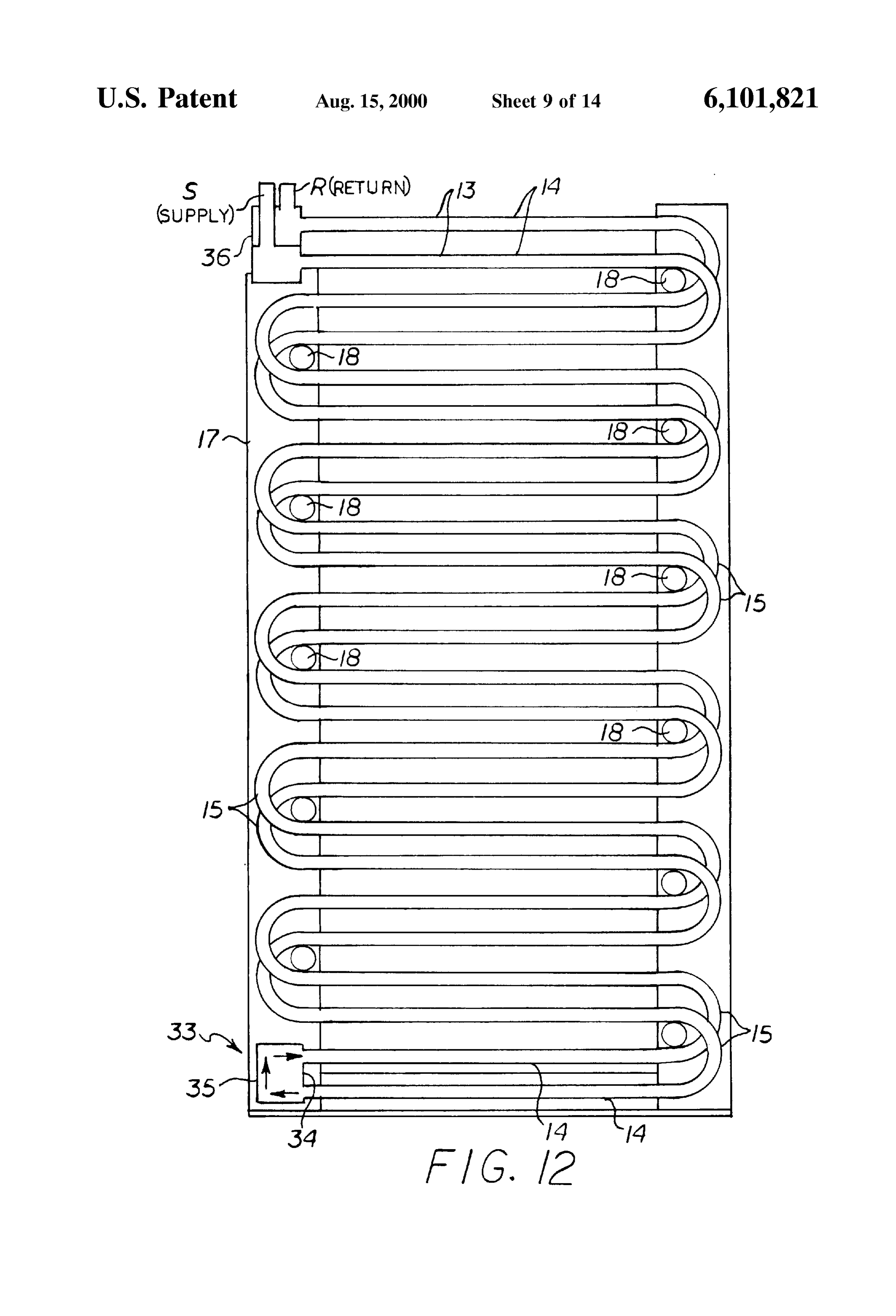
coil System and method utilizing “deep-tank” technology FIG. 12 is a schematic side elevation of a modification of and dimensional relationship of coil height to coil width 65 the tall non-Stack deep-tank ice-coil Serpentine module wherein the coil Serpentine's height (vertical tube having a lower “box' header and an upper “box' header in dimension) is greater than the width (the horizontal accordance with the present invention.
Page 19
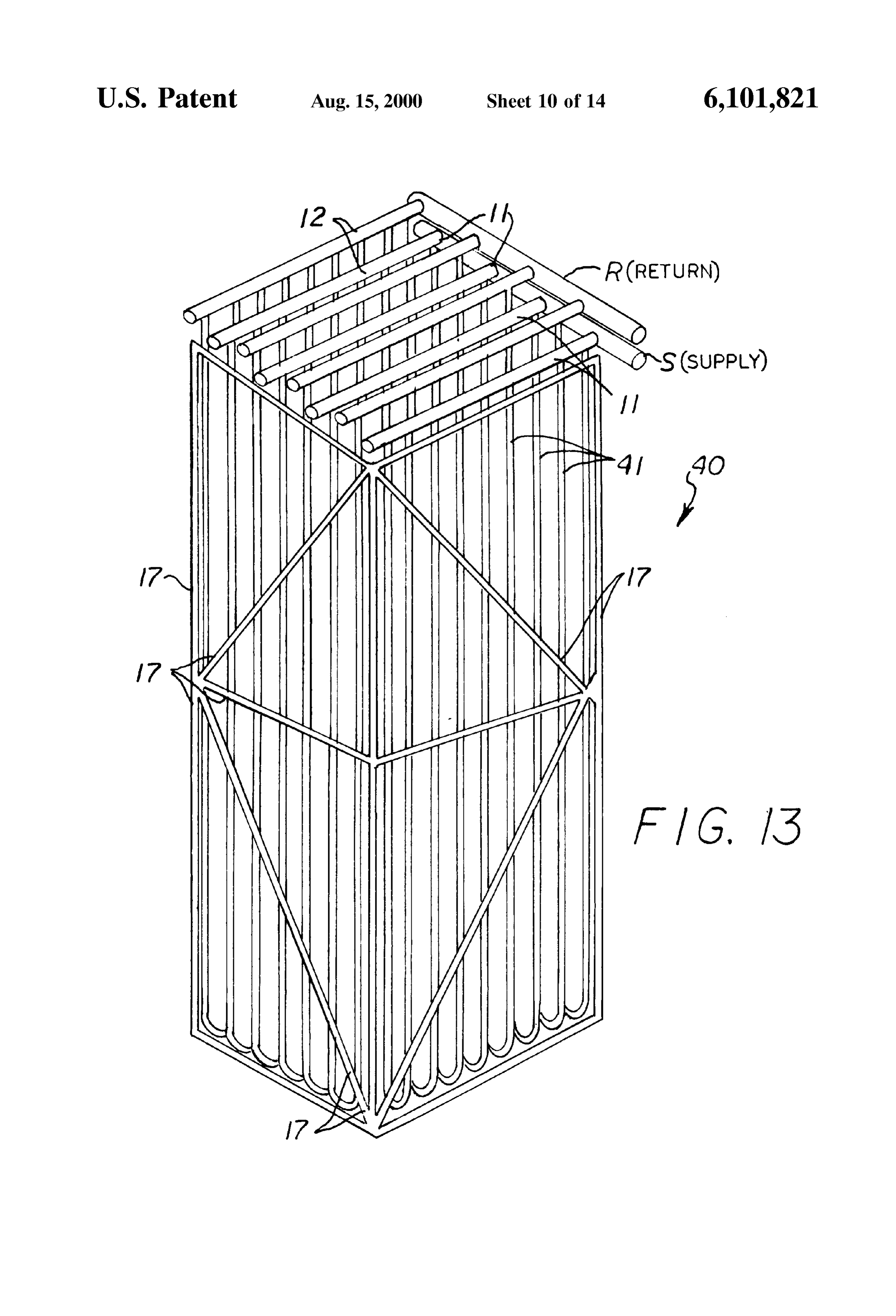
S 6
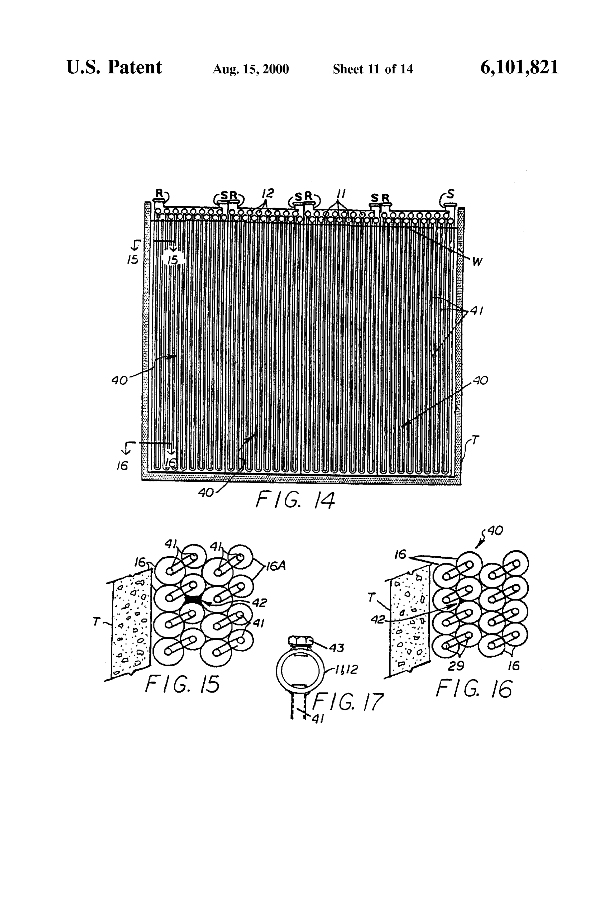
FIG. 13 is a schematic perspective view of a typical very module. Some are even less than 7" high by 21' wide, and in deep non-Stack ice-coil "hairpin' module in accordance with the case of Smaller prior art coil modules, the units are the present invention which utilizes vertical tubes formed typically 4' high by 12' wide. The prior art system typically into individual hairpin configurations between adjacent uses a Stack of two to six deep coil modules. The illustrated rows, clustered into modules and Supported by framing. example shows parallel-piped manifold arrangements of two FIG. 14 is a schematic side elevation of a multi-modular Stacks of coil modules each three modules in height with very-deep hairpin System using the coil System of FIG. 13, each module about 5' wide, 7' in height and 22' in length, but showing the modules in a tank with the headers and mani typical cases can be as many as 5 to 10 modules of height and multiple units in the depth direction for the largest folds above the waterline when the ice has fully melted. district cooling projects.
FIG. 15 is a Schematic transverse croSS Section taken The coils are typically contained in a concrete tank T along line 15-15 of FIG. 14, showing the adjacent ice which is filled with water. AS cold coolant mixtures cylinder and Void space pattern between adjacent tubes at (ethylene glycol/water mixtures) are circulated through the the upper portion of the rows of the hairpin tubes. coils, the water in the tank freezes and forms ice cylinders FIG. 16 is a Schematic transverse croSS Section taken 15 on the coil tubes. There are two choices of operation: (a) along line 16-16 of FIG. 14, showing the adjacent ice either pump the ice water to the load heat exchangers, or (b) cylinder and Void space pattern between adjacent tubes at keep all the water in the tank and pump the coolant in the the lower portion of the rows of the hairpin tubes. coils to the load.
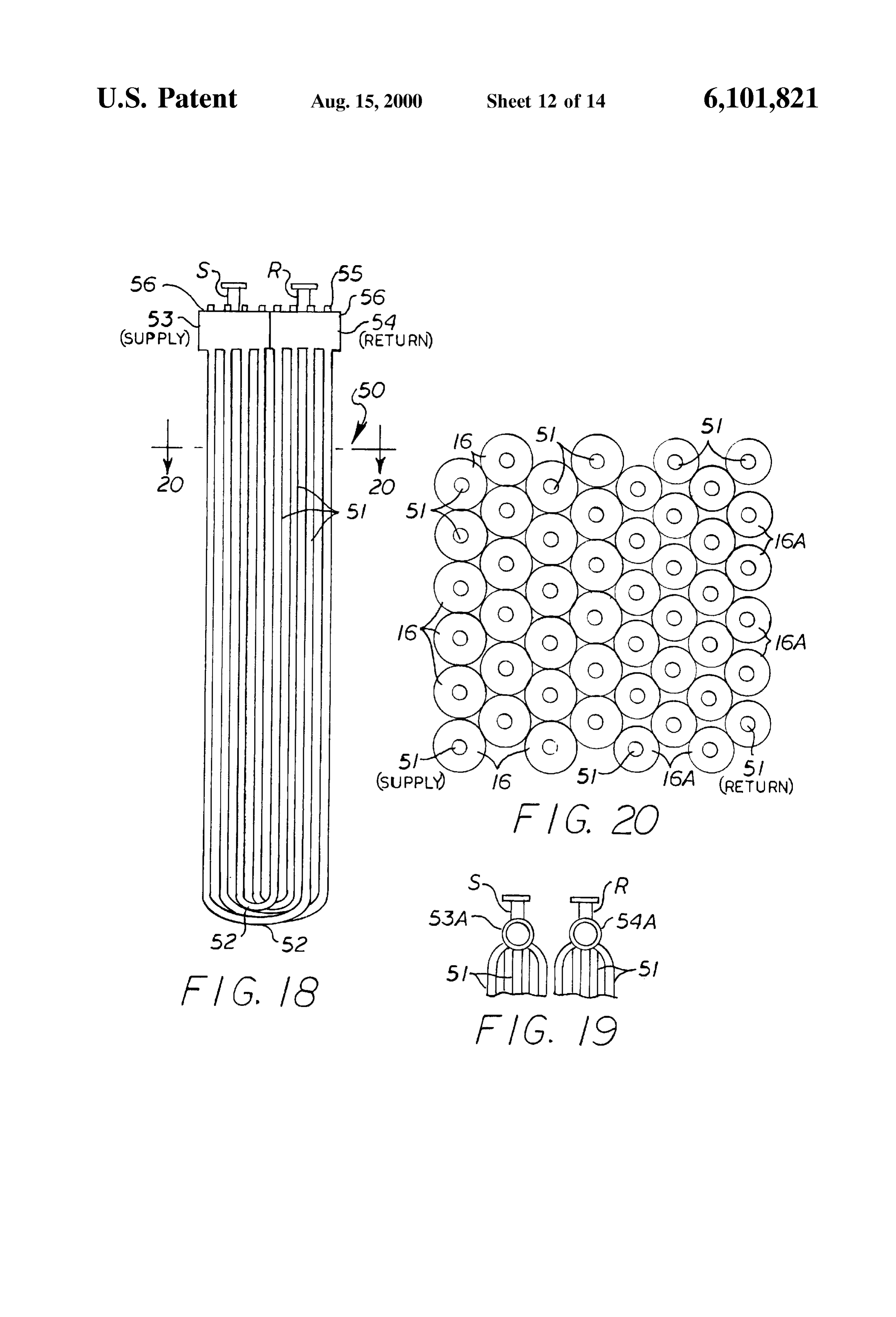
FIG. 17 is a cross section through a tubular coil header of The prior art System requires a clearance Space between the hairpin tube System showing a removable plug that the coils and the side walls of the tankT of Sufficient size to allows access to the inside of the tubes at the inlet and outlet complete the piping installation with Suitable access Space headers for Servicing or inspecting the interior of the coil between the coil modules for welding and Servicing. This tubes. lost piping Space cannot be effectively used for ice-Storage FIG. 18 is a schematic side elevation of a modification of and also requires the tank to be larger than necessary. The the hairpin module which utilizes vertical tubes formed into narrowartSpace 25 prior System also requires field-welded manifolds in the between the coil modules and requires many individual hairpin configurations with nested and laterally wider U-bends and the bottom of the modules and welded joints of both the headers and the manifold piping in removable-plug box headers for tube-end access. the lower depths of the tank in nearly inaccessible places. The stacks of coils must be welded to manifolds before
FIG. 19 is a schematic cross section through the upper end of the hairpin module showing alternate tubular pipe headers being lift or, placed in the tank which requires a very heavy crane alternatively, extra Space must be allotted between with multiple-tube row connections to the headers. coils for welder access during installation. FIG. 20 is a Schematic transverse croSS Section taken along line 20-20 of FIG. 18, showing the adjacent ice welded on-line The steel tubes used for the prior art coils are typically cylinder and Void space pattern between adjacent tubes at 35 from thin strips of as they are manufactured by roll-forming the upper portion of the rows of the U-shaped tubes. sheet steel. These tubes are then formed to about 180 degree U-bends as they make up a Serpentine,
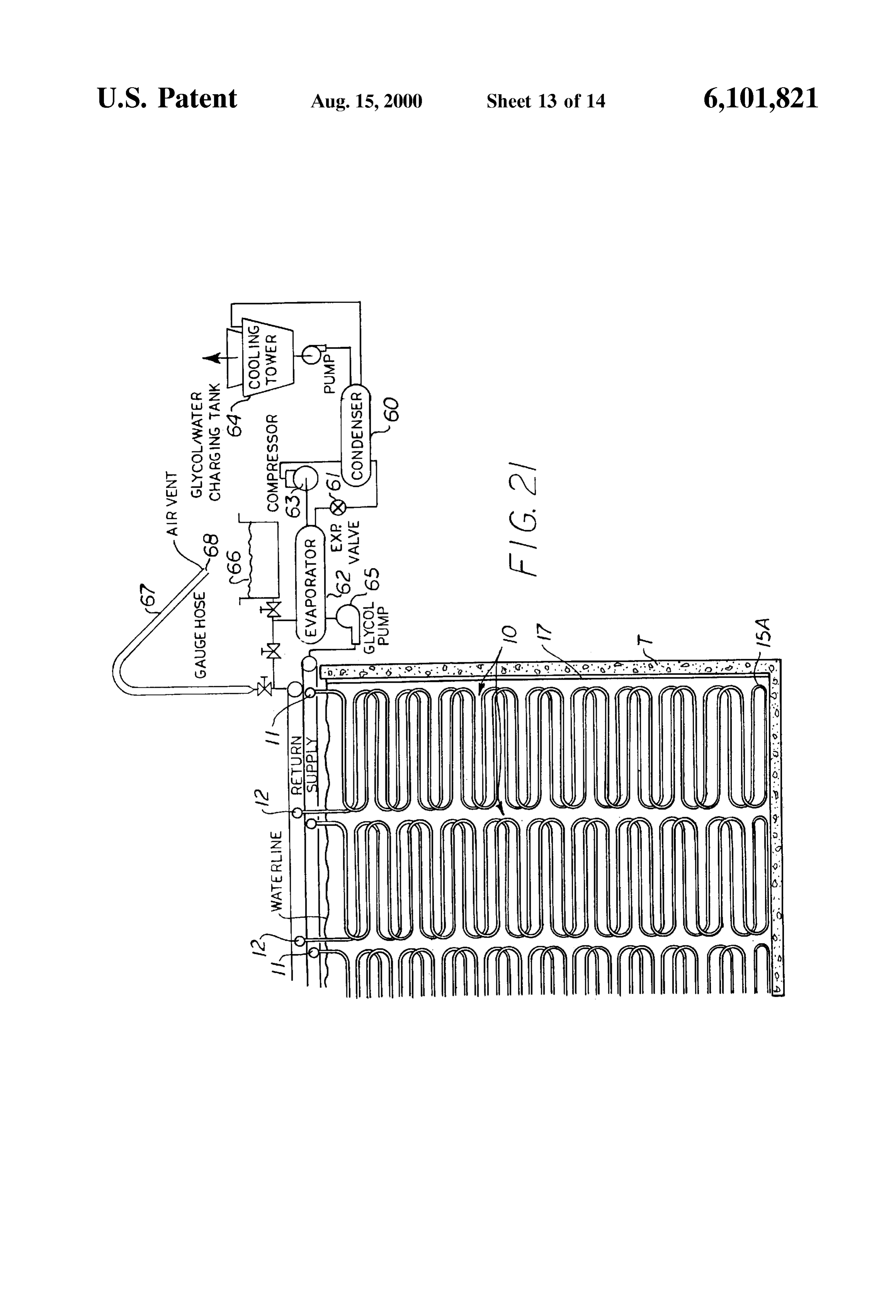
FIG. 21 is a schematic side elevation of a portion of a then the Serpentines are Stacked in a Spaced frame to form a multi-modular tall non-Stack deep-tank ice-coil Serpentine complete coil module and are further welded at the tube ends System illustrating a method of charging a complete System to a drilled or punched header plate. The header plates are with glycol-water while Simultaneously removing air with 40 then enclosed by a welded channel to form a closed manifold out encountering entrapment of air. for the inlet or outlet connections of the coil module. Due to FIG. 22 is a schematic side elevation of a portion of a cramped welding Space, the tubes are more likely to leak at multi-modular tall non-Stack deep-tank ice-coil Serpentine the field-welded connections than any other area, and they System illustrating a piping System that allows the System to are not galvanized for corrosion protection. In the prior art be used for ice melting or ice-building during various 45 System, the manifolds and headers are all underwater, also periods of the day or week to allow minimizing use of occupying useful ice Storage Space.
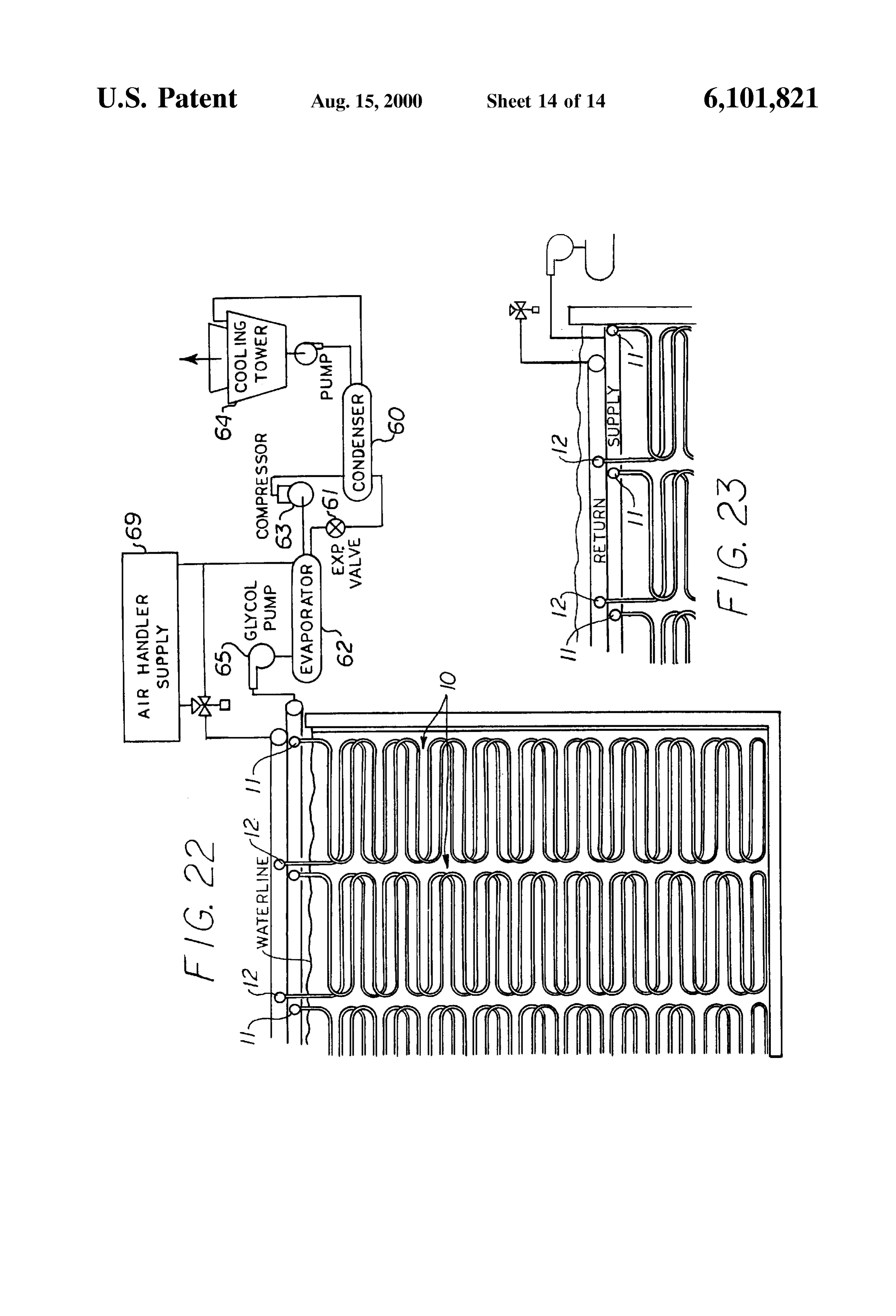
electric power during periods of heavy power demand. The welded joints of the piping and headers are difficult FIG. 23 is a schematic side elevation of a portion of the to acceSS for repair, installation or inspection, should a Systems of FIGS. 21 and 22 showing an alternate arrange glycol leak occur. Glycol leaks will contaminate the entire ment with the Supply and return headerS Submerged below 50 water tank, causing an undesirable depression of the ice the waterline. freeze temperature, leading ultimately to the inability to
DESCRIPTION OF THE PREFERRED
freeze any ice at all and thereby not achieving any significant
EMBODIMENTS
latent heat of fusion of ice Storage.
Referring now to FIGS. 2 through 5, there is shown,
Referring to the drawings by numerals of reference, FIG. 55 Somewhat Schematically, a typical tall non-Stack deep-tank 1 shows, Schematically, an example of a typical deep-tank ice-coil Serpentine module 10 in accordance with the present Stacked module “ice-on-coil (IOC) serpentine arrangement invention, which eliminates the need to Stack multiple coils. of the prior art, having Stacked coils and field-welded It should be noted that the supply headers 11 and return manifolds in the narrow Space between the coil modules and headers 12 are disposed at the top of the module, easily requiring many field-welded joints of both the headers and 60 accessible for final welding of manifolds, or alternate the manifold piping in the lower depths of the tank in nearly mechanical joints of piping, all of which is done above the inaccessible places, and also illustrating the large manifold water line of the ice tank. In FIGS. 2 and 3, the ice tank into piping Space which cannot be effectively used for ice which the coil modules are placed is not shown and the Storage. framing details, which are conventional in the art, are not The prior art Serpentines are at least 2 times as wide as 65 shown.
they are high. In the real applications of these prior art coils, Each coil 10 is formed of tubes 13 bent into a generally the Serpentines are typically up to 7 high by 21' wide per S-shaped Serpentine of Vertically spaced rows of Straight run
Page 20
Sections 14, which may be horizontal or slightly sloped from feature that prevents operational problems in the pumping horizontal, with U-shaped bends 15 at each end of the run. Systems and avoids losing ice building capability adjacent to The inlet ends of the coil tubes 13 are connected to the air pockets.
Supply headers 11 and their outlet ends are connected to the FIG. 4 also shows the typical position of the surface of the return headers 12. A Series of the Serpentines extend down water in the tankT during periods of fully-ice built and fully wardly from the supply header 11 and form the “supply side” melted conditions relative to the position of the headers 11 of the coil and a Second Series of the Serpentines extend and 12 at those periods of time. When the ice is fully melted, upwardly from the lowermost U-shaped bend 15A of the the waterline is below the headers 11 and 12, and when the supply side to the return header 12 to form the “return side” System is fully charged with ice, the waterline is just slightly Second row of the coil. Typically, many of these two-row
Serpentines are placed alongside each other to form a above the headers. Thus, all manifold and header joints are complete module. The “supply side” and “return side” are above, or just below the water Surface of the tank, easily disposed in generally parallel spaced apart vertical planes. accessible for maintenance or assembly, and only the tubes As shown in FIG. 3, the lowermost U-bend in the transition are Submerged for ice-building purposes. In fact, even when from the down-Serpentines and the up-Serpentines is a 15 the coil headers are just below the water Surface during the compound U-bend 15A which is formed into the serpentine time that the ice is fully built on the coil tubes, they will be pair in order to return all glycol from a down-Serpentine above the surface of the water when the ice is fully thawed through an up-Serpentine to the outlet header. The compound (due easily to the lesser density of ice in comparison to water), and visible for leak-checking or leak repair, So that it
U-bend 15A curves about a horizontal axis while sloping at becomes unnecessary to drain the tank to Search for and an angle with respect to a vertical axis. The compound bend may be accomplished by bending the tube, as shown, or a repair leaks, as is required with the current State of the art of welded U-turn fitting. Steel tubed ice-on-coil thermal Storage Systems. It should understood that the straight run sections 14 of As shown in FIG. 5, the coil bundle or module 10 may be the coil tube Serpentines may be horizontal as illustrated in sized from about 22 up to about 30' in height to serve a very FIGS. 2 and 3 or, as illustrated in FIGS. 4 and 5, all straight 25 deep ice tank, with all header connections near or above the runs of the Serpentines may slope upward from the lower water Surface. If galvanized tubes are used, the length of the portion of the U-bends 15 at the lateral sides of the coils in galvanizing tank will determine the maximum height of the a sloped or “near-horizontal” configuration. coil module (typically a 22" nominal module height). Alter As shown schematically in FIGS. 3 and 5, as cold coolant nate non-hot-dip galvanized materials or coatings may allow mixtures (ethylene glycol/water mixtures) are circulated coils of greater height to be produced. FIG. 6 shows a typical through the coils, the water in the tank freezes and forms ice tall non-Stack deep-tank ice-coil Serpentine module 10 Sup ported by framing 17 and the shape of the module as it is to cylinders 16 on the coil tubes 13. As shown in FIG. 3, with be inserted into the deep tank (in the vertical position the present coil configuration, the diameter of the ice cyl inders 16 which form on the down-Serpentines (Supply side) bed shown). The modules 10 may also be transported on a flat vary slightly from a larger diameter at the upper portion to 35 truck in a horizontal Stacked position. A typical coil module a Smaller diameter at the lower portion, and further reduce per 25' truck can be shipped on its Side, with up to four modules in diameter 16A on the up-Serpentines (return side). The bed, or up to eight modules perspecial 50' truck bed.
adjacent ice cylinders 16 are nested in a pattern of “least
In a preferred embodiment, using 1.05" O.D. tubes, the void space', whether the pattern is at the top or bottom (or U-bends anywhere in between) of the coil. “Least void space” is 40 are about 3.5" diameter to allow an ice thickness of defined as the Volumetric area into which ice does not form, about 1.4". Tube circuit lengths up to about 1000' are but is retained as water. As shown in FIG. 5, while near practical for fluid flow and heat transfer at from about 2.5 perfect nesting of the ice cylinderS may occur at the Vertical ft/sec to about 4.5 ft/sec tube velocity. Larger diameter tubes centerline of the coil, more Void space will occur in areas may be used for larger circuits to minimize pressure drop at near the sides due to the tube slope. 45 other spacings.
It should be noted that “least void space” is the most The coil modules of the present invention may be sized desirable ice cylinder pattern that will occur at Very energy for much larger Volumetric usage than current and prior art efficient refrigeration evaporator temperatures, where the units, which are historically about 5' wide, 7 high, and 20 coldest glycol temperature may be a low as about 22 degrees long for a total volume of about 700 cubic feet. The coil F. System designers may choose to use colder evaporator 50 modules of the present invention can be galvanized in most temperatures which can ultimately freeze ice into most of commercial galvanizing tanks when only about 5' wide, 25' the “void spaces', nearly freezing the tank Solid, in order to high, and 6' long, for a total volume of about 750 cubic feet. achieve a greater amount of ice in the Storage tank, but if this The coil modules of the present invention may also be is done, the compressor horsepower requirements will rise enlarged to about 7' long to achieve a volume of about 875 very Substantially. 55 cubic feet, and in Some areas Smaller width modules can be FIG. 4 shows the top and bottom portions of the tall galvanized at longer lengths.
non-Stack deep-tank ice-coil Serpentine module 10 in greater Since all manifolds and interconnecting piping are above detail. The framing 17 and tubular supports 18 near the end the ice tank waterline, the modules can be installed more of each coil are conventional in the art. FIG. 4 shows a closely together to obtain a much more efficient use of Space preferred embodiment of a tubular header and “sloped-tube” 60 in the total System, or to minimize required plan area. coil module construction. In a typical module having a width FIG. 7 is a schematic side elevation of a typical embodi of from about 4' to about 5", the slope, relative to horizontal, ment of a "double-Serpentine' non-Stack ice-coil module is about 72" per pass (pass being defined as the Straight run 10A which may be used alternatively to the embodiments of portion of each tube). AS indicated by arrows, this sloped or FIGS. 2-6. The “double-serpentine” module 10A having “near horizontal” coil configuration greatly facilitates air 65 two-row headers 19 and 20, each used for both an inlet and being pushed out ahead of the glycol/water being filled from outlet header, and each feeding two nested down-Serpentines the inlet header 11, without trapping air. This is a significant and returning two nested up-Serpentines to achieve the same
Page 21
coil height as the previously described embodiments, but of the Supply and return coils are commonly joined by a doing So with the use of coil tubes of only half as long. lower box header 33. The lower box header 33 has a Multiples of these two rows are connected in parallel to form longitudinal side plate 34 with a lower row of longitudinally the module. As with the previous embodiments, the coil Spaced holes through which the open ends of the lowermost serpentines have straight run sections 14 with U-bends 15 at Straight run 14 of the Supply coil tubes are Secured and an each end and the Straight run Sections may be horizontal or upper row of longitudinally Spaced holes through which the Slightly sloped. open ends of lowermost Straight run of the return coil tubes are Secured. A longitudinal, generally U-shaped cover 35
FIG. 8 is a schematic illustration of a tube bending layout enclosed pattern to effect the sloped or near-horizontal coil configu lower header at each end is secured over the side plate 34. The rations described above, but providing an option to the bottom row of33supply allows all liquid and vapor coming from the tubes to reverse flow to the second row compound U-bend 15A of FIG. 7, which will correctly of tubes from the bottom position the adjacent row of Serpentine and produce a arrows, any air entrained(return in the tubes). As indicated by the down-coming Supply tube downward U-bend at an offset position to effect correct liquid streams will enter the lower box header 33 and be two-row Serpentine positioning. The pipe or tubing is bent to pushed upward into the return tubes and thence upward and
form two approximately 20' sections 21A and 21B of sloped outward of the coil assembly. A partitioned Serpentines Separated by a wider Straight mid Section 22. To is shown at the top of the coil module whichupper header 36 form adjacent rows of Serpentines, the tubular configuration inlet flow from the outlet flow. However, it should the Segregates
is bent about the point indicated by the dashed line B and the understood that the lower header 33 may be used with any second 20' serpentine section 21B is folded back on the first of the previously described Supply and return headers. It section 21A. This produces a downward U-bend at the should also be understood that the lower header 33 may be lowest point of the folded 40' serpentine. In the illustrated used with coils having a horizontal Straight run Section or a example, a nominal 630' tube is formed to make 5" straight near-horizontal Sloped Straight run Section. run Sections 14 angularly Sloped to each U-bend 15. ASSum Referring now to FIGS. 13 through 17, there is shown a ing a tube height spacing of about 4" at the centerline, there deep non-Stack ice-on-coil "hairpin' module 40 in accor are 3 tubes per foot of height. (Thus, 5'x3 per foot of 25 heightx21' coil Serpentine heightx2 Serpentines =630"). dance tubes with the present invention which utilizes only vertical 41 formed into adjacent individual elongate U-shaped
Optionally, a welded U-bend may be used to reduce the hairpin configurations, clustered into modules and Supported complexity of forming the compound bends.
FIG. 9 shows, in cross section, an alternate embodiment by framing 17 and held in place by Spacer elements (not shown) This embodiment may use tubes 41 formed of of an inlet and outlet “box' header 23 that allows all piping galvanized Steel, SeamleSS tubing, or metallic alternatives to manifolds in the field to be on one side at the top of the coil galvanized Steel, for example, aluminum, copper, or plastic module. The “box' header has a longitudinal bottom plate 24 with holes therethrough through which the upper ends of tubing.
plate
Extruded aluminum may also be used and rolled into headers or header tubes and provided with plugs or the tubes 13 are Secured. An inverted generally U-shaped 35 removable covers for access. This embodiment can Serve in longitudinal cover 25 enclosed at each end is Secured over ice tankST up to 40' deep with no coil Stacking. AS best Seen the bottom plate 24. A vertical partition plate 26 inside the in FIG. 14, in this embodiment, the supply headers 11 and cover 25 divides the upper ends of the Supply coils from the return headers 12 are also disposed at the upper ends of the upper ends of the return coils and Segregates the inlet flow vertical tubes 41 and there are no header or pipe welds below from the outlet flow. The supply manifold is connected in 40 the waterline W. The headers and manifolds may be sub fluid communication to one side of the cover 25 and the merged as the freezing process proceeds, and fully exposed return manifold is connected in fluid communication to the other Side. as the ice is fully melted.
As shown in FIGS. 15 and 16, with the “hairpin” coil
FIG. 10 shows, in croSS Section, a Second alternate configuration 40, the diameter of the ice cylinders 16 which embodiment of a partitioned inlet and outlet “box' header 27 45 form on the down-leg of the coil (Supply Side) vary slightly having a center partition plate 26. In this embodiment, a from a larger diameter at the upper portion to a Smaller longitudinal box-like cover 28 enclosed at each end is diameter at the lower portion, and further reduce in diameter secured to the bottom plate 24. A vertical partition plate 26 16A on the up-leg of the coil (return side). The adjacent ice inside the cover 25 divides the upper ends of the Supply coils cylinders 16 are nested in a pattern of least Void Space 42 from the upper ends of the return coils and Segregates the 50 (defined as the Volumetric area into which ice does not form, inlet flow from the outlet flow. The cover 28 has an open top but is retained as water), whether the pattern is at the top or end with a pair of longitudinal laterally opposed flanges 29. bottom (or anywhere in between) of the coil. As shown in A removable cover plate 31 is removably mounted over the FIG. 16, near perfect nesting of the ice cylinders 16 occurs open top end by bolts 30. The cover plate 31 can be removed at the lower portion of the coil. FIG. 17 shows, in cross for the purpose of accessing each tube inlet or outlet or for 55 section, a tubular coil header 11, 12 of the hairpin tube Servicing or blocking the tubes in the event of a tube leak at System having a removable plug 43 installed through the the lower tube extremities. upper facing Side of its Side wall that allows access to the FIG. 11 shows, in cross section, a modification of the inside of the tubes 41 at the inlet and outlet headers for tubular inlet header 11 and outlet header 12, wherein the Servicing or inspecting the interior of the coil tubes. upper ends of the tubes 13 are provided with up-bends 13A 60 Referring now to FIG. 18, there is shown, schematically, below the headers to permit operation without Submerging a modification of the very deep non-Stack ice-coil hairpin the header, or to avoid local traps of half-tubes, as may occur module 50 which also utilizes only vertical tubes 51 of on the tubular headers shown in FIG. 4. However, it should SeamleSS tubing or metallic alternatives to galvanized Steel be understood that the use of tubes having Such traps is not that are formed into individual hairpin configurations with considered to be a significant problem. 65 nested and laterally wider U-bends 52 at the bottom and a FIG. 12 illustrates a modification of the serpentine coil supply header 53 and return header 54 at the upper end of the configuration wherein the lowermost Straight run Sections 14 tubes. This embodiment also has no header or pipe welds
Page 22
below the waterline and can serve ice tanks up to about 40' charging the glycol-water from a glycol-water charging tank in height with no coil Stacking. Abox type Supply header 53 66 into the system while removing air from the return and return header 54 with removable plugs 55 is shown in manifold via a gauge hose 67 with an air vent 68. As shown FIG. 18. Supply pipes S and return pipes R may be located in FIG. 22, once the unit is fully charged, the glycol piping on the side or end of the box headers 53 and 54 to permit is circuited through air handler coils 69 for normal operation access to tubes via removable header cover plates 56. FIG. of the total System.
19 shows an alternate tubular supply header 53A and return While this invention has been described fully and com header 54A with multiple-tube row connections to the pletely with Special emphasis upon preferred embodiments, headers which may be used in the system of FIG. 18. it should be understood that, within the scope of the As shown in FIG. 20, the diameter of the ice cylinders 16 appended claims, the invention may be practiced otherwise which form on the down-leg (Supply side) of the coil on one than as Specifically described herein. side (left-hand side as seen in FIG. 20) of the module vary I claim:
Slightly from a larger diameter at the upper portion to a 1. A thermal Storage coil apparatus for installation in an Smaller diameter at the lower portion, and further reduce in ice-on-coil thermal Storage tank for transporting a refriger diameter 16A on the up-leg (return side) of the coil (right 15 ant through Said tank and on which ice cylinders are formed hand Side). The adjacent ice cylinders 16 are nested in a from water in the tank, comprising:
pattern of least void space, whether the pattern is at the top a Serpentine tubular coil having an inlet end, an outlet end, or bottom (or anywhere in between) of the coil. Near perfect and Vertically spaced rows of elongate Straight run nesting of the ice cylinders occurs at the lower portion of the Sections adjoined by U-shaped curved portions at each coil. end of each of Said Straight run Sections, Said coil In the embodiment of FIG. 18, the U-bends 52 at the having a height in a vertical direction greater than its bottom may range from about 6.91" diameter for the shortest width and length in a horizontal direction; and bend to about 22.39" for the longest bend, based on an a Supply header connected with Said inlet end for provid average ice thickness of 1.4", with up to 0.2" thicker ice at 25 ing refrigerant to Said coil and a return header con the inlet, and up to 0.2" thinner ice at the outlet of the tube nected at Said outlet end for withdrawing refrigerant circuit. This embodiment may range in height from about 24 from Said coil, wherein Said coil height in a vertical for a galvanizing tank limitation to about 40' for a truck bed direction is at least twice its width in a horizontal Shipping limitation. The modules may be Stacked to a height direction and Said Supply header and Said return header of about 8" or about 12' wide for shipping. are disposed at an upper end of Said coil. FIG. 21 is a schematic side elevation of a portion of a 2. The thermal Storage coil according to claim 1, wherein multi-modular tall non-Stack deep-tank ice-coil Serpentine Said coil is formed of a Single length of tubing bent to system utilizing the coil configurations of FIGS. 2-6 illus form said elongate Straight run Sections and U-shaped trating a method of charging a complete System with glycol curved portions.
water while Simultaneously removing air without encoun 35 3. The thermal Storage coil according to claim 1, wherein tering entrapment of air. Said coil elongate Straight run Sections between Said FIG. 22 is a schematic side elevation of a portion of a U-shaped portions are disposed at an angle relative to multi-modular tall non-Stack deep-tank ice-coil Serpentine a horizontal axis Sufficient to facilitate removal of air system utilizing the coil configurations of FIGS. 2-6 illus therefrom during filling Said coil with the refrigerant. trating a complete piping System which allows (by Valving 40 4. A thermal Storage coil apparatus for installation in an options, usually automatically controlled by Sensors and ice-on-coil thermal Storage tank for transporting a refriger motors) the System to be used as ice melting or ice-building ant through Said tank and on which ice cylinders are formed during various periods of the day or week to allow mini from water in the tank, comprising:
mizing use of electric power during periods of heavy power demand (typically melting ice in the afternoon periods), and 45 a Serpentine and tubular coil having an inlet end, an outlet end,
Vertically spaced rows of elongate Straight run building ice in the remaining time period. Sections adjoined by U-shaped curved portions at each In FIGS. 21 and 22, a refrigerant, such as “refrigerant 22' end of each of Said Straight run Sections, Said coil (monochlorodifluoromethane), commonly used throughout having a height in a vertical direction greater than its the industry and considered an HCFC type refrigerant, is piped as follows. The liquid refrigerant is condensed in a 50 a Supply and width length in a horizontal direction;
header connected with Said inlet end for provid condenser 60, passes to an expansion valve 61 where it is ing refrigerant to Said coil and a return header con expanded, lowering the pressure and vaporizing the refrig erant in an evaporator 62 where it absorbs heat energy from nected at Said outlet end for withdrawing refrigerant the warmed ethylene-glycol Solution by heat transfer from Said coil, through the tubular heat eXchanger walls within the 55 wherein Said coil has a Supply Section formed of a first evaporator, and becomes fully vaporized. The vaporized plurality of rows of Said elongate Straight run Sections refrigerant (gas) now passes to a compressor 63 where the and U-shaped curved portions extending downwardly gas is pressurized to high pressure and flows to the con from said inlet end with a U-shaped bend at a lower denser 60 where the gas is condensed back to a liquid by heat most end thereof, and transfer through the tubular heat eXchanger walls within the 60 a return Section extending upwardly from Said U-shaped condenser, with the heat passing to a water circuit (within bend formed of a second plurality of rows of said the condenser tubes) and pumped to a cooling tower 64 for elongate Straight run Sections and U-shaped curved heat rejection to the atmosphere. portions and terminating at Said outlet end; The glycol-water mixture is pumped by pump 65 from the Said Supply Section and Said return Section disposed in evaporator (inside tubes) to the Supply manifolds above the 65 parallel spaced apart vertical planes with Said U-shaped ice tank Tand then through the ice-coils 10 to return to the bend at Said lowermost end extending between Said evaporator. FIG. 21 also shows a piping arrangement for parallel spaced vertical planes.
Page 23
5. The thermal Storage coil according to claim 4, wherein Said Supply Section and Said return Section are com Said rows of elongate Straight run Sections of Said Supply monly joined with Said inner chamber and Said Section and Said return Section are offset and Spaced refrigerant and entrained fluids are conducted down apart a distance to form ice cylinders of predetermined Wardly from Said Supply header through Said coil diameter on adjacent Straight run Sections that are Supply Section into Said inner chamber and are nested in a pattern to maximize ice build and minimize transported upwardly through said coil return Section ice Void areas. and outwardly through Said return header. 6. The thermal Storage coil according to claim 4, wherein 10. A thermal Storage coil apparatus for installation in an Said coil has a pair of Said Supply Sections disposed in a ice-on-coil thermal Storage tank for transporting a refriger first vertical plane and a pair of Said return Sections ant through Said tank and on which ice cylinders are formed disposed in a Second vertical plane parallel to Said first from water in the tank, comprising:
Vertical plane; a tubular coil formed of a plurality of Vertical elongate each of Said Supply Sections having an inlet end connected U-shaped tubular members each having a Straight Sup with Said Supply header and a U-shaped bend at a ply leg with an inlet end at an upper end and a parallel lowermost end; 15 laterally Spaced return leg with an outlet end at an upper each of Said return Sections extending upwardly from a end, each of Said Supply and return legs adjoined by a respective Said U-shaped compound bend and having U-shaped curved portion at a bottom end thereof and an outlet end connected with Said return header; and Said coil having a height in a vertical direction greater each Said U-shaped bend at Said lowermost end extending than its width and length in a horizontal direction; and between Said first and Second parallel spaced vertical a Supply header connected with Said inlet ends for pro planes. viding refrigerant to Said coil and a return header 7. The thermal Storage coil according to claim 4, wherein connected with Said outlet ends for withdrawing refrig Said U-shaped bend at Said lowermost end is a compound erant from Said coil, wherein Said coil height in a U-shaped bend curved about a horizontal axis and a vertical 25 Vertical direction is at least twice its width in a hori XS. Zontal direction and Said Supply header and Said return 8. The thermal Storage coil according to claim 4, wherein header are disposed at an upper end of Said coil. Said Supply Section and Said return Section are both 11. The thermal Storage coil according to claim 10, formed of a Single length of tubing bent to form Said wherein elongate Straight run Sections, Said U-shaped curved Said Supply legs and Said return legs are offset and Spaced portions, and Said U-shaped bend at Said lowermost apart a distance to form ice cylinders of predetermined portion. diameter on adjacent legs that are nested in a pattern to 9. A thermal Storage coil apparatus for installation in an maximize ice build and minimize ice Void areas. ice-on-coil thermal storage tank for transporting a refriger 12. A thermal storage coil apparatus for installation in an ant through said tank and on which ice cylinders are formed 35 ice-on-coil thermal Storage tank for transporting a refriger from water in the tank, comprising: ant through Said tank and on which ice cylinders are formed a Serpentine tubular coil having an inlet end, an outlet end, from water in the tank, comprising:
and Vertically spaced rows of elongate Straight run a tubular coil formed of a plurality of Vertical elongate Sections adjoined by U-shaped curved portions at each U-shaped tubular members each having a Straight Sup end of each of Said Straight run Sections, said coil 40 ply leg with an inlet end at an upper end and a parallel having a height in a vertical direction greater than its laterally Spaced return leg with an outlet end at an upper width and length in a horizontal direction; end, each of Said Supply and return legs adjoined by a a Supply header connected with Said inlet end for provid U-shaped curved portion at a bottom end thereof and ing refrigerant to Said coil and a return header con Said coil having a height in a vertical direction greater nected at Said outlet end for withdrawing refrigerant 45 than its width and length in a horizontal direction; and from Said coil; and a Supply header connected with Said inlet ends for pro an enclosed box-like lower header having an inner cham viding refrigerant to Said coil, and a return header ber; and connected with Said outlet ends for withdrawing refrig Said coil has a Supply Section formed of a first plurality of erant from Said coil, wherein Said plurality of Vertical rows of Said elongate Straight run Sections and 50 elongate U-shaped tubular members comprise an outer U-shaped curved portions extending downwardly from U-shaped tubular member having a Straight Supply leg Said inlet end with a lowermost Straight run Section of with an inlet end at an upper end and a parallel laterally Said Supply Section having an open end in fluid com Spaced Straight return leg with an outlet end at an upper munication with a lower portion of Said lower header end adjoined by a wide U-shaped curved portion at a inner chamber; 55 bottom end thereof; and
Said coil has a return Section formed of a Second plurality a plurality of inner Said vertical elongate U-shaped tubular of rows of Said elongate Straight run Sections and members having Successively Smaller U-shaped curved U-shaped curved portions with a lowermost Straight run portions at a bottom end thereof nested between Said Section of Said return Section having an open end in Supply leg and return leg of Said outer U-shaped tubular fluid communication with an upper portion of Said 60 member with all of Said Supply legs and return legs in lower header inner chamber, Said return Section extend generally parallel laterally Spaced relation. ing upwardly from Said lower header and terminating at 13. The thermal Storage coil according to claim 12, Said outlet end; and wherein
Said Supply Section and Said return Section disposed in Said coil has a plurality of Sets of Said outer U-shaped parallel Spaced apart vertical planes with Said lower 65 tubular member and nested said inner U-shaped tubular header eXtending between Said parallel spaced vertical members disposed in generally parallel spaced vertical planes, wherein planes, and
Page 24
each of Said inlet ends connected with Said Supply header a Supply header connected with Said inlet end for provid and each of Said outlet ends connected with Said return ing refrigerant to Said coil and a return header con header. nected at Said outlet end for withdrawing refrigerant 14. The thermal Storage coil according to claim 13, from Said coil, wherein wherein Said coil has a Supply Section formed of a first plurality Said Straight Supply legs and Said return legs are offset and of rows of Said elongate Straight run Sections and Spaced apart a distance to form ice cylinders of prede U-shaped curved portions extending downwardly termined diameter on adjacent legs that are nested in a from said inlet end with a U-shaped bend at a pattern to maximize ice build and minimize ice void lowermost end thereof, and
15. An ice-on-coil thermal Storage System, comprising: a return Section extending upwardly from Said a generally rectangular ice tank Suitable for containing U-shaped bend formed of a second plurality of rows of Said elongate Straight run Sections and U-shaped water and having a bottom wall and opposed Side walls, curved portions and terminating at Said outlet end; a Serpentine tubular coil having an inlet end, an outlet end, Said Supply Section and Said return Section disposed in and Vertically spaced rows of elongate Straight run 15 parallel Spaced apart vertical planes with Said Sections adjoined by U-shaped curved portions at each U-shaped bend at Said lowermost end extending end of each of Said Straight run Sections disposed in Said between said parallel spaced vertical planes. tank for transporting a refrigerant through Said tank and 21. The ice-on-coil thermal Storage System according to for forming ice cylinders thereon from water in Said tank, Said coil having a height in a vertical direction claim 20, wherein greater than its width and length in a horizontal direc Said rows of elongate Straight run Sections of Said Supply tion; and Section and Said return Section are offset and Spaced a Supply header connected with Said inlet end for provid apart a distance to form ice cylinders of predetermined ing refrigerant to Said coil and a return header con diameter on adjacent Straight run Sections that are nected at Said outlet end for withdrawing refrigerant 25 nested in a pattern to maximize ice build and minimize from Said coil, wherein Said coil height in a vertical ice Void areas.
direction is at least twice its width in a horizontal 22. An ice-on-coil thermal Storage System, comprising: a direction and Said Supply header and Said return header generally rectangular ice tank Suitable for containing water are disposed at an upper end of Said coil. and having a bottom wall and opposed side walls, 16. The ice-on-coil thermal Storage System according to a tubular coil disposed in Said tank for transporting a claim 15, wherein refrigerant through said tank and for forming ice cyl Said coil Straight run Sections and U-shaped curved por inders thereon from water in Said tank, Said coil formed tions are Submerged in water contained in Said tank and of a plurality of Vertical elongate U-shaped tubular Said Supply header and Said return header are disposed members each having a straight supply leg with an inlet above the water Surface. end at an upper end and a parallel laterally Spaced 17. The ice-on-coil thermal Storage System according to 35 return leg with an outlet end at an upper end, each of claim 15, wherein Said Supply and return legs adjoined by a U-shaped Said coil Straight run Sections and U-shaped curved por curved portion at a bottom end thereof and Said coil tions are Submerged in water contained in Said tank and having a height in a vertical direction greater than its Said Supply header and Said return header are just below 40 width and length in a horizontal direction; and the water Surface. a Supply header connected with Said inlet ends for pro 18. The ice-on-coil thermal Storage System according to viding refrigerant to Said coil and a return header claim 15, wherein connected with Said outlet ends for withdrawing refrig Said Supply header and Said return header are disposed at erant from Said coil, wherein Said coil height in a a height relative to Said tank bottom wall So as to be 45 Vertical direction is at least twice its width in a hori Submerged just below the Surface of water in Said tank Zontal direction and Said Supply header and Said return during periods of a fully ice-built condition and to be header are disposed at an upper end of Said coil. exposed above the water Surface during periods of a 23. The ice-on-coil thermal Storage System according to fully ice-melted condition. claim 22, wherein 19. The ice-on-coil thermal Storage System according to 50 Said Supply header and Said return header are dispposed at claim 15, wherein a height relative to Said tank bottom wall So as to be Said coil elongate Straight run Sections between Said Submerged just below the Surface of water in Said tank U-shaped portions are disposed at an angle relative to during periods of a fully ice-built condition and to be a horizontal axis Sufficient to facilitate removal of air exposed above the water Surface during periods of a therefrom during filling Said coil with the refrigerant. 55 fully ice-melted condition.
20. An ice-on-coil thermal Storage System, comprising: 24. The ice-on-coil thermal Storage System according to a generally rectangular ice tank Suitable for containing claim 22, wherein water and having a bottom wall and opposed Side walls, Said Supply legs and Said return legs are offset and Spaced a Serpentine tubular coil having an inlet end, an outlet end, apart a distance to form ice cylinders of predetermined and Vertically spaced rows of elongate Straight run 60 diameter on adjacent legs that are nested in a pattern to Sections adjoined by U-shaped curved portions at each maximize ice build and minimize ice Void areas. end of each of Said Straight run Sections disposed in Said 25. An ice-on-coil thermal Storage System comprising: tank for transporting a refrigerant through Said tank and a generally rectangular ice tank Suitable for containing for forming ice cylinders thereon from water in Said water and having a bottom wall and opposed Side walls, tank Said coil having a height in a vertical direction 65 a tubular coil disposed in Said tank for transporting a greater than its width and length in a horizontal direc refrigerant through said tank and for forming ice cyl tion; and inders thereon from water in Said tank, Said coil formed
Page 25
of a plurality of Vertical elongate U-shaped tubular Supply leg and retrun leg of Said outer U-shaped tubular members each having a Straight Supply leg with an inlet member with all of Said Supply legs and return legs in end at an upper end and a parallel laterally Spaced generally parallel laterally Spaced relation. return log with an outlet end at an upper end, each of 26. The ice-on-coil thermal Storage System according to Said Supply and return legs adjoined by a U-shaped 5 claim 22, wherein curved portion at a bottom end thereof and Said coil Said coil has a plurality of Sets of Said outer U-shaped having a height in a vertical direction greater than its tubular member and nested saidinner U-shaped tubular width and length in a horizontal direction; and members disposed in generally parallel spaced vertical a Supply header connected with Said inlet ends for pro planes, and
Viding refrigerant to Said coil and a return connected each of Said inlet ends connected with Said Supply header with said outlet ends for withdrawing refrigerant from and each of Said outlet ends connected with Said return Said coil, wherein header.
Said plurality of Vertical elongate U-shaped tubular mem 27. An ice-on-coil thermal Storage System according to bers comprise an outer U-shaped tubular member hav 15 claim 26, wherein ing a Straight Supply leg with an inlet end at an upper Said Straight Supply legs and Said return legs are offset and end and a parallel laterally Spaced Straight return leg Spaced apart a distance to form ice cylinders of prede with an outlet end at an upper end adjoined by a wide termined diameter on adjacent legs that are nested in a U-shaped curved portion at a bottom end thereof, and pattern to maximize ice build and minimize ice Void a plurality of inner Said vertical elongate U-shaped tubular CS.
members having Successively Smaller U-shaped curved portions at a bottom end thereof nested between Said
Provenance
- Collection
- Cited prior art
- Original PDF
- patentimages.storage.googleapis.com →
- Filed
- 1999-05-21
- Pages
- 25
- Method
- pdftotext (the PDF's own text layer) + pdftoppm 300dpi page scans
- Source
- Google Patents bibliographic record
- Granted
- 2000-08-15
- Inventors
- Robert E. Cates; Evapco International Inc
- Transcribed from
- patentimages.storage.googleapis.com →