patent · US5598720
Air bubble heat transfer enhancement system coolness storage apparatus
4 February 1997
Page 1 — bibliographic record
United States Patent (19) 11 Patent Number: 5,598,720 MacCracken et al. (45) Date of Patent: Feb. 4, 1997 (54) AIR BUBBLE HEAT TRANSFER (56) References Cited
ENHANCEMENT SYSTEM COOLNESS
STORAGE APPARATUS U.S. PATENT DOCUMENTS 3,998,071 12/1976 Barthel ...................................... 62A430 75) Inventors: Mark M. MacCracken, Englewood, 4,096,709 6/1978 Barthel ............. N.J.; Brian M. Silvetti, Tompkins 4,757,690 7/1988 Hollowczenko et al. .................... 62/59 E. C, NY; Jose R. Bonet, North Primary Examiner-Christopher B. Kilner ergen, N.J. Attorney, Agent, or Firm-Bond, Schoeneck & King, LLP 73) Assignee: Calmac Manufacturing Corporation, (57) ABSTRACT Englewood, N.J.
In coolness storage apparatus wherein brine in heat exchange tubes freezes and melts water and air is bubbledup 21 Appl. No.: 510,204 through the water during the melting cycle to enhance heat 22 Filed: Aug. 2, 1995 exchange efficiency by gently circulating the water, vertical 6 heat transfer strips in thermal conducting contact with the (51) Int. C. .................................................... F2SD 17/02 tubes for accelerating melting along each strip early in the 52 U.S. C. ................................... 62/434; 62/59; 165/10; discharge cycle to open channels through which the air 165/104.17 bubbles stream to the top zone of the tank.
58 Field of Search ............................. 165/10 A, 104.17;
62/434, 430, 59 15 Claims, 3 Drawing Sheets
Page 2
Drawing sheet — no readable text.
Page 3
Drawing sheet — no readable text.
Page 4
Drawing sheet — no readable text.
Page 5
AR BUBBLE HEAT TRANSFER growing volumes of water still enclosed within the melting ENHANCEMENT SYSTEM COOLNESS ice. Not until the continuous horizontal ice layers begin to STORAGE APPARATUS melt and perforate, which occurs substantially simulta neously throughout the tank in a properly designed coun
BACKGROUND OF THE INVENTION terflow system, do the air bubble streams begin circulating the water in the operative regions of the tank affected by the
Certain high performance coolness storage systems spiral heat exchange tubes.
include a covered cylindrical tank with heat exchange tube spirals spaced one over the other and connected to inlet and SUMMARY OF THE INVENTION outlet headers so that a phase-change material (PCM) in the 10 The air bubble heat transfer enhancement system of the tank may be alternately frozen and thawed by brine circu invention is applicable to coolness storage apparatus lating through tubes immersed in the PCM. Such systems wherein heat exchange tubes are arranged in a tank and have been sold commercially for many years by Calmac
Manufacturing Corporation of Englewood, N.J., U.S.A., wherein inlet and outlet headers are connected to the tubes under the trademarks LEVLOAD and ICE BANK and are 5 so that brine flows in the tubes to freeze substantially solid described in U.S. Pat. Nos. 4,671,347, 4,954,278 and 5,054, and melt a mass of PCM around the tubes during cycles of 298. coolness charging and discharging respectively. The system In a preferred form of these coolness storage devices the includes pressurized air supply conduit means in the tank. circulation of the brine through the heat exchange tubes is in 20 means and ismeans
Air bubbler is connected to the air supply conduit located beneath the heat exchange tubes.
a counterflow or opposite direction from one tube spiral to Aperture means are located in the air bubbler means from the next. This is achieved by having a first brine inlet header which bubbles stream upwardly into the liquid PCM during in a central zone of the tank free of the tubes connected the discharge cycle and upon introduction of pressurized air through every other tube spiral to a first outlet header in an into the air bubbler means through the air supply conduit outer tank zone surrounding the bundle of tube spirals, and 25 means. Heat transfer elements extend upwardly from adja a second inlet header alongside the first outlet header in the cent the air bubbler means in thermal conductive contact outer zone connected through the alternate tube spirals to a with the heat exchange tubes for accelerating PCM melting second brine outlet header alongside the first inlet header in early in the discharge cycle to open channels through which the central tank Zone.
the air bubbles can stream upwardly through the melted
In the operation of these high performance coolness 30 PCM.
storage systems the PCM is alternately melted during a The tubes may be arranged in the tank in substantially discharge cycle and frozen during a charging cycle. During planar spirals spaced one over the other. First and second the charging cycle ice builds up around each heat exchange tube spiral starting from the end adjacent the inlet header and and outerinlet pairs of ends and outlet headers may be connected to inner of every spiral so that brine flows in opposite progressing to the end adjacent the outlet header. With the 35 directions in adjacent spirals to progressively freeze and counterflow arrangement of brine circulation in alternate melt the PCM substantially uniformly. heat exchange tube spirals, this results in progressively The aperture means may be a series of spaced holes. totally freezing the PCM at a uniform rate in all regions of the PCM in the tank affected by the tubes. A substantially The heat transfer elements are preferably metal strips, solid block of ice is thereby formed around he tubes. During 40 specifically of aluminum, extending from above each the discharge cycle the ice is melted from around the tubes respective air bubbler hole in thermal conductive contact in the same progressive fashion. with the heat exchange tubes. Preferably the strips project In other differing designs of coolness storage apparatus in may above the surface of the PCM in the tanktop zone. The strips the prior art, heat transfer efficiency is known to be enhanced increased be woven inwardly and outwardly around the tubes for thermal conductive contact therewith. The lower by introducing air bubbles into liquid PCM in the bottom of 45 most end of each strip may be wrapped partially around and the tank so that streams of bubbles rising upwardly gently secured to the air bubbler tube alongside its associated hole. circulate the PCM as it melts. These differing forms of Each air bubbler tube hole may be angled slightly off vertical coolness storage devices typically consist of rectangular to direct its bubble stream against an adjacent face of the tanks in which a Zone of PCM in the bottom of the tank never freezes, and it is there in that always-liquid bottom 50 associated heat transfer strip. zone that the air bubbles originate through perforated tubes Check valve means may be associated with the air supply connected to a source of pressurized air. conduit means to prevent back flow of liquid above the Application of air bubble systems to known spiral tube bottom zone of the tank where it could freeze during the charging cycle. The air supply conduit means may comprise counterflow heat exchangers has notheretofore been notably first and second air supply conduits extending downwardly successful. As a discharge cycle commences and ice begins 55 from the top Zone of the tank from outer and central zones to melt uniformly throughout that zone of the tank affected respectively of the tank. The air bubble tube may be con by the spiral tubes, there is a prolonged period when nected at its inner and outer ends to the first and second air uninterrupted horizontal layers of ice are still present across supply conduits respectively, and the check valve means the tank, including a continuous layer beneath the lowermost tube spiral above the always-liquid bottom Zone where the may comprise individual check valves located in each of the first and second air supply conduits in the bottom Zone tank.
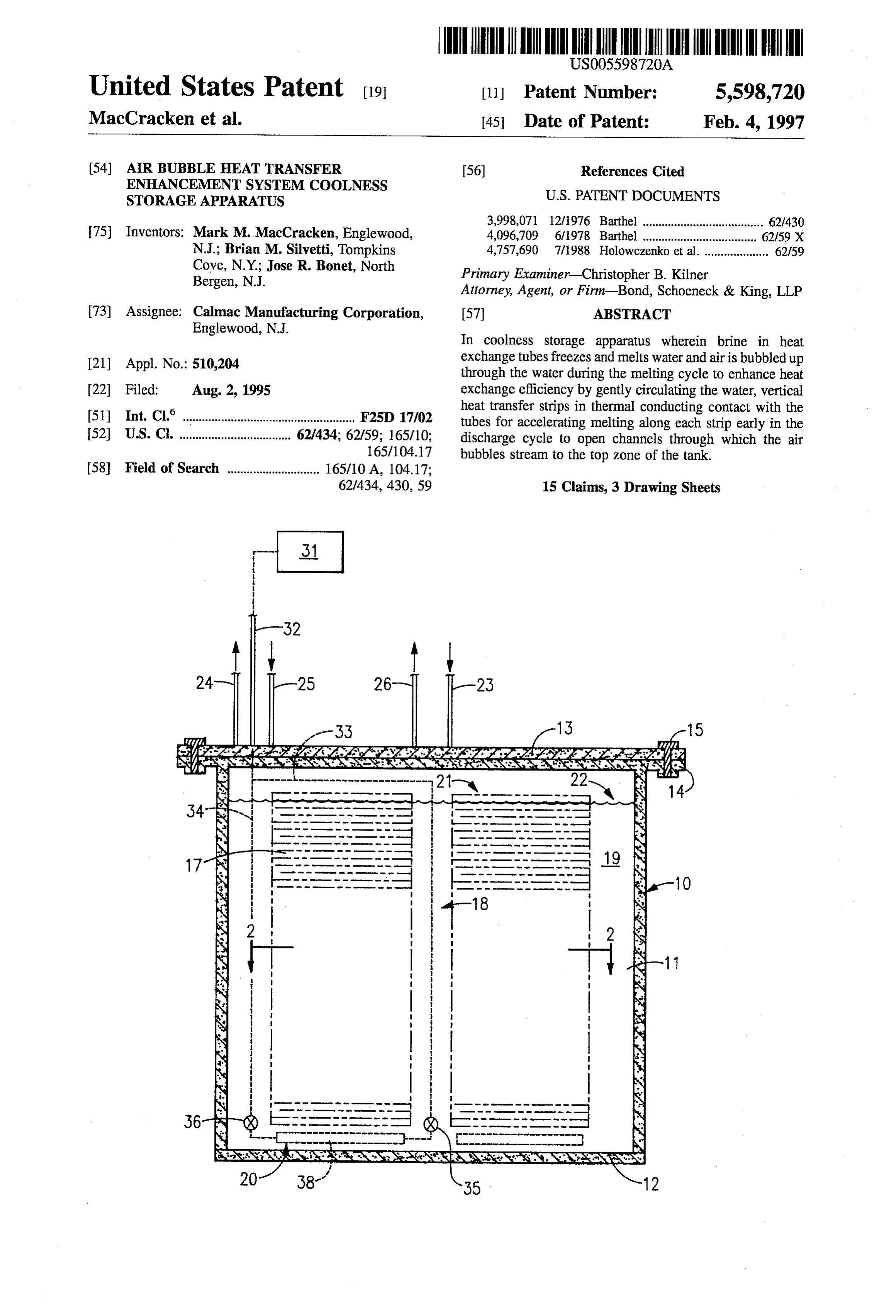
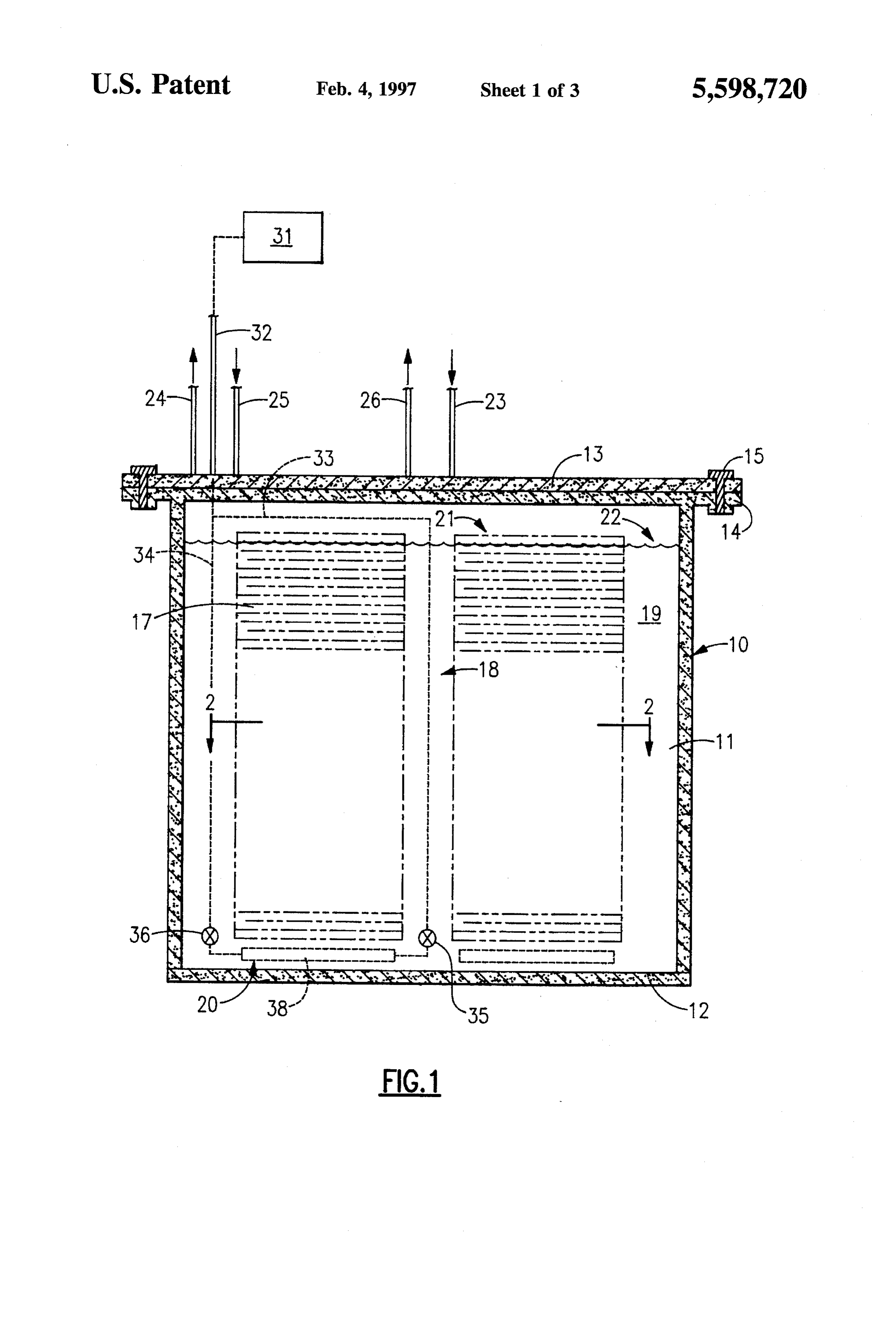
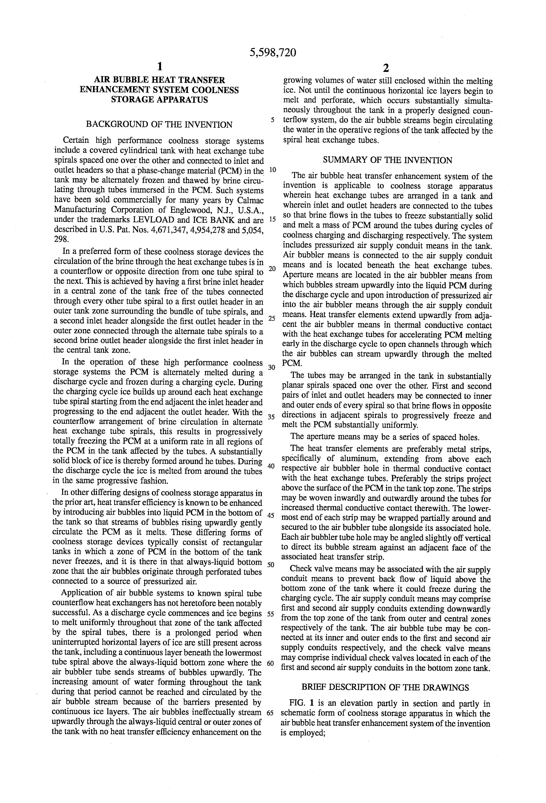
air bubbler tube sends streams of bubbles upwardly. The increasing amount of water forming throughout the tank BRIEF DESCRIPTION OF THE DRAWINGS during that period cannot be reached and circulated by the air bubble stream because of the barriers presented by FIG. 1 is an elevation partly in section and partly in continuous ice layers. The air bubbles ineffectually stream 65 schematic form of coolness storage apparatus in which the upwardly through the always-liquid central or outer zones of air bubbleheat transfer enhancement system of the invention the tank with no heat transfer efficiency enhancement on the is employed;
Page 6
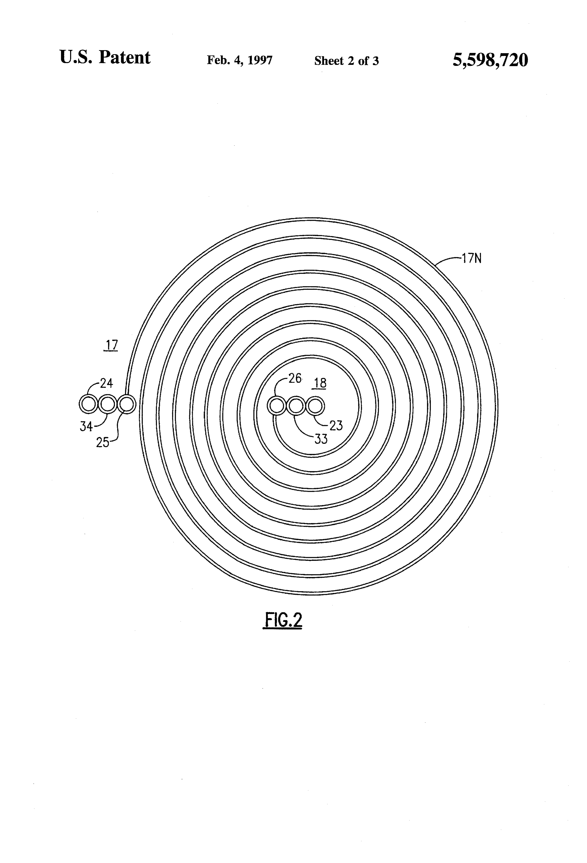
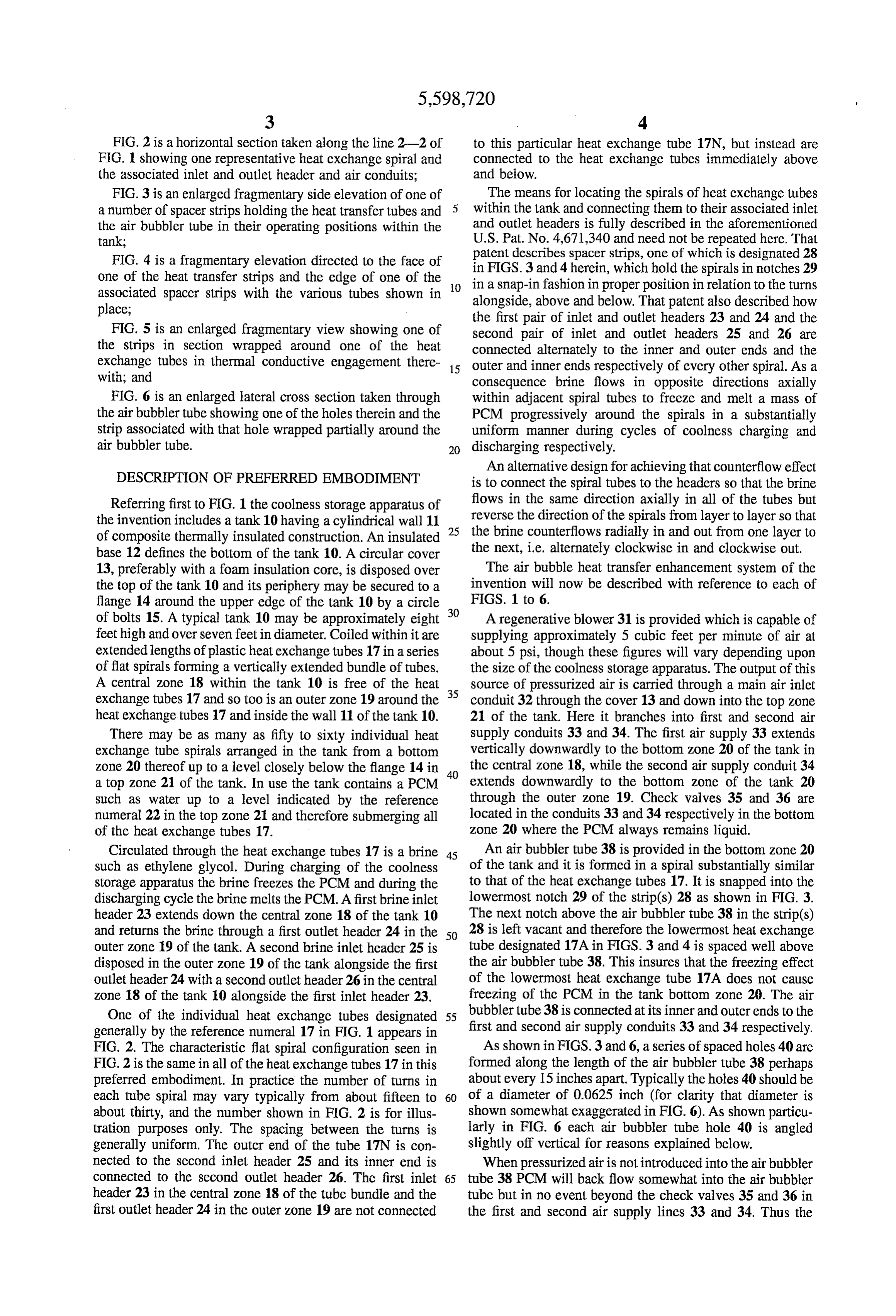
FIG. 2 is a horizontal section taken along the line 2-2 of to this particular heat exchange tube 17N, but instead are FIG. 1 showing one representative heat exchange spiral and connected to the heat exchange tubes immediately above the associated inlet and outlet header and air conduits; and below.
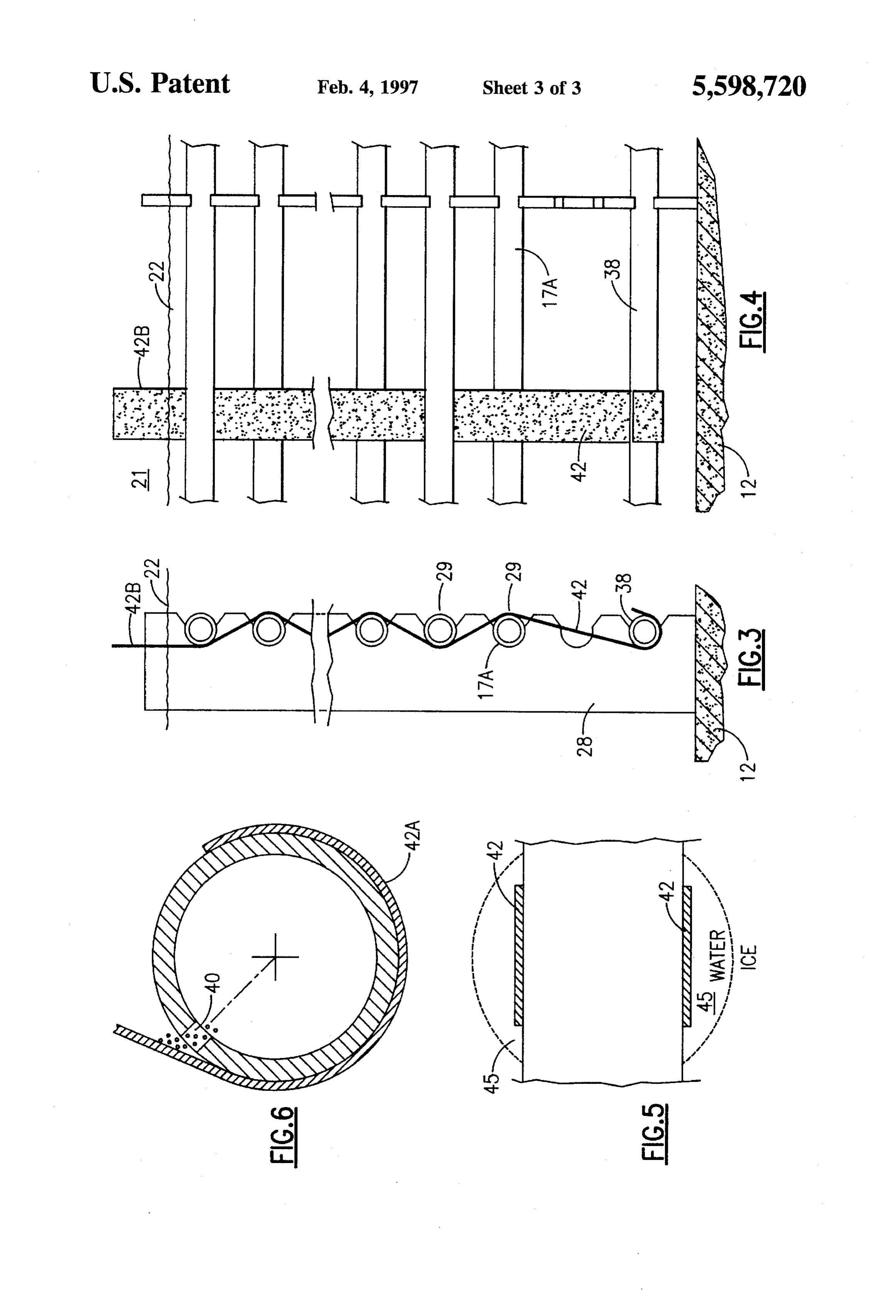
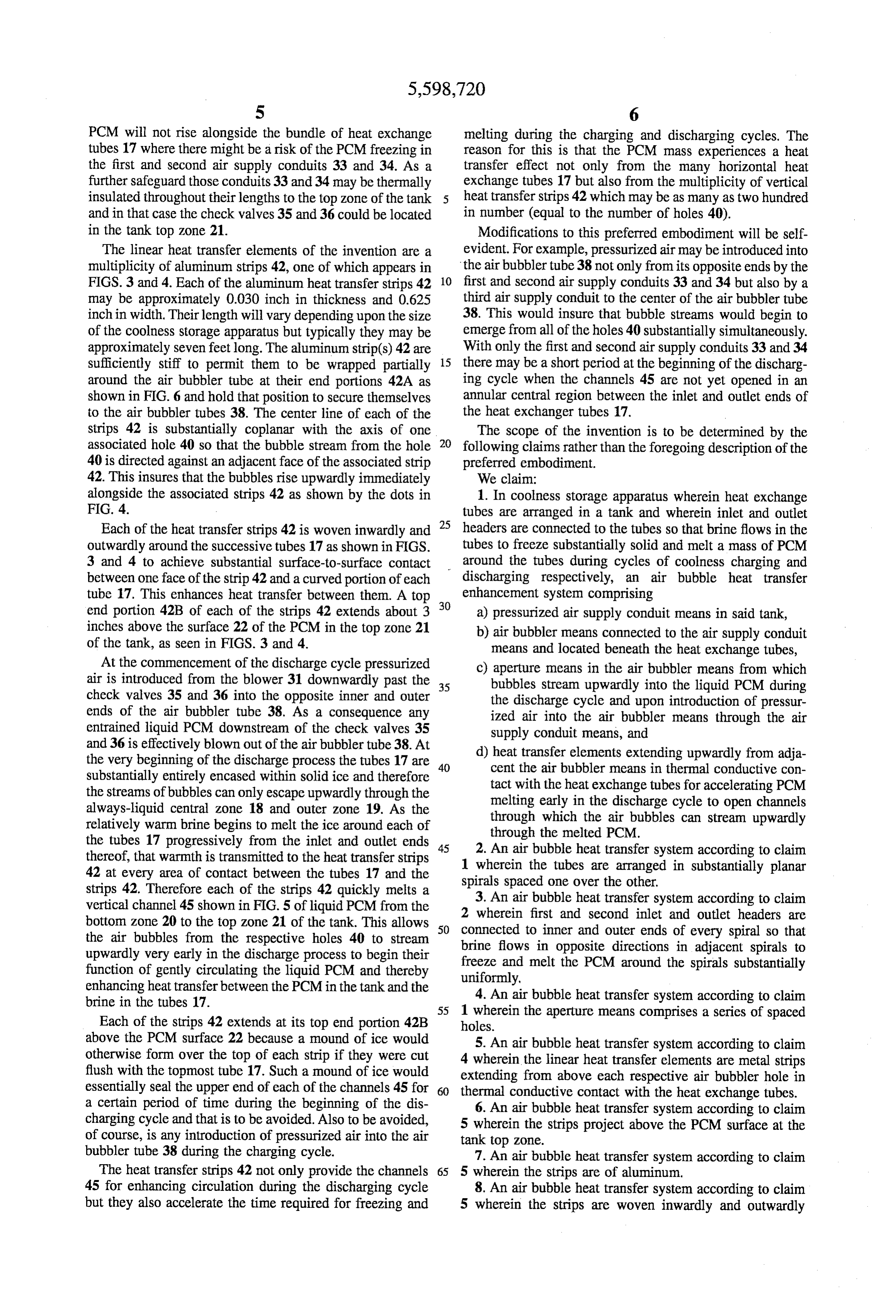
FIG.3 is an enlarged fragmentary side elevation of one of The means for locating the spirals of heat exchange tubes a number of spacer strips holding the heat transfer tubes and 5 within the tank and connecting them to their associated inlet the air bubbler tube in their operating positions within the and outlet headers is fully described in the aforementioned tank; U.S. Pat. No. 4,671,340 and need not be repeated here. That FIG. 4 is a fragmentary elevation directed to the face of patent describes spacer strips, one of which is designated 28 one of the heat transfer strips and the edge of one of the 10 in aFIGS.
in 3 and 4 herein, which hold the spirals in notches 29 snap-in fashion in proper position in relation to the turns associated spacer strips with the various tubes shown in alongside, above and below. That patent also described how place;
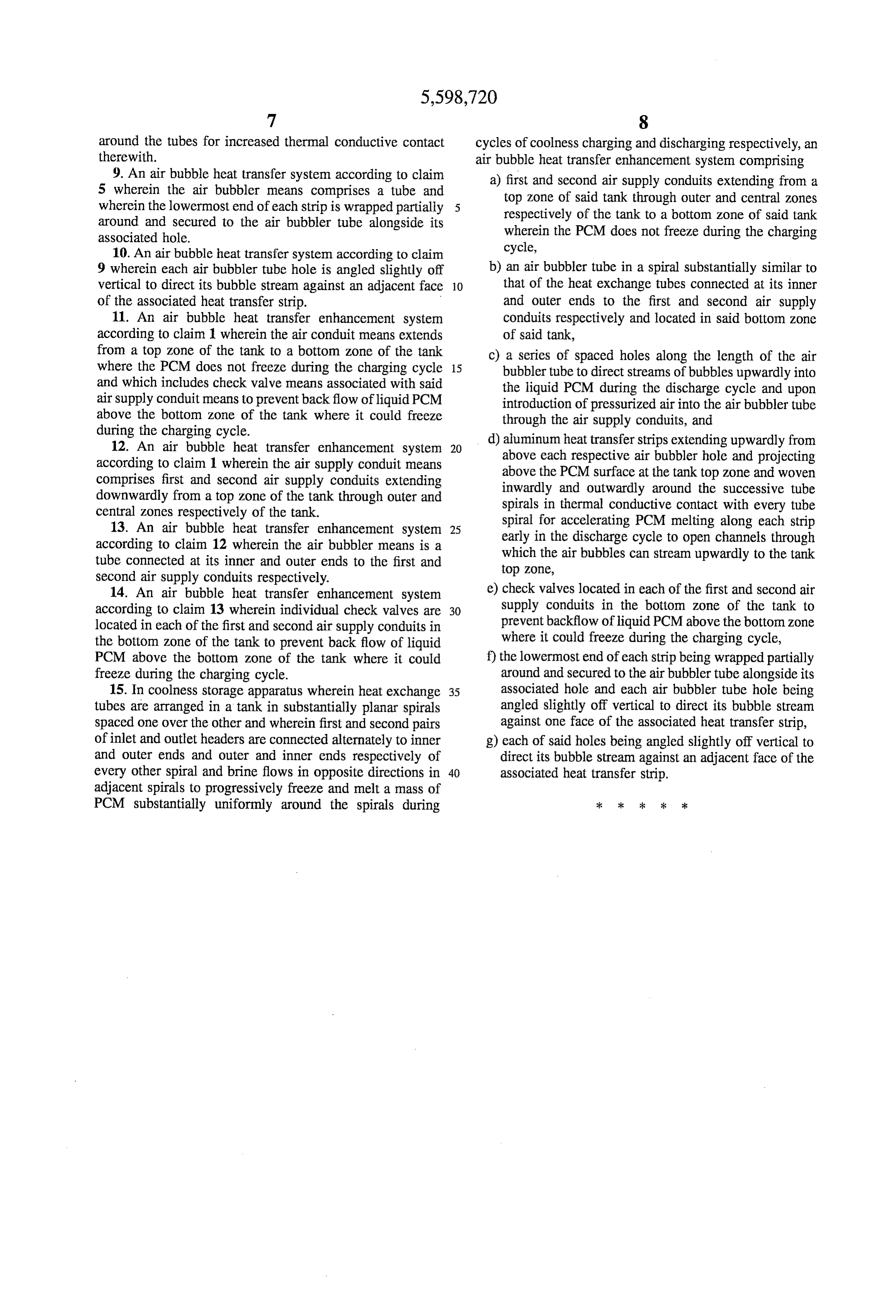
FIG. 5 is an enlarged fragmentary view showing one of the first pair of inlet and outlet headers 23 and 24 and the second pair of inlet and outlet headers 25 and 26 are the strips in section wrapped around one of the heat connected alternately to the inner and outer ends and the exchange tubes in thermal conductive engagement there 15 outer and inner ends respectively of every other spiral. As a with; and consequence brine flows in opposite directions axially FIG. 6 is an enlarged lateral cross section taken through within adjacent spiral tubes to freeze and melt a mass of the air bubbler tube showing one of the holes therein and the PCM progressively around the spirals in a substantially strip associated with that hole wrapped partially around the uniform manner during cycles of coolness charging and air bubbler tube. 20 discharging respectively.
DESCRIPTION OF PREFERRED EMBODIMENT
An alternative design for achieving that counterflow effect is to connect the spiral tubes to the headers so that the brine
Referring first to FIG. 1 the coolness storage apparatus of flows in the same direction axially in all of the tubes but the invention includes a tank 10 having a cylindrical wall 11 25 reverse the direction of the spirals from layer to layer so that of composite thermally insulated construction. An insulated the brine counterflows radially in and out from one layer to base 12 defines the bottom of the tank 10. A circular cover the next, i.e. alternately clockwise in and clockwise out. 13, preferably with a foam insulation core, is disposed over The air bubble heat transfer enhancement system of the the top of the tank 10 and its periphery may be secured to a invention will now be described with reference to each of flange 14 around the upper edge of the tank 10 by a circle 30 FIGS. 1 to 6.
of bolts 15. A typical tank 10 may be approximately eight A regenerative blower 31 is provided which is capable of feet high and over seven feetin diameter. Coiled within it are supplying approximately 5 cubic feet per minute of air at extended lengths of plastic heat exchange tubes 17 in a series about 5 psi, though these figures will vary depending upon of flat spirals forming a vertically extended bundle of tubes. the size of the coolness storage apparatus. The output of this A central Zone 18 within the tank 10 is free of the heat source of pressurized air is carried through a main air inlet exchange tubes 17 and so too is an outer zone 19 around the 35 conduit 32 through the cover 13 and down into the top Zone heat exchange tubes 17 and inside the wall 11 of the tank 10. 21 of the tank. Here it branches into first and second air There may be as many as fifty to sixty individual heat supply conduits 33 and 34. The first air supply 33 extends exchange tube spirals arranged in the tank from a bottom vertically downwardly to the bottom Zone 20 of the tank in Zone 20 thereof up to a level closely below the flange 14 in 40 the central zone 18, while the second air supply conduit 34 a top zone 21 of the tank. In use the tank contains a PCM extends downwardly to the bottom Zone of the tank 20 such as water up to a level indicated by the reference through the outer zone 19. Check valves 35 and 36 are numeral 22 in the top zone 21 and therefore submerging all located in the conduits 33 and 34 respectively in the bottom of the heat exchange tubes 17. zone 20 where the PCM always remains liquid. Circulated through the heat exchange tubes 17 is a brine 45 An air bubbler tube 38 is provided in the bottom Zone 20 such as ethylene glycol. During charging of the coolness of the tank and it is formed in a spiral substantially similar storage apparatus the brine freezes the PCM and during the to that of the heat exchange tubes 17. It is snapped into the discharging cycle the brine melts the PCM. A first brine inlet lowermost notch 29 of the strip(s) 28 as shown in FIG. 3. header 23 extends down the central Zone 18 of the tank 10 The next notch above the air bubbler tube 38 in the strip(s) and returns the brine through a first outlet header 24 in the 50 28 is left vacant and therefore the lowermost heat exchange outer Zone 19 of the tank. A second brine inlet header 25 is tube designated 17A in FIGS. 3 and 4 is spaced well above disposed in the outer zone 19 of the tank alongside the first the air bubbler tube 38. This insures that the freezing effect outlet header 24 with a second outlet header 26 in the central of the lowermost heat exchange tube 17A does not cause zone 18 of the tank 10 alongside the first inlet header 23. freezing of the PCM in the tank bottom Zone 20. The air One of the individual heat exchange tubes designated 55 bubbler tube 38 is connected at its inner and outer ends to the generally by the reference numeral 17 in FIG. 1 appears in first and second air supply conduits 33 and 34 respectively. FIG. 2. The characteristic flat spiral configuration seen in As shown in FIGS. 3 and 6, a series of spaced holes 40 are FIG. 2 is the same in all of the heat exchange tubes 17 in this formed along the length of the air bubbler tube 38 perhaps preferred embodiment. In practice the number of turns in about every 15 inches apart. Typically the holes 40 should be each tube spiral may vary typically from about fifteen to 60 of a diameter of 0.0625 inch (for clarity that diameter is about thirty, and the number shown in FIG. 2 is for illus shown somewhat exaggerated in FIG. 6). As shown particu tration purposes only. The spacing between the turns is larly in FIG. 6 each air bubbler tube hole 40 is angled generally uniform. The outer end of the tube 17N is con slightly off vertical for reasons explained below. nected to the second inlet header 25 and its inner end is When pressurized air is not introduced into the air bubbler connected to the second outlet header 26. The first inlet 65 tube 38 PCM will back flow somewhat into the air bubbler header 23 in the central zone 18 of the tube bundle and the tube but in no event beyond the check valves 35 and 36 in first outlet header 24 in the outer Zone 19 are not connected the first and second air supply lines 33 and 34. Thus the
Page 7
PCM will not rise alongside the bundle of heat exchange melting during the charging and discharging cycles. The tubes 17 where there might be a risk of the PCM freezing in reason for this is that the PCM mass experiences a heat the first and second air supply conduits 33 and 34. As a transfer effect not only from the many horizontal heat further safeguard those conduits 33 and 34 may be thermally exchange tubes 17 but also from the multiplicity of vertical insulated throughout their lengths to the top Zone of the tank heat transfer strips 42 which may be as many as two hundred and in that case the check valves 35 and 36 could be located in number (equal to the number of holes 40). in the tank top Zone 21. Modifications to this preferred embodiment will be self The linear heat transfer elements of the invention are a evident. For example, pressurized air may be introduced into multiplicity of aluminum strips 42, one of which appears in the air bubbler tube 38 not only from its opposite ends by the FIGS. 3 and 4. Each of the aluminum heat transfer strips 42 10 first and second air supply conduits 33 and 34 but also by a may be approximately 0.030 inch in thickness and 0.625 third air supply conduit to the center of the air bubbler tube inch in width. Their length will vary depending upon the size 38. This would insure that bubble streams would begin to of the coolness storage apparatus but typically they may be emerge from all of the holes 40 substantially simultaneously. approximately seven feet long. The aluminum strip(s) 42 are With only the first and second air supply conduits 33 and 34 sufficiently stiff to permit them to be wrapped partially 15 there may be a short period at the beginning of the discharg around the air bubbler tube at their end portions 42A as ing cycle when the channels 45 are not yet opened in an shown in FIG. 6 and hold that position to secure themselves annular central region between the inlet and outlet ends of to the air bubbler tubes 38. The center line of each of the the heat exchanger tubes 17.
strips 42 is substantially coplanar with the axis of one The scope of the invention is to be determined by the associated hole 40 so that the bubble stream from the hole 20 following claims rather than the foregoing description of the 40 is directed against an adjacent face of the associated strip preferred embodiment.
42. This insures that the bubbles rise upwardly immediately We claim:
alongside the associated strips 42 as shown by the dots in 1. In coolness storage apparatus wherein heat exchange FIG. 4. tubes are arranged in a tank and wherein inlet and outlet Each of the heat transfer strips 42 is woven inwardly and 25 headers are connected to the tubes so that brine flows in the outwardly around the successive tubes 17 as shown in FIGS. tubes to freeze substantially solid and melt a mass of PCM 3 and 4 to achieve substantial surface-to-surface contact around the tubes during cycles of coolness charging and between one face of the strip 42 and a curved portion of each discharging respectively, an air bubble heat transfer tube 17. This enhances heat transfer between them. A top enhancement system comprising end portion 42B of each of the strips 42 extends about 3 30 a) pressurized air supply conduit means in said tank, inches above the surface 22 of the PCM in the top zone 21 b) air bubbler means connected to the air supply conduit of the tank, as seen in FIGS. 3 and 4. means and located beneath the heat exchange tubes, At the commencement of the discharge cycle pressurized air is introduced from the blower 31 downwardly past the 35 c) bubbles aperture means in the air bubbler means from which stream upwardly into the liquid PCM during check valves 35 and 36 into the opposite inner and outer the discharge cycle and upon introduction of pressur ends of the air bubbler tube 38. As a consequence any ized air into the air bubbler means through the air entrained liquid PCM downstream of the check valves 35 supply conduit means, and and 36 is effectively blown out of the air bubbler tube 38. At d) heat transfer elements extending upwardly from adja the very beginning of the discharge process the tubes 17 are 40 cent the air bubbler means in thermal conductive con substantially entirely encased within solid ice and therefore tact with the heat exchange tubes for accelerating PCM the streams of bubbles can only escape upwardly through the melting early in the discharge cycle to open channels always-liquid central zone 18 and outer zone 19. As the through which the air bubbles can stream upwardly relatively warm brine begins to melt the ice around each of the tubes 17 progressively from the inlet and outlet ends 45 2. through the melted PCM.
An air bubble heat transfer system according to claim thereof, that warmth is transmitted to the heat transfer strips 1 wherein the tubes are arranged in substantially planar 42 at every area of contact between the tubes 17 and the spirals spaced one over the other. strips 42. Therefore each of the strips 42 quickly melts a 3. An air bubble heat transfer system according to claim vertical channel 45 shown in FIG. 5 of liquid PCM from the 2 wherein first and second inlet and outlet headers are bottom zone 20 to the top zone 21 of the tank. This allows 50 connected to inner and outer ends of every spiral so that the air bubbles from the respective holes 40 to stream brine flows in opposite directions in adjacent spirals to upwardly very early in the discharge process to begin their freeze and melt the PCM around the spirals substantially function of gently circulating the liquid PCM and thereby uniformly, enhancing heat transfer between the PCM in the tank and the 4. An air bubble heat transfer system according to claim brine in the tubes 17. 55 1 wherein the aperture means comprises a series of spaced Each of the strips 42 extends at its top end portion 42B holes.
above the PCM surface 22 because a mound of ice would 5. An air bubble heat transfer system according to claim otherwise form over the top of each strip if they were cut 4 wherein the linear heat transfer elements are metal strips flush with the topmost tube 17. Such a mound of ice would extending from above each respective air bubbler hole in essentially seal the upper end of each of the channels 45 for 60 thermal conductive contact with the heat exchange tubes. a certain period of time during the beginning of the dis 6. An air bubble heat transfer system according to claim charging cycle and that is to be avoided. Also to be avoided, 5 wherein the strips project above the PCM surface at the of course, is any introduction of pressurized air into the air tank top zone.
bubbler tube 38 during the charging cycle. 7. An air bubble heat transfer system according to claim The heat transfer strips 42 not only provide the channels 65 5 wherein the strips are of aluminum.
45 for enhancing circulation during the discharging cycle 8. An air bubble heat transfer system according to claim but they also accelerate the time required for freezing and 5 wherein the strips are woven inwardly and outwardly
Page 8
around the tubes for increased thermal conductive contact cycles of coolness charging and discharging respectively, an therewith. air bubble heat transfer enhancement system comprising 9. An air bubble heat transfer system according to claim a) first and second air supply conduits extending from a 5 wherein the air bubbler means comprises a tube and top zone of said tank through outer and central Zones wherein the lowermost end of each strip is wrapped partially respectively of the tank to a bottom Zone of said tank around and secured to the air bubbler tube alongside its wherein the PCM does not freeze during the charging associated hole.
10. An air bubble heat transfer system according to claim cycle, 9 wherein each air bubbler tube hole is angled slightly off b) an air bubbler tube in a spiral substantially similar to vertical to direct its bubble stream against an adjacent face 10 that of the heat exchange tubes connected at its inner of the associated heat transfer strip. and outer ends to the first and second air supply 11. An air bubble heat transfer enhancement system conduits respectively and located in said bottom Zone according to claim 1 wherein the air conduit means extends of said tank, from a top Zone of the tank to a bottom zone of the tank c) a series of spaced holes along the length of the air where the PCM does not freeze during the charging cycle 15 bubbler tube to direct streams of bubbles upwardly into and which includes check valve means associated with said the liquid PCM during the discharge cycle and upon air supply conduit means to prevent backflow of liquid PCM introduction of pressurized air into the air bubbler tube above the bottom Zone of the tank where it could freeze through the air supply conduits, and during the charging cycle. d) aluminum heat transfer strips extending upwardly from 12. An air bubble heat transfer enhancement system 20 above each respective air bubbler hole and projecting according to claim 1 wherein the air supply conduit means above the PCM surface at the tank top Zone and woven comprises first and second air supply conduits extending inwardly and outwardly around the successive tube downwardly from a top Zone of the tank through outer and spirals in thermal conductive contact with every tube central zones respectively of the tank. spiral for accelerating PCM melting along each strip 13. An air bubble heat transfer enhancement system 25 early in the discharge cycle to open channels through according to claim 12 wherein the air bubbler means is a which the air bubbles can stream upwardly to the tank tube connected at its inner and outer ends to the first and second air supply conduits respectively. top Zone, 14. An air bubble heat transfer enhancement system e) check valves located in each of the first and second air according to claim 13 wherein individual check valves are 30 supply conduits in the bottom Zone of the tank to located in each of the first and second air supply conduits in prevent backflow of liquid PCM above the bottom zone the bottom Zone of the tank to prevent back flow of liquid where it could freeze during the charging cycle, PCM above the bottom Zone of the tank where it could f) the lowermost end of each strip being wrapped partially freeze during the charging cycle. around and secured to the air bubbler tube alongside its 15. In coolness storage apparatus wherein heat exchange 35 associated hole and each air bubbler tube hole being tubes are arranged in a tank in substantially planar spirals angled slightly off vertical to direct its bubble stream spaced one over the other and wherein first and second pairs against one face of the associated heat transfer strip, of inlet and outlet headers are connected alternately to inner g) each of said holes being angled slightly off vertical to and outer ends and outer and inner ends respectively of direct its bubble stream against an adjacent face of the every other spiral and brine flows in opposite directions in 40 associated heat transfer strip. adjacent spirals to progressively freeze and melt a mass of
PCM substantially uniformly around the spirals during
Provenance
- Collection
- Cited prior art
- Original PDF
- patentimages.storage.googleapis.com →
- Filed
- 1995-08-02
- Pages
- 8
- Method
- pdftotext (the PDF's own text layer) + pdftoppm 300dpi page scans
- Source
- Google Patents bibliographic record
- Granted
- 1997-02-04
- Inventors
- Mark M. MacCracken; Brian M. Silvetti; Jose R. Bonet; Calmac Manufacturing Corp
- Transcribed from
- patentimages.storage.googleapis.com →