patent · US4609036
Bulk heat or cold storage device for thermal energy storage compounds
2 September 1986
Page 1 — bibliographic record
United States Patent (19) 11 Patent Number: 4,609,036 Schrader 45) Date of Patent: Sep. 2, 1986 54 BULK HEAT OR COLD STORAGE DEVICE 57 ABSTRACT
FOR THERMAL ENERGY STORAGE
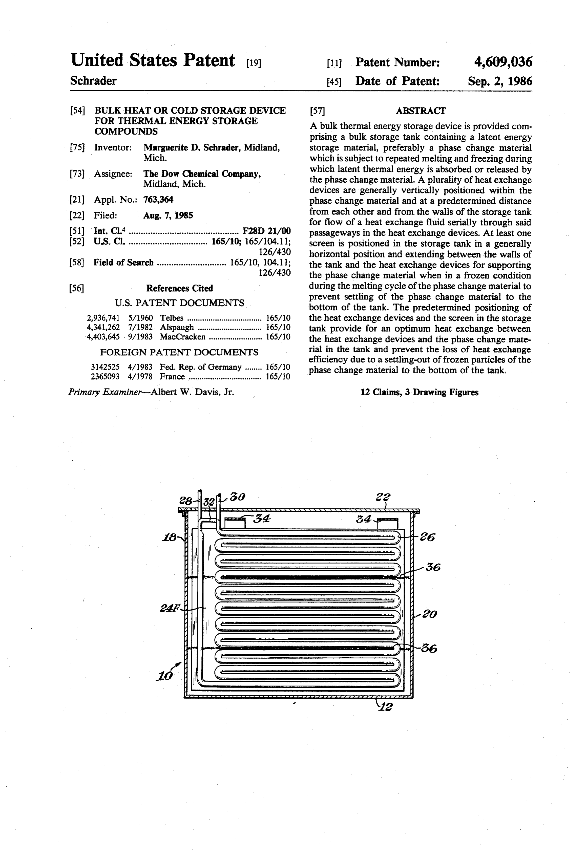
COMPOUNDS A bulk thermal energy storage device is provided com prising a bulk storage tank containing a latent energy 75 Inventor: Marguerite D. Schrader, Midland, storage material, preferably a phase change material Mich. which is subject to repeated melting and freezing during 73 Assignee: The Dow Chemical Company, which latent thermal energy is absorbed or released by Midland, Mich. the phase change material. A plurality of heat exchange devices are generally vertically positioned within the 21) Appl. No.: 763,364 phase change material and at a predetermined distance 22 Filed: Aug. 7, 1985 from each other and from the walls of the storage tank for flow of a heat exchange fluid serially through said 51 Int, C. .............................................. F28D 21/00 passageways in the heat exchange devices. At least one (52) U.S. C. ................................. 165/10; 165/104.11; screen is positioned in the storage tank in a generally 126/430 horizontal position and extending between the walls of (58) Field of Search ............................. 165/10, 104.11; the tank and the heat exchange devices for supporting 126/430 the phase change material when in a frozen condition 56) References Cited during the melting cycle of the phase change material to
prevent settling of the phase change material to the bottom of the tank. The predetermined positioning of 2,936,741 5/1960 Telbes ............. wa 165/10 the heat exchange devices and the screen in the storage 4,341,262 7/1982. Alspaugh. ... ... 165/10 tank provide for an optimum heat exchange between 4,403,645 - 9/1983 MacCracken ......................... 165/10 the heat exchange devices and the phase change mate FOREIGN PATENT DOCUMENTS rial in the tank and prevent the loss of heat exchange efficiency due to a settling-out of frozen particles of the 3142525 4/1983 Fed. Rep. of Germany ........ 65/10 phase change material to the bottom of the tank. 23.65093 4/1978 France .................................. 165/10
Primary Examiner-Albert W. Davis, Jr. 12 Claims, 3 Drawing Figures
Page 2
Drawing sheet — no readable text.
Page 3
Drawing sheet — no readable text.
Page 4
domestic and commercial installations; applicability to a
BULK HEAT OR COLD STORAGE DEVICE FOR large number of end uses, and low toxicity. THERMAL ENERGY STORAGE COMPOUNDS Preferred phase change compositions comprise a mixture of hydrated CaCl2 with other salts, to modify
BACKGROUND OF THE INVENTION 5 the semi-congruent melting behavior of the hydrated The present invention resides in a bulk thermal en ferredCaCl2 to a congruently melting composition. Such pre ergy storage device. More particularly, the invention Pat. Nos. compositions are disclosed, for example, in U.S. resides in a bulk thermal energy storage device compris 4,272,390, and 4,412,931; U.S. application Ser. ing a container or tank for storing a hydrated phase O No. 364,159 filed Mar. 31, 1982; U.S. application Ser. No. 504,763, filed June 15, 1983, and U.S. application change material (PCM) which is subject to repeated Ser. No. 540,726 filed Oct. 11, 1983, all of which are freezing and melting cycles during which latent thermal incorporated herein by reference. energy in the composition is released or, alternatively, The storage of phase change materials has also been thermal energy is absorbed by the composition. At least extensively investigated in past years since containers one heat exchange device is positioned within the PCM 15 for PCM's must be able to withstand the physical inside of the bulk container in a substantially vertical stresses accompanying the freeze-thaw cycles of the position. The heat exchange device has a flow passage PCM over a long period of time. Reference is made to or channel therein for flow of a heat exchange fluid report ORO/5217-8 of November, 1978 entitled through the channel. The heat exchange device is posi "Macro Encapsulation of Phase Change Materials,' tioned in the container in a spaced relationship to the 20 authored by G. A. Lane et al. The study showed that interior walls of the container to permit convection containers for hydrated PCM's must be constructed of a currents to flow through the spaces provided between durable material and must be reliably leak-proof to the interior wall surfaces off the bulk container and the liquids and vapors. Since PCM's are generally corro exterior wall surfaces of the heat exchange device dur sive, the containers must also be constructed of a mate ing the melting cycle of the PCM. At least one screen is 25 rial which is resistant to such corrosion. positioned in the bulk container extending substantially Containers made of stainless steel or other corrosion horizontally and at a distance from the bottom of the resistant metals or alloys have shown themselves to be container and adjacent to the heat exchange device for effective over long periods of time. Although the cost supporting solid crystalline particles of the PCM which of metal containers of a small size such as are normally are present at the onset of the melting cycle of the PCM. 30 employed in residential housing is prohibitive, such The supporting screen prevents any solid crystalline containers are cost effective when employed as large particles from settling or falling to the bottom of the bulk storage containers for use in large commercial container, during the onset of the melting cycle, where installations such as, for example, office buildings, cold the crystalline particles are no longer sufficiently ex 35 storage buildings, and the like. A large thermal energy storage system employing a PCM for an off-peak air posed to a direct contact with the convection currents conditioning of the melted PCM to melt such solid crystalline parti Dudley under system is described in a report by James C. cles. The screen supports the solid particles in a position GI27976/TR72/8.theThedesignation report is
entitled "Thermal En adjacent to the heat exchange device and above the ergy Storage Unit for Air Conditioning Systems. Using container bottom such that the convection currents of the molten PCM can contact the solid particles until the National Science Foundation Grant No. GI27976.the 40 Phase Change Materials', and was supported by
solid particles have absorbed sufficient thermal energy this report, J. C. Dudley describes a unit sized for a two from the molten PCM to undergo a phase change from ton peak load and a one ton daily average load. The unit a solid to a molten state.
had a rated capacity of 100,000 BTU. The heat transfer
DESCRIPTION OF THE PROR ART 45 surface was a stack of 42 horizontally positioned alumi num sheets, spaced one inch apart, with embedded re
Thermal energy storage materials are well known in frigerant the art and include phase change materials capable of conditioning passages. The unit was designed for use in air and coolness storage systems or in space storing latent thermal energy by means of a reversible heating storage systems with suitable choices of phase change of state, or phase change, in the storage mate 50 change materials.
rial. Latent heat materials have the advantage of higher The drawback in large systems such as described by heat storage capacity, thus allowing a reduction in size J. C. Dudley is that the heat exchanger sheets are and weight in the thermal storage unit; lower storage stacked horizontally with a uniform one inch spacing temperature; less insulation, and higher collection effi between adjacent sheets. Such arrangement does not ciency. 55 allow for a uniform distribution of the thermal energy Phase change materials which may be employed in being transfered to or withdrawn from the phase the practice of the present invention are various hy change composition. Moreover, very little convection drated salt compositions such as are well known in the current flow can take place between the horizontally art. A number of such PCM's have been identified by G. spaced heat exhanger sheets thus retarding or prevent A. Lane in Volume I of "Solar Heat Storage: Latent ing a melting of the phase change material between the Heat Materials', published 1983, CRC Press, Boca Ra stacked sheets.
ton, Fla. Generally, a maximum thermal energy exchange Of particular interest are thermal energy storage ma takes place between the heat exchanger sheets and the terials which have phase transition temperatures in the phase change material in the upstream sheets i.e. the range of from greater than about zero degrees up to 65 sheets nearest the inlet for the heat exchange fluid flow about 140°C. Included within this temperature range is ing through the sheets. A relatively reduced thermal the material CaCl2.6H2O, which is of particular interest energy exchange takes place between the sheets and the because of its low cost; ready availability for large scale phase change material at the downstream end, i.e. near
Page 5
est the outlet end of the system. It will be apparent that ing latent heat energy during the freezing cycle of the the phase change of a PCM from a frozen to a molten material, a plurality of generally planar heat transfer state (for cooling purposes, i.e., air-conditioning or re device positioned in said container in a substantially frigeration) will take place more rapidly nearer the inlet vertical orientation, said heat transfer devices being to the first, in line, heat exchange sheets where the connected to each other in series and spaced in a prede thermal energy input is at its highest, whereas the ther termined variable relationship with respect to each mal energy transfer in the heat exchange sheets nearest other and the side wall of the container, for flow of a the outlet is at a minimum. heat exchange fluid through said heat and transfer de
SUMMARY OF THE INVENTION
vices, and a screen positioned in a substantially horizon 10 tal position in said container, said screen being arranged
The problems associated with storage devices of the in a spaced position above the bottom of the container. prior art have now been overcome with the bulk ther The present invention also resides in a storage device mal energy storage device of the present invention. comprising a container having a top wall, a bottom A particular object of the invention resides in a ther wall, and opposed side walls, a hydrated phase change mal energy storage device comprising a container for 15 material contained within the container, wherein said storing a phase change material and a plurality of plate phase change material passes through repeated cycles of like heat exchange devices positioned within the con melting and freezing during which the phase change tainer in a substantially vertical orientation and spaced material absorbs and releases latent heat energy, a plu at a predetermined distance from each other and from rality of heat transfer devices positioned in said con the container walls. 20 tainer in a substantially vertical orientation, each heat A further object of the invention resides in a thermal transfer device having a plate-like shape with an inter energy storage device comprising a container for stor nal passageway for flow therethrough of said heat ex ing a phase change material, a plurality of plate-like heat change fluid, an inlet conduit for said heat exchange exchange devices positioned within the PCM and inside fluid connected to an inlet of said passageway in a first of the container in a substantially vertical orientation, 25 of said series of heat transfer devices, an outlet conduit and at least one screen in said container extending sub for said heat exchange fluid connected to an outlet of stantially horizontally and at a distance from the bottom said passageway in the last of said series of heat transfer of the container and adjacent to the heat exchange de devices, and connecting conduits for serially connect vices for supporting solid crystalline particles of the ing the passageways of the heat transfer devices to each PCM during the melting cycle of the PCM. 30 other, and wherein the first heat transfer device is Advantages of the storage device of the invention are spaced from its adjacent container wall and from a that the tank is of a size to hold a large quantity of a succeeding heat transfer device in said series by a dis PCM, i.e. in excess of 100 gal, and constructed of a tance which is greater than the distances of the interme material of sufficient strength e.g. inch carbon steel diate heat transfer device from each other and which is plate, to allow filling and sealing of the tank before 35 also greater than the distance of the last heat transfer shipment of the storage device to the site of installation. device from its adjacent container wall and from a pre A further advantage of the storage device of the ceding heat transfer device of said series, and a screen invention is that the tank is hermetically sealed to pre positioned in said container in a substantially horizontal vent the loss of water vapor and therefore a change in position above the bottom wall of the container and the amount of hydration of the PCM. Hermetic sealing adjacent to the heat transfer device for supporting solid of the tank also prevents internal corrosion of the tank crystalline particles of the phase change material which components by excluding oxygen. are present during the melting of the phase change Another advantage of the storage device of the in material.
vention resides in the substantially vertical orientation The invention additionally resides in a method of of the heat transfer or heat exchange plates within the 45 storing energy in a container containing a hydrated tank which allows for a convection current flow of the phase change material, comprising the steps of position molten PCM during the melting cycle of the PCM. ing a plurality of generally planar heat transfer devices An advantage of the invention also resides in the in a substantially vertical and submerged position into predetermined variable spacing of the plates from each said phase change material in said container such that a other and from the tank walls to allow for a maximum 50 first of said series of heat transfer devices is more widely or optimum energy transfer between the plates and the spaced from an adjacent side wall of said container and phase change material. from an adjacent intermediate heat transfer device than The size of the storage device of the invention is the spacing of a last of said series of heat transfer de preferably designed within limits to allow for ease of vices from an adjacent side wall of said container and movement of the device into a building and for ease of 55 said adjacent intermediate heat transfer device, posi installation, servicing or remodeling. tioning at least one screen in said container in a substan The storage device of the invention can be sized for tially horizontal and spaced position above a bottom any desired cycling interval. Preferably, and depending wall of the container and adjacent to the heat transfer on the ultimate use of the device, the cycling time is for devices, hermetically sealing said container, and flows a 24 hour period during which the PCM undergoes a 60 ing a heat exchange fluid serially through said heat phase transition from a molten to a frozen state and back transfer devices for melting or freezing said phase again from a frozen to a molten state. change material and for absorbing and releasing latent More specifically, the present invention resides in a heat energy from said phase change material. storage device comprising a container having a bottom wall, a top wall, and at least one side wall, a hydrated 65 BRIEF DESCRIPTION OF THE DRAWINGS phase change material contained in said container and Having generally described the invention herein capable of absorbing latent heat energy during the melt above, reference will now be made to the accompany ing cycle of the material and which is capable of releas ing drawings for a more detailed description of the
Page 6
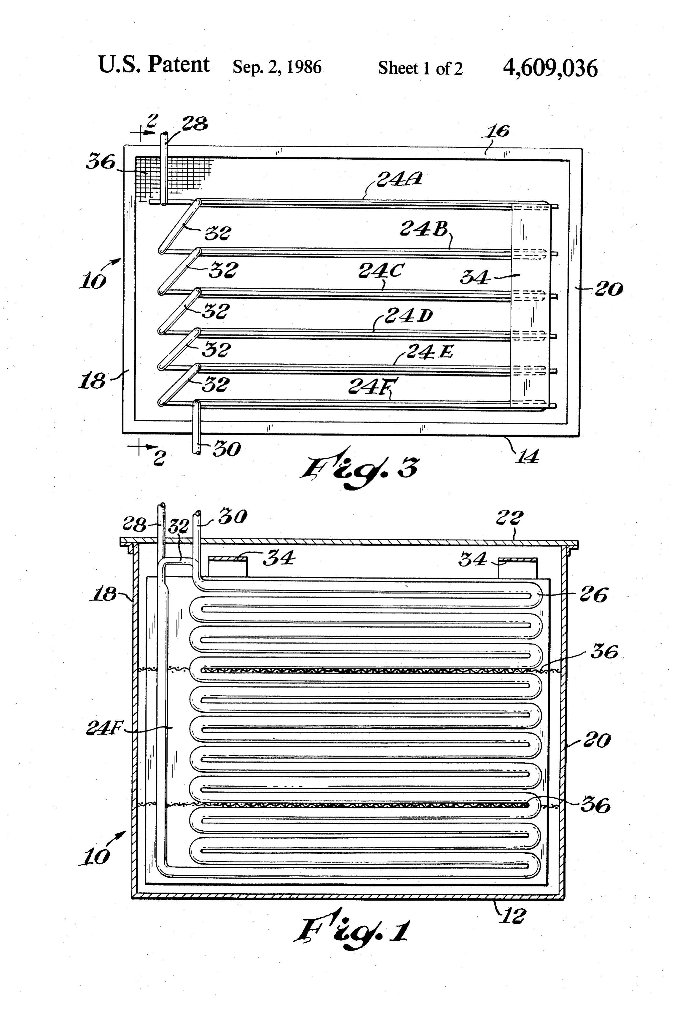
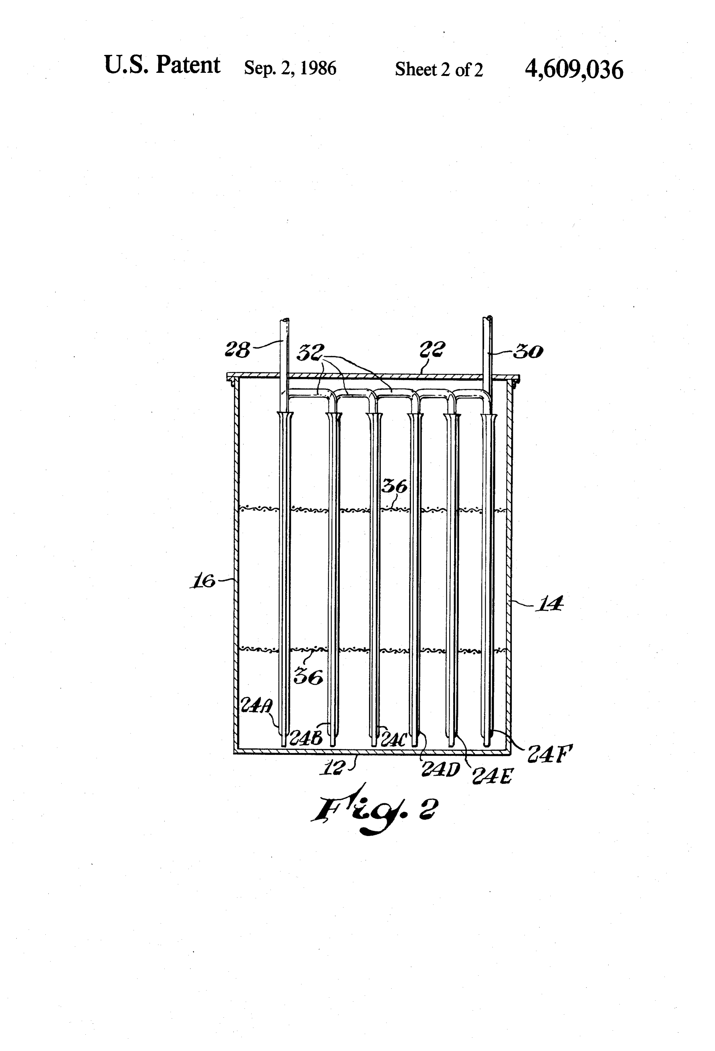
invention. A preferred embodiment of the invention is on whether the storage device is intended to be used as illustrated in the attached drawings in which: a “heat' or as a “cold' storage device. Preferred PCM's FIG. 1 is a planar side view, in crosssection, of a bulk which may be usefully employed in the storage device thermal energy storage device comprising a bulk stor of the invention are those which melt over a broad age tank or container having a heat exchange device 5 temperature range and which can be used for (1) the positioned in the container. storage of "coolness' over a temperature range of from FIG. 2 is a planar front view, in crosssection, of the about 5' to about 17°C.; (2) for the storage of "heat' storage device of FIG. 1 but showing, in particular, a over a temperature range of from about 25 to about 50 plurality of vertical heat exchange devices positioned in C., and (3) as a buffer or heat sink to moderate diurnal a predetermined, spaced relationship with respect to 10 swings in the ambient temperature range of from about each other and, with respect to the front and rear walls 17 to about 25 C.
of the container, and a pair of horizontally spaced A plurality of heat exchange devices (24A-24F) are screens in the container. positioned in the tank in a substantially vertical orienta FIG. 3 is a top view, in cross-section, of the storage tion. The devices are submerged in the PCM and are device of FIG. 1, but showing, in particular, the inlet, 15 thus in intimate thermal heat exchange contact with the outlet and connecting conduits connecting the heat PCM. The heat exchange devices are preferably of the exchange devices, the horizontally extending screen, type in which two metal plates or sheets are welded and the predetermined spacing between the plates. together along their outer edges and along a pair of
DETAILED DESCRIPTION OF THE
spaced, serpentine, pathways. The space between the 20 welds is subsequently inflated under high fluid pressure
INVENTION to form a serpentine or convoluted passageway or con With particular reference to the drawings, there is duit (26). Alternatively, two metal plates can be illustrated a bulk thermal energy storage device com stamped prior to welding to provide a serpentine pas prising a bulk storage tank or container (10). The stor sageway between the plates. Such heat exchange plates age tank can be constructed of any suitable material 25 generally provide for a somewhat better heat transfer provided that the tank has sufficient strength to contain due to absence of dead spaces in the welded plates. a relatively large quantity of a reversible liquid/solid Moreover, such prestamped and welded plates are bet phase change material (PCM) over a long period of ter able to withstand internal pressures of a heat ex time. Materials such as metals, metal alloys, metal/plas change fluid and stresses due to expansionary and con tic/metal laminates, synthetic resinous materials, plastic 30 tractionary forces on the metal plates brought about by lined concrete, for example, may be suitably employed the melting and freezing cycles of the phase change in the construction of the storage tank. Metals or metal material.
alloys are preferred, particularly those metals or metal An inlet conduit (28) for a liquid or gaseous heat alloys, which are resistant to corrosion such as stainless exchange medium is welded to one end of the passage steel, or carbon steel and the like. The term bulk storage 35 way (26) which terminates in an opening (not shown) at tank herein signifies tanks which contain PCMs in an edge of the heat exchange plate. An outlet conduit amounts generally greater than about 100 gallons. (30) for the heat exchange medium is welded to the Tanks having a capacity of less than about 100 gallons other end of the passagway (26) which terminates in an are not economically attractive particularly when con opening (not shown) at an edge of the heat exchange structed of a metal or metal alloy. Storage tanks under 40 plate. Preferably, the inlet and outlet of the passageway consideration here have a capacity of about 100 gallons terminate at the same edge of the heat exchange plate so and up to 20,000 gallons, or greater. that the inlet and outlet conduits (28,30) can be conve The storage tank (10) preferably is rectangular in niently connected to the plate by passing the conduits shape and comprises a bottom wall (12), a front wall 14, through the openings in the lid as is more clearly shown rear wall 16 and opposed side walls 18 and 20. It is 45 in the drawings. The inlet and outlet conduits are subse apparent that the storage tank may be constructed of quently sealed to the lid by means of sealing washers, or other geometric shapes such as of a square, circular or the like, to prevent the loss of water vapor through the oval shape. The tank is provided with a cover or lid (22) space between the openings in the lid and the inlet and which is preferably made of the same material as the outlet conduits. The heat exchange plates of the afore tank and which can be secured to the tank as by weld 50 described construction are preferred since they have ing, bolting, or any other convenient manner. The con great structural strength, superior heat exchange trans tainer should be hermetically sealed to prevent the loss fer capacity which extends beyond the passageway (26) of water from the hydrated PCM. Such loss of water is into the welded portions of the plates, and are economi effectively prevented where the lid is welded to the cal to manufacture. It will be apparent, of course, that container. However, it is generally more convenient to 55 an effective heat exchange transfer may also be affected secure the lid to the container body by bolting the lid to with a tube bundle constructed of a plurality of individ a flange provided on the open end of the container, in a ual tubes such as is conventionally employed in high manner well known, so that the lid can be removed temperature steam heat exchangers. from the container, if it should become necessary to The heat exchange plates 24A through 24F are inter service the device, i.e. the heat exchange plates, conduit connected by connecting or bridging conduits (32). connections, screens, and the like, during the life of the Accordingly, the inlet conduit (28) is connected to a storage device. If the lid is bolted to the container open first of a series of heat exchange plates (24A) while the ing, it is necessary to provide a suitable sealing gasket outlet conduit (30) is connected to the last of the series between the container flange and the lid to prevent the of heat exchange plates (24F). The outlet end of the escape of water vapor from the container. The sealing 65 passageway (26) of plate (24A) is connected by means gasket may be made of any suitable material, such as are of the connecting conduit (32) to an inlet end of the commonly employed in Industry. The tank is filled with second heat exchange plate (24B) and so on. Accord a suitably formulated phase change material depending ingly, the plates (24A) through (24F) are serially con
Page 7
nected to each other such that the heat exchange me plate. The molten PCM adjacent to the outer surfaces of dium can flow from the inlet conduit (28) sequentially each plates will begin to flow along channels between through the passageway (26) of each plate and out of the outer surfaces of the plates and the PCM which is the outlet conduit (30) for subsequent utilization of the still in a frozen state. the convection current set up by heat or cold energy from the heat exchange medium. 5 the molten PCM gradually releases monolithic portions The plates are spaced at a predetermined distance from of the still frozen PCM midway between the plates. As each other and are conveniently attached as, for exam these frozen portions break up into smaller blocks or ple, by welding, to a frame member or a pair of frame particles, they tend to sink or settle to the bottom of the members (34) positioned at opposite ends of the plates. tank where they collect as a sediment of still frozen The frame members (34) may be provided with lifting 10 particles. Since the convection current of molten PCM hooks or handles (not shown) to allow for a removal of can no longer circulate as freely over the surfaces of the the entire assembly of heat exchange plates from the frozen blocks or particles of the PCM at the bottom of tank. the tank, they remain permanently as an inoperative From FIGS. 2 and 3, it will be seen that the plate residual PCM at the bottom of the tank during each (24A) is more widely spaced from plate (24B) than is the 15 succeeding cycle of conversion of the PCM from a spacing of plate (24B) from plate (24C) and so on. frozen to a molten state. This condition effectively re Stated another way, the spacing between the plates duces the energy storage capacity and efficiency of the (24A) through (24E) decreases gradually between the system.
plates, with the greatest distance being between the first To prevent the accumulation of frozen PCM particles plates (24A) and (24B) and with the smallest distance 20 at the bottom of the tanks, one or more porous supports being between the last plates (24E) and 24F). The rela or screens (36) are provided in the tank. The screens are tive spacing between the plates is determined to com positioned in a substantially horizontal position and at a pensate for a relatively greater heat exchange transfer spaced distance from each other and from the bottom of which takes place between the heat exchange medium the tank. As particularly shown in FIG. 2, two screens entering the passageway (26) of the first plate (24A) at 25 (36) are provided in the tank each extending over the inlet conduit (28) and the relatively lower heat ex entire area of the tank bounded by the front, rear and change transfer which takes place between the heat side walls and between the heat exchange plates. Ad exchange medium leaving the passageway (26) of the vantageously, the bottom screen may be positioned at a last plate (24F) at outlet conduit (30). By way of exam distance of about the depth of the PCM from the ple, if the phase change material in the tank is in a mol 30 bottom of the tank. The upper screen may be positioned ten state and it is desired to extract the latent heat en at a distance of about the depth of the PCM from the ergy from the PCM for heating purposes, a relatively bottom of the tank. Accordingly, the screens are sub cool heat exchange medium passing through the pas stantially equally spaced from each other and from the sageways in the plates will absorb a greater amount of bottom of the tank. If it is desired to employ more than heat energy from the PCM as it passes through the first 35 two screens, it will be apparent that the screens can be plate (24A). Additional heat energy is absorbed by the arranged so that they are spaced from each other and heat exchange medium in a gradually decreasing from the bottom of the tank at substantially equal dis amount as it passes through the passageways in each tances for most effective performance. succeeding plate (24B) through (24F). Energy absorp The screens are preferably made of a metal wire mesh tion will therefore gradually decline as the heat ex having a mesh size of from 2.83 mm to about 12.7 mm change medium flowing through the plates heats up. By (U.S. Sieve Series) and are attached to the walls of the the time that the heat exchange medium leaves heat tank and/or the plates by any convenient method such exchange plate (24F) through conduit (30), it will have as, for example, by tack welding. The screens are pref absorbed a sufficient amount of thermal energy from the erably constructed of a non-corrosive metal or metal PCM to allow it to be effectively utilized in the subse 45 alloy. Other types of screens or porous supports may be quent transfer of this thermal energy for heating pur employed in the practice of the invention such as, for poses. Since the greatest amount of energy transfer example, metal plates provided with a multiplicity of takes place at plate (24A) it has been found that by drilled or stamped holes. Such metal plates would pref. properly spacing the plates with respect to each other erably be provided with openings having a size of about and with respect to the side walls of the tank, a more 50 3 mm to about 12.5 mm in diameter or on the square and effective and a more uniform transfer of energy is an open area of from about 50 to 75 percent of the total achieved between the plates and the PCM in the tank. area of the sheet. The thickness of the screen is some In effect, the presence of a greater volume of the PCM what dependent on the size of the tank; the size of the in the space between the plate 24A and rear wall of the heat exchange plates, and the number of screens that are tank and between plates (24A) and 24B) will insure that 55 employed in the tank.
the PCM will crystallize or freeze at about the same During the melting cycle of the PCM, blocks or parti time as the PCM which is present in the space between cles of the still frozen PCM which are released from the plates 24F and front wall of the tank and between plates heat exchange plates are effectively supported and re (24E) and (24F) where a relatively smaller transfer of tained on the screen. While they are supported and energy between these plates and the PCM takes place. 60 retained on the screens, convection currents of the mole Freezing or crytallization of the PCM therefore takes ten PCM continues to circulate freely through the place uniformly throughout the tank and is advanta screens and over the frozen PCM particles until com geously completed at about the same time interval. plete melting of the particles is achieved. Smaller parti In the case where the PCM in the tank is in a crystal cles dropping through the holes in the screen are held in lized or frozen condition and the heat exchange medium 65 suspension by the upwardly flowing molten PCM until is at a relatively high temperature, the heat exchange they are dissolved in the melt. The screens are thus medium flowing through the plates will initially melt effective in retaining frozen PCM particles in position the PCM crystals that are nearest or adjacent each between the heat exchange plates and the walls of the
Page 8
tank until the convection current of molten PCM causes buffer in systems where waste heat is being generated a complete melting of the particles. during one time frame, and thermal energy at the same
EXAMPLE
temperature level is required during another time frame.
The unit can be designed to perform a complete char
A storage tank was constructed from inch carbon ge/discharge cycle (melt/freeze) over any desired time steel plate having a width of 28 inches; a height of 49 period. Usually, one complete melt/freeze cycle is per inches and a length of 50 inches. Five heat exchange formed over a 24 hour time period.
plates were connected to a frame member and inserted The tank is designed to be filled and sealed before into the tank. Each heat exchange plate consisted of two shipping to a site of installation, thereby allowing for flat sheets of carbon steel having a height of 36 inches O better quality control of the PCM and improved con and a length of 47 inches. The sheets are resistance struction of the unit at the manufacturing site. welded to each other to form a seam. The space be The unit can be coupled to a water loop, as a heat tween the seam was inflated to form a pillow-effect in exchange medium or to a loop of any other heat transfer which the inflated portion had a thickness of 0.4 inch. fluid, liquid or gaseous. Loops to which the unit of the The inflated portion formed a passageway for a heat 5 invention can be advantageously employed include exchange fluid. The heat exchange plates are of a type water source heat pump loops; commercial air condi commercially available from Paul Mueller Co. under tioning loops or waste hot water recovery, for example. designation 5D-14/14 C. Steel: 36 inx47 in SW., and What is claimed is:
are generally identified as temp-plates. 1. A storage device comprising a container having a The five plates were inserted into the tank and con 20 bottom wall, a top wall, and at least one side wall, a nected in series so that water entering and flowing hydrated phase change material contained in said con through the first plate is discharged and fed to a second tainer and capable of absorbing latent heat energy dur plate, the discharge from the second plate is fed to the ing the melting cycle of the material and which is capa third plate, etc. The inlet conduit to the first plate and ble of releasing latent heat energy during the freezing the outlet conduit from the fifth plate were extended 25 cycle of the material, a plurality of generally planar heat through the tank cover and connected to a tempered transfer devices positioned in said container in a sub water loop in which the water temperature varied from stantially vertical orientation, said heat transfer devices 50 F. to 105 F. being connected to each other in series and spaced in a The heat exchange plates were spaced in the tank for predetermined variable relationship with respect to maximum heat transfer between the PCM and the 30 each other and the side walls of the container, for flow plates. Plate no. 1 was spaced 3.0 inches from the tank of a heat exchange fluid through said heat transfer de wall; plate no. 2 was spaced 5.4 inches from plate no. 1; vices, and a screen positioned in a substantially horizon plate no. 3 was spaced 4.7inches from plate no. 2; plate tal position in said container, said screen being arranged no. 4 was spaced 4.5 inches from plate no. 3; plate no. 5 in a spaced position above the bottom of the container. was spaced 4.3 inches from plate no. 4; and 2.0 inches 35 2. The storage device of claim 1, wherein the housing from the tank wall. All distances are measured from the has front and rear walls, top and bottom walls, and center of the plates. opposed side walls, said heat transfer devices each hav A screen having mesh openings of inch and con ing a plate-like shape with an internal passageway for structed of nickel was installed at two levels horizon flow therethrough of said heat exchange fluid, an inlet tally across the tank. The first screen was installed at a conduit for said heat exchange fluid extending through distance of 10 inches from the bottom of the tank and one of said walls of said container and connected to an the second screen at a distance of 25 inches from the inlet of said passageway in a first of said series of heat. bottom of the tank. The screens were tack welded to the transfer devices, an outlet conduit for said heat ex tank walls and the heat exchange plates. The tank was change fluid extending through one of said walls of said then filled with 225 gallons of a hydrated CaCl2 PCM 45 container and connected to an outlet of said passageway and hermetically sealed by bolting a lid to the gasketed in the last of said series of heat transfer devices, and tank. The tank was tested for leaks to make sure that the connecting conduits for serially connecting the passage PCM was hermetically sealed within the tank. ways of said heat transfer devices to each other, and Water at a temperature of 55 F. was fed through the wherein the first of said series of heat transfer devices is inlet conduit connected to the first plate in the tank at a 50 spaced from its adjacent container wall and from a rate of 1000 lb/hr. Exit water temperature varied from succeeding heat transfer device in said series by a dis 81 F. at the start of the cycle to 61 F. after 12 hours. tance which is greater than the distances of the interme Approximately 180,000 BTU's of energy was released diate heat transfer devices from each other and which is from the water during the 12 hour interval. The inlet also greater than the distance of the last heat transfer water temperature was raised to 105 F. and water was device from its adjacent container wall and from a pre fed to the unit at the same rate of 1000 b/hr. The outlet ceding heat transfer device of said series. water temperature varied from 81 F. at the start of the 3. The storage device of claim 1 or 2, including a cycle to 90' F. at the end of the cycle when all of the plurality of said screens in said container, said screens PCM in the tank had been melted. The cycle was com being positioned in a spaced relationship with respect to pleted after about eight hours. each other and to the bottom of the container, each said The unit was tested over 34 complete cycles (charge screen having a mesh size of from about 2.83 mm to discharge) and 30 partial cycles of charging or discharg about 12.7 mm.
ing. No decline in the energy storage capacity or effi 4. The storage device of claim 1 or 2, including a ciency of the unit was detected. plurality of said screens in said container, said screens The tank/heat exchanger unit of the invention may 65 being positioned in a spaced relationship with respect to be employed as a single unit, or several units may be each other and to the bottom of the container, each said coupled together for greater energy storage capacity. screen comprising a metal sheet having a plurality of The unit is capable of providing a thermal capacitor or openings of a diameter of from about 3 mm to about
Page 9
12.5 mm, and wherein the percent open area is from 50 8. The storage device of claim 6 including a plurality to 75 percent of the total area of said sheet. of said screens in said container, said screens being 5. The storage device of claim 1, wherein said con positioned in a spaced relationship with respect to each tainer is constructed of a material selected from metals, other and to the bottom of the container, each said metal alloys, synthetic resinous materials, metal/plas 5 screen comprising a metal sheet having a plurality of tic/metal laminates, cementitious materials, plastic or openings of a diameter of from about 3 mm to about metal lined cementitious materials, fiber reinforced syn 12.5 mm, and wherein the percent open area is from 50 thetic resinous materials, and reinforced cementitious to 75 percent of the total area of said sheet. materials, and said container is hermetically sealed to 9. The storage device of claim 6, wherein said con prevent the loss of water vapor from the phase change 10 tainer is constructed of a material selected from metals, material and has a size for storage of said phase change metal alloys, synthetic resinous materials, metal/plas material in an amount of greater than 100 gallons. tic/metal laminates, cementitious materials, plastic or 6. A storage device comprising a container having a metal lined cementitious materials, fiber reinforced syn top wall, a bottom wall, and opposed side walls, a hy thetic resinous materials, and reinforced cementitious drated phase change material contained within the con 15 materials, and said container is hermetically sealed to tainer wherein said phase change material passes prevent the loss of water vapor from the phase change through repeated cycles of melting and freezing during material, and has a size for storage of said phase change which the phase change material absorbs and releases material in an amount of greater than 100 gallons. latent heat energy, a plurality of heat transfer devices 10. The storage device of claim 6, wherein each said positioned in said container in a substantially vertical 20 heat transfer device is constructed of at least a pair of orientation, each heat transfer device having a plate-like bonded metal plates having a passageway formed there shape with an internal passageway for flow there between for flow of the heat exchange fluid from an through of said heat exchange fluid, an inlet conduit for inlet opening of said passageway to an outlet opening of said heat exchange fluid connected to an inlet of said said passageway.
passageway in a first of said series of heat transfer de 25 11. A method of storing energy in a container con vices, an outlet conduit for said heat exchange fluid taining a hydrated phase change material, comprising connected to an outlet of said passageway in the last of the steps of positioning a plurality of generally planar said series of heat transfer devices, and connecting con heat transfer devices in a substantially vertical and sub duits for serially connecting the passageways of the heat merged position into said phase change material in said transfer devices to each other, and wherein the first heat 30 container, such that a first of said series of heat transfer transfer device is spaced from its adjacent container devices is more widely spaced from an adjacent side wall and from a succeeding heat transfer device in said wall of said container and from an adjacent intermediate series by a distance which is greater than the distances heat transfer device than the spacing of a last of said of the intermediate heat transfer device from each other series of heat transfer devices from an adjacent side wall and which is also greater than the distance of the last 35 of said container and said adjacent intermediate heat heat transfer device from its adjacent container wall and transfer devices, positioning at least one screen in said from a preceding heat transfer device of said series, and container in a substantially horizontal and spaced posi a screen positioned in said container in a substantially tion above a bottom wall of the container and adjacent horizontal position above the bottom wall of the con to the heat transfer devices, hermetically sealing said tainer and adjacent to the heat transfer device for sup 40 container, and flowing a heat exchange fluid serially porting solid crystalline particles of the phase change through said heat transfer devices for melting or freez material which are present during the melting cycle of ing said phase change material and for absorbing and the phase change material. releasing latent heat energy from said phase change 7. The storage device of claim 6, including a plurality material.
of said screens in said container, said screens being 45 12. The method of claim 11, including the step of positioned in a spaced relationship with respect to each positioning a plurality of said screens in said container other and to the bottom of the container, each said in a spaced relation to each other and to the bottom wall screen having a mesh size of from about 2.83 mm to of the container.
about 12.7 mm.
Provenance
- Collection
- Cited prior art
- Original PDF
- patentimages.storage.googleapis.com →
- Filed
- 1985-08-07
- Pages
- 9
- Method
- pdftotext (the PDF's own text layer) + pdftoppm 300dpi page scans
- Source
- Google Patents bibliographic record
- Granted
- 1986-09-02
- Inventors
- Marguerite D. Schrader; Dow Chemical Co
- Transcribed from
- patentimages.storage.googleapis.com →