patent · US4187690
Ice-maker heat pump
12 February 1980
Page 1 — bibliographic record
United States Patent (19) (11) 4,187,690 Lindahl (45) Feb. 12, 1980
(54) ICE-MAKER HEAT PUMP 3,563,304 2/1971 McGrath ................................. 65/2 4,044,568 8/1977 Hagen ...................................... 62/73 75) Inventor: Herbert S. Lindahl, Danville, Ill. 4,107,943 8/1978 Ohling .......... ... 62/352 X 4, 122,686 10/1978 Lindahl et al. .......................... 62/8 73) Assignee: Gulf & Western Manufacturing
Company, New York, N.Y. OTHER PUBLICATIONS (21) Appl. No.: 934,079 Fischer, H. C., “Ice Maker Heat Pump: A New Tool
for Energy Conservation", Refrigeration Service and
51) Int. Cl. ...... - - -- - - - - - - - - - -- - - - - - - - - - - - - - - - - - F25C 1/08 Fischer, H. C., “Ice Maker Heat Pump: Part II", Refrig (52) U.S. C. ........................................ 62/138; 62/277; eration Service and Contracting, Feb. 1977, pp. 21-24. 62/352; 165/61; 165/164 Primary Examiner-William F. O'Dea (58) Field of Search ..................... 62/81, 352, 515, 73, Assistant Examiner-William E. Tapolcai, Jr.
includes a number of evaporator freezing plates, each of 2,226,27) 12/1940 Vose ....................................... 62/59 the plates having two fluid passageways therein. One of
the passageways is arranged to conduct boiling refriger 2,656,689 10/1953 Muffly .......... ........ 62/68 ant fluid for freezing water on the surfaces of the plate. 2,774,223 12/1956 Muffly .............. 62/352 X The other passageway is arranged to conduct warm 2,967,402 1/1961 Wilbushewich. ... 62/352 X condensed refrigerant for harvesting ice formed on the 3,053,058 9/1962 Kocher ............. ... 62/352 X plate surface. A fluid valve arrangement is also pro 3,062,018 11/1962 Baker ....................................... 62/81 vided to connect the plates with the rest of the system 3,181,309 5/1965 Wilbushewich ....................... 62/352 so that ice can be selectively formed and released from 3,195,321 7/1965 Decker ............. ... 62/81 X the outer surfaces of the freezing plates. 3,218,823 11/1965 Blain et al. ............................. 62/278 3,435,633 4/1969 Dixon ..................................... 62A352 36 Claims, 3 Drawing Figures 3,537,274 11A1970 Tilney ................................ 62/234 X
Page 2
Drawing sheet — no readable text.
Page 3
Drawing sheet — no readable text.
Page 4
The above and other shortcomings in the prior art are
ICE-MAKER HEAT PUMP overcome by the present invention which relates to an evaporator for use in an ice-making heat pump system
DESCRIPTION OF THE INVENTION including a compressor for circulating a supply of re 5 frigerant, a condenser, and an evaporator in heat ex
The present invention relates generally to refrigera tion systems, and more particularly to an ice-making change present relationship with water. The evaporator of the invention includes a plurality of freezing plates.
heat pump including evaporator plates on which ice can Each of the freezing plates has a first passageway for be selectively formed and harvested to provide both conducting relatively cold or boiling refrigerant to cooling and heating source capabilities.
Ice-maker heat pump systems for heating and cooling O freezepassageway water in contact with the plate, and a second for conducting relatively warm liquid re of building space or water are known in the refrigera frigerant to release ice formed on the plate. A valve tion art, a discussion of such systems appearing in an article by H. C. Fischer entitled "Ice-Maker Heat arrangement is also provided to direct refrigerant be Pump: A New Tool For Energy Conservation", Refrig tween the passageways of the freezing plates so as to eration Service and Contracting, January, 1977 at page 23 15 selectively form and release ice on the freezing plates. An expansion device such as an expansion valve or a and February, 1977 at page 21. Basically, these systems capillary tube is preferably coupled between the outlet include an indoor heat exchanger, a compressor, and of one or more evaporator freezing plates brought into and the inlet ofpassageway the second the first in one of the freezing plates passageway in another of the contact with a water spray. Boiling refrigerant is di 20 freezing plates, rected through passageways in the plates to cause ice to Further, it is desirable that the valve or valves used to form on the plate surfaces. The ice is then harvested or direct the flow of refrigerant be actuated in response to released from the plates by directing warm liquid refrig a predetermined temperature or thickness of ice formed erant through the same passageways, thereby causing on the freezing plates.
the ice to fall into an insulated tank or bin. The collected 25 Accordingly, it is an overall object of the present ice can be stored during the winter heating season and invention to overcome the shortcomings of the prior art used later for summer cooling.
An example of an ice-making heating and cooling and simple to provide an ice-maker heat pump of basically construction which provides for extended reli system is also disclosed in U.S. Pat. No. 4,044,568 to able operation.
Hagen. In this system, a number of valves are used to It is a further object of the present invention to pro selectively direct liquid refrigerant to freezing plates 30 vide an ice-maker heat pump in which there is a negligi from which ice is to be released, while a different set of ble quantity valves operate to direct boiling refrigerant to other pressor in theofsystem. liquid refrigerant returned to the com plates on which ice is to be formed. It is a still further object of the present invention to The above prior systems suffer from the disadvantage 35 provide an ice-maker heat pump having a minimal num of having to return liquid refrigerant to the compressor ber of simple fluid valves. from the plate or plates from which the ice is being The above description as well as further objects, released. It will be appreciated that since a compressor is essentially a vapor pump, its operation is deleteriously features and advantages of the present invention will be more fully understood by reference to the following affected by the introduction of the liquid and its life and 40 detailed description of the presently preferred, but efficiency are thereby substantially reduced. nonetheless illustrative, embodiments in accordance The above problem of returning warm liquid refriger with the present invention, when taken in conjunction ant to the compressor may be overcome by directing with the accompanying drawings, wherein:
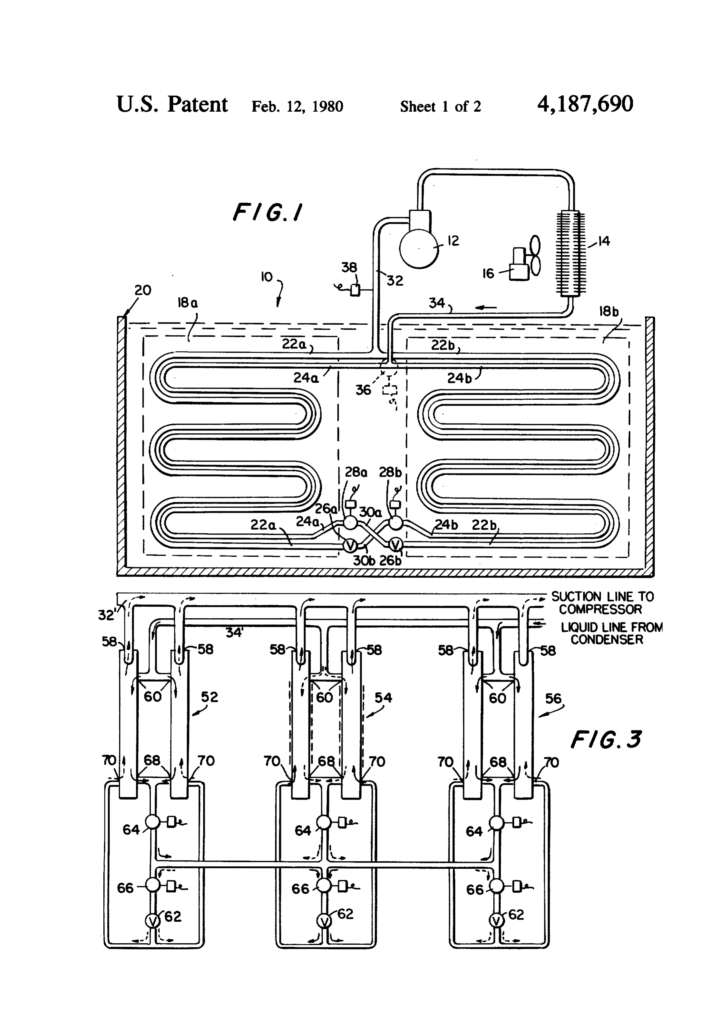
the liquid, after it leaves the heated freezing plates, FIG, 1 is a schematic representation of an embodi through an expansion device and into another evapora 45 ment of the present invention;
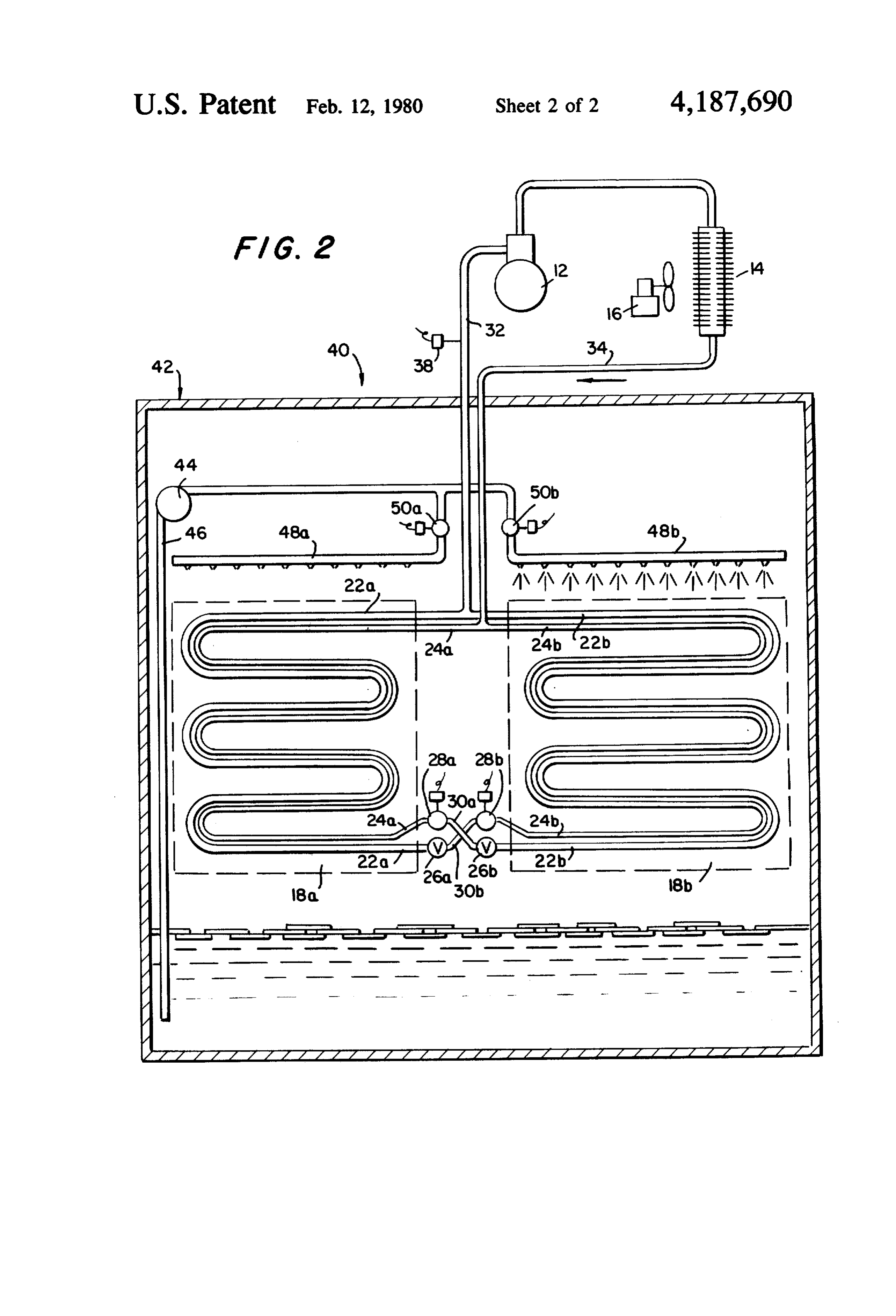
tor freezing plate which is then cooled by the boiling FIG. 2 is a schematic representation of a second em refrigerant. Such an arrangement is disclosed in U.S. bodiment of the present invention; and
Pat. No. 3,537,274 to Tilney. However, a four-way fluid FIG. 3 is a schematic representation of a third em valve is required, in addition to a separate set of check bodiment of the present invention.
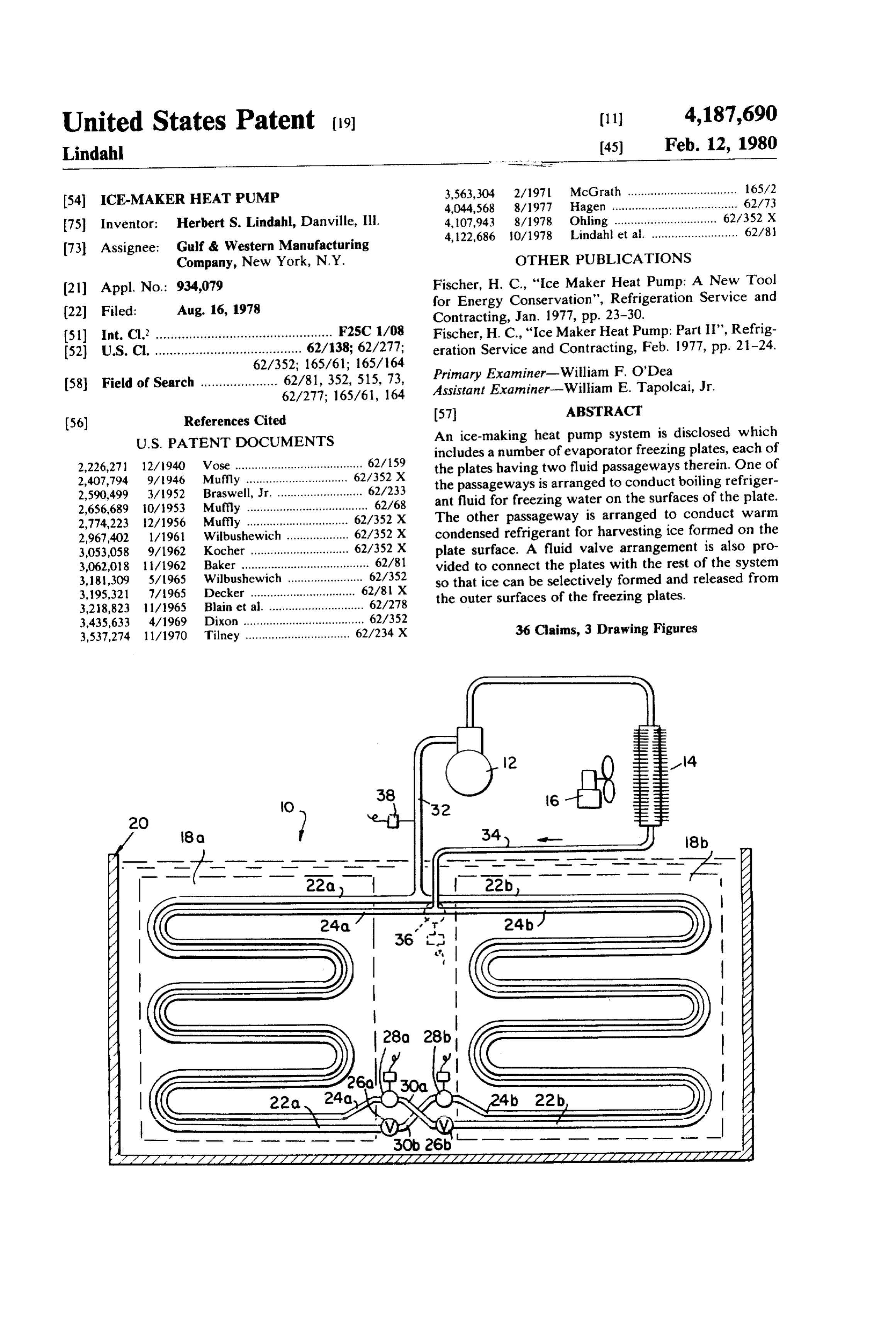
valves should the expansion devices themselves not 50 Referring now in detail to the drawings and particu block reverse flow of refrigerant. Accordingly, use of larly to FIG. 1 thereof, there is shown an illustrative common expansion devices such as a capillary tube ice-making heat pump system embodying features of the would therefore necessitate several different fluid present invention, generally designated by the reference valves, and the overall reliability of a system as dis numeral 10.
closed in the Tilney patent would suffer. 55 Basically, the system includes a compressor 12, a Evaporators including a separate conduit for passing condenser 14 which, for example, may be arranged in warm refrigerant therethrough to defrost the evapora heat exchange relationship with respect to a space to be tor are also known, examples appearing in U.S. Pat. heated within a building by way of a circulating fan 16, Nos. 3, 195,321 to Decker, et al.; and 3,218,823 To Blain, and an evaporator including a pair of evaporator freez et al. In order to prevent liquid refrigerant from return 60 ing plates 18a and 18b, respectively. The compressor 12, ing to the compressor, both Decker and Blain provide condenser 14 and fan 16 may all be conventional units, separate means for boiling the liquid before returning it their size and operating parameters being dictated only to the compressor, i.e., evaporation by hot compressed by the desired capabilities of the system 10. gas in Decker, and expansion by a capillary in Blain. In the embodiment shown in FIG. 1, evaporator However, there is no suggestion in either Decker or 65 plates 18a, 18b are submerged in water contained in a Blain of arranging a number of the evaporators dis tank 20. The plates 18a, 18b should be a sufficient dis closed therein for selective ice-making and harvesting tance below the top surface of the water in order that operations. ice formed on and later released from either of the
Page 5
plates 8a, 18b can float toward the top of the water to a predetermined thickness of ice which accumulates without accumulating to a depth which would interfere on the freezing plates. The device 38 is coupled to the with the further release of ice from either of plates 18a, valves by way of an unshown conventional alternating 18b. The relative size of the freezing plates 18a, 18b switch and voltage source.
with respect to the tank 20 need not be as large as that It will further be appreciated that conventional cold suggested in FIG. 1, the representation therein of plates water circulating means (unshown in FIG. 1) including 18a, 18b being only schematically shown. a pump and a heat exchanger may be arranged in combi Each of the freezing plates 18a, 18h includes cooling nation with the system 10. A cold water pickup line can passageways 22a, 22b, extending respectively there extend below the surface of the water in the tank 20, and through. Passageways 22a, 22b are preferably in the 10 the water may then be drawn up to be pumped and form of copper tubing and are arranged to conduct circulated in heat exchange relationship with a space to relatively cold, boiling refrigerant in heat exchange be cooled within a building. A separate return line, relationship with the water in the tank 20. These cool opening above the tank 20, would also be provided for ing passageways have inlet ends which are shown at the returning the circulated water to the tank. Accordingly, bottoms of the plates 18a, 18b in FIG. 1, and have outlet 15 the system 10 of FIG. 1 can provide both heating and ends which appear toward the tops of the plates. cooling functions.
Each of the plates 18a, 18b also includes heating pas In operation, as described earlier, the present ice sageways 24a, 24b, extending respectively there making heat pump system 10 causes ice to be formed on through, the passageways 24a, 24b also preferably one of the evaporator plates 18a, 18b while the other formed of copper tubing and arranged to conduct rela plate harvests ice previously formed thereon. Heat ex tively warm liquid refrigerant in heat exchange relation tracted from the water in the tank 20 is recovered by ship with ice formed on the outer surfaces of the plates way of the compressor 12 and condenser 14, and can 18a, 18b, respectively. Inlet ends of the heating passage then be used with the assistance ways are shown toward the tops of the plates, and their 16, for example, to distribute ofthetherecoveredcirculating fan outlet ends are toward the bottoms of plates 18a, 18b in 25 throughout a space to be heated in a building. Onceheat ice FIG 1.
Coupled to the inlet end of each of the cooling pas at formed on one of the plates 18a, 18b reaches a thickness sageways 22a, 22b, as shown toward the bottom of FIG. through which the heat recovered by refrigerant flowing 1, are expansion devices 26a, 26b, respectively. These about inch the plate starts to significantly decrease, e.g., devices are preferably in the form of conventional ex while the other (0.64 cm.), ice is harvested from that plate pansion valves or capillary tubes. Also, conventional vesting ice, is brought plate, which has previously been har solenoid valves 28a, 28b are each coupled at one end to into an ice-making mode of oper the outlet end of heating passageways 24a, 24b, respec ation.
tively, as shown toward the bottom of FIG. 1. Solenoid For purposes of the following description, it will be valve 28a is connected at its other end to the expansion 35 assumed that solenoid valves 28a, 28b are incorporated device 26b by way of conduit 30a. Similarly, solenoid in the system 10, and that a direct T-fitting connection valve 28b is connected at its other end to the expansion is provided between the heating passageways 24a, 24b device 26a by a separate conduit 30b. and the condenser 14. Also, it will be assumed that the The outlet ends of each of the cooling passageways system is in a condition such that solenoid valve 28a is 22a, 22b are joined together as by a T-fitting, as shown open and solenoid valve 28b is closed. toward the top of FIG. , which communicates vapor Relatively warm refrigerant leaves the compressor 12 refrigerant in both of the passageways 22a, 22b back in vapor form at high pressure and enters condenser 14 toward the compressor 12 by way of a suction return whereat the high pressure refrigerant vapor condenses line 32. Also, the inlet ends of both the heating passage and heat is released therefrom. The released heat is ways 24a, 24b are joined together as by another T-fit 45 directed by fan 16 to an area to be heated. ting which communicates relatively warm liquid refrig The condensed refrigerant continues through liquid erant from the condenser 14 through liquid line 34 to flow line 34 to the T-connection provided between the both of the heating passageways 24a, 24b, heating passageways 24a, 24b and down through these Alternatively, the solenoid valves 28a, 28b can be passageways to the solenoid valves 28a, 28b. Since eliminated, and direct connections provided between SO valve 28b is closed, the condensed refrigerant is pre the outlet ends of heating passageways 24a, 24b and the vented from moving therepast and remains stationary expansion devices 26b, 26a, respectively. In such a case, within heating passageway 24b.
single three-way valve 36, shown dotted in FIG. 1, The solenoid valve 28a being open, condensed refrig replaces the T-fitting connection otherwise provided erant flows therepast from the heating passageway 24a between the inlet ends of the heating passageways 24a, 55 and into the expansion device 26b associated with cool 24b. Valve 36 may be conventional and should be of a ing passageway 22b. The flow of condensed refrigerant type which, upon actuation, communicates warm re through heating passageway 24a thereby allows heat to be transferred from the refrigerant to the freezing plate frigerant in liquid line 34 to a selected one of the heating passageways 24a and 24b. 18a so as to harvest ice previously formed on the sur In order that the ice-making and ice-harvesting oper 60 face of freezing plate 18a. As the condensed liquid re ations of each of the freezing plates 18a, 18b may be frigerant passing through valve 28a is under high pres automatically controlled, an actuating device 38 can be Sure, its passage through the expansion device 26b sub coupled to the suction return line 32 to selectively actu stantially reduces the pressure thereof, thereby allowing ate the solenoid valves 28a, 28b, or the three-way valve it to evaporate as it flows within the cooling passage 36, and thereby control the flow of both expanded and 65 way 22b of freezing plate 18b. The boiling refrigerant warm refrigerant through the passageways in each of then flows through passageway 22b, and the cooling the freezing plates 18a, 18b. Actuating device 38 may be effect thereof freezes water present on the outer surface a conventional temperature sensor set to be responsive of the freezing plate 18b. The vapor, after leaving the
Page 6
outlet of passageway 22b, is returned to compressor 12 remains stationary owing to the position of the valve 36, by way of suction line 32. and therefore does not prevent the cooling of freezing As ice continues to form on freezing plate 18b, it has plate 18a by evaporating refrigerant in passageway 22a. been found that the ability of the boiling refrigerant to Once ice formed on the surface of freezing plate 18a remove heat from the surrounding water starts to di 5 reaches the predetermined thickness, actuating device minish significantly once the ice reaches a thickness of 38 again responds to cause the three-way valve 36 to about to inch (0.64 to 1.27 cm.) on the freezing plate return to its prior position and the operational modes of surface. After ice is formed on freezing plate 18b to a freezing plates 18a, 18b are again interchanged. predetermined thickness in the above range, actuating A second embodiment of the present invention is device 38 senses a corresponding suction temperature 10 shown in FIG. 2. This embodiment, designated gener drop and causes solenoid valve 28a to close and sole ally by reference numeral 40, includes a water storage noid valve 28b to open. Additional refrigerant is pre tank 42 for containing a quantity of water above which vented from entering the cooling passageway 22b. Rela the freezing plates 18a and 18b are suspended. In order tively warm, condensed refrigerant including the refrig to bring water in the tank 42 into contact with the outer erant previously stationary in passageway 24b is permit 15 surfaces of the freezing plates 18a, 18th, a water-circulat ted to circulate in passageway 24b to harvest ice from ing pump 44 is disposed in tank 42 above the water the surface of freezing plate 18b. This refrigerant passes level, and operates to pump the water through a conduit through valve 28b and expansion device 26a into the 46 and into a pair of spray heads 48a, 48b mounted cooling passageway 22a where it boils so as to freeze above and over each of the freezing plates 18a, 18b, water in contact with the surface of freezing plate 18a. 20 respectively. Associated with each of the spray heads Vapor refrigerant leaving the outlet of passageway 22a 48a, 48b are solenoid shutoff valves 50a, 50 b, respec is then returned to the compressor 12 by way of the tively.
suction line 32. It will be appreciated that stationary Apart from the relative positioning of the freezing condensed refrigerant in passageway 24a will not pre plates 18a, 18b with respect to the water in tank 42, vent ice from being formed on freezing plate 18a, its 25 ice-making heat pump system 40 in FIG. 2 is in other movement being prevented by the closed solenoid respects similar to the system 10 of FIG. 1. It will be valve 28a. appreciated, however, that harvesting of ice from the Because of the above-described construction and freezing plates 18a, 18b can be facilitated by keeping the arrangement of the ice-making heat pump system 10, freezing plate outer surfaces free of chilled water during those skilled in the art will appreciate that ice-making 30 the harvesting mode of operation of each of the plates. and harvesting is selectively performed by evaporator Accordingly, the water spray from the spray heads 48a, freezing plates 18a, 18b without introducing hot gas or 48b onto the freezing plates 18a, 18b is controlled by warm liquid refrigerant into the cooling passageways valves 50a, 50b so that water is sprayed only on the 22a, 22b of the plates. Accordingly, successful opera plate which is being cooled by refrigerant. The valves tion and long life of the compressor 12 is assured in that 35 50a, 50b are selectively energized by way of the actuat liquid is not accumulated in the cooling passageways ing device 38 in the same manner by which the device 22a, 22b to be returned to the compressor 12 as in some 38 actuates the refrigerant shutoff valves 28a, 28b, as of the above prior systems. explained in regard to the embodiment of FIG. 1. In the event it is desired to use the single three-way It will be appreciated that when refrigerant shutoff valve 36 instead of the solenoid valves 28a, 28b, the 40 valve 28a is opened to allow refrigerant to boil within operation of the system 10 remains much the same as freezing plate 18b to freeze water on the surface thereof, described above. Assuming that the valve 36 is set to valve 50b is also opened to permit the spray head 48b to allow the condensed liquid refrigerant leaving con spray freezing plate 18b with water, as shown in FIG. 2. denser 14 through line 34 to enter heating passageway Conversely, when freezing plate 18a is in the ice-mak 24a, the relatively warm refrigerant will cause ice previ 45 ing mode wherein refrigerant valve 28b is opened to ously formed on freezing plate 18a to be harvested. The permit refrigerant to boil within the plate 18a, then refrigerant leaves passageway 24a and directly enters valve 50a is opened to spray water down upon freezing expansion device 26b, thereby evaporating within the plate 18a, thereby enabling ice to form on the surface of cooling passageway 22b to cause water in contact with plate 18a, the surface of freezing plate 18b to become frozen. The SO Although not shown in FIG. 2, the system 40 can also vapor refrigerant leaves the outlet of passageway 22b to operate with the single three-way valve 36 as in the enter suction line 32, and returns to compressor 12. embodiment of FIG. 1, the two refrigerant shutoff When a predetermined thickness of ice is formed on the valves 28a, 28b then being bypassed. surface of freezing plate 18b, actuating device 38 re Also, a separate cold water circulating system (un sponds to cause valve 36 to change its position and 55 shown in FIG. 2) can be arranged to circulate chilled redirect the flow of warm condensed refrigerant water in the tank 42 through a heat exchanger in a through the heating passageway 24b of freezing plate building to provide cooling, as described above in con 18b and into the expansion device 26a associated with nection with the embodiment of FIG. 1. freezing plate 18a. This movement of the condensed Thus far, the present invention has been described as refrigerant causes ice formed on the surface of freezing 60 including a single pair of freezing plates 18a, 18b, one of plate 18b to be harvested. which forms ice on its surface while the other harvests As the refrigerant flows past expansion device 26a, its ice thereon, these operations being interchanged after a pressure is reduced so as to allow it to boil within cool predetermined thickness of ice develops on either of ing passageway 22a and to freeze water on the surface them. It will be understood that any number of pairs of of associated freezing plate 18a. The vapor refrigerant 65 freezing plates, each pair being interconnected as leaves the outlet of passageway 22a for return to com shown in FIG. 1 or 2, may all be connected in parallel pressor 12 by way of suction line 32. It will be under with compressor and condenser units of suitable size to stood that condensed refrigerant within passageway 24a thereby increase the heating and cooling capacity of the
Page 7
entire system. Accordingly, the present invention is not by the dotted arrows in FIG. 3, condensed refrigerant is limited to a single pair of freezing plates as shown in permitted to flow through the heating passageways in FIGS. 1 and 2. plate pair 54 at inlets 60 so as to heat and release ice FIG. 3 represents a third embodiment of the present formed on the surfaces of these plates. The refrigerant invention in which a number of sets of freezing plates leaves the plates 54 at outlets 68 and flows past the (three pairs being illustrated) are arranged so that both associated valve 64 which is now in an open position. plates in a given pair either form or harvest ice together valve 66 associated with the plate pair 54 now being at a particular time. It will be understood that any num closed, the liquid refrigerant moves toward the valves ber of freezing plate sets may be used, with two or more associated with the outer freezing plate pairs 52 and 56. freezing plates in each set, provided a compressor and O The refrigerant then passes through associated valves condenser of suitable capacity are employed. For con 66 and expansion devices 62. Boiling refrigerant then venience in the following description, the three illus enters the cooling passageways of outer plate pairs 52 trated pairs of freezing plates are designated by numer and 56, at 70, and boils through these cooling passage als 52, 54 and 56, respectively. ways to form ice on the outer surfaces of the respective Each of the evaporator plates includes separate cool 15 plates. The vapor refrigerant leaves the cooling pas ing and heating passageways (unshown) as do the evap sageways at outlets 58 to return to the compressor by orator plates 18a and 18b in the embodiments of FIGS. way of the suction line 32".
1 and 2. The cooling passageways of the evaporator The particular freezing plate arrangement shown in plates in FIG. 3 have their outlet ends at 58 connected FIG. 3 can be adapted for use in a system such as shown with the suction line 32 leading to the low pressure side in FIG. 1, wherein the freezing plates are submerged in of an unshown compressor. Also, the inlet ends of the water, or in a system as shown in FIG. 2, wherein the heating passageways are connected at 60 to the con freezing plates are suspended above water and a spray denser liquid line 34. or shower of water is selectively directed on those The evaporator plate pairs 52, 54 and 56 are intercon freezing plates in an ice-making mode of operation. nected by a valve arrangement as shown in the lower 25 A latitude of variation, modification, change and half of FIG. 3, including a set of expansion devices 62 substitution is intended in the foregoing disclosure. For associated with each of the freezing plate pairs. In this example, instead of providing the actuating device 38 embodiment, freezing plate pair 54 can be selected for for switching the valves associated with the freezing the ice-forming mode of operation while the remaining plates herein disclosed, other devices directly respon two pairs 52, 56 operate to harvest ice previously sive to the build-up of a predetermined thickness of ice formed thereon. Alternatively, plate pair 54 is caused to may be located on the freezing plates themselves, or a harvest the ice formed thereon while the other two conventional timing device can be used to periodically pairs 52, 56 form ice on their surfaces. The former mode switch the operational modes of the plates. Also, al of operation is depicted by solid arrows representing though water is a preferred liquid to be used for trans refrigerant flow, and the dotted arrows represent flow ferring heat contained therein to refrigerant within the of refrigerant during the latter mode of operation. present freezing plates, other liquids may be used as The valve arrangement in the system of FIG. 3 in would be well-known to those skilled in the art. There cludes a set of refrigerant shutoff solenoid valves 64, 66 fore, it is appropriate that the appended claims be con for each evaporator plate pair, and operates to direct strued broadly and in a manner consistent with the spirit the flow of warm condensed refrigerant leaving the 40 and scope of the invention.
heating passageways of one pair of evaporator plates What is claimed is:
through an expansion device 62 and into the cooling 1. An improved evaporator for an ice-making heat passageways of another evaporator plate pair. For ex pump of the type which includes a compressor for cir ample, solid arrows are used to illustrate the refrigerant culating a supply of refrigerant, a condenser, and an flow through the system of FIG. 3 at a time when the 45 evaporator, said evaporator adapted to be arranged in middle evaporator plate pair 54 is forming ice, and the heat exchange relationship with water to be in contact outer plate pairs 52 and 56 are harvesting ice. therewith and comprising a plurality of freezing plates, As seen in FIG. 3, condensed, relatively warm liquid each of said freezing plates having a first passageway refrigerant enters the heating passageways at 60 in plate therein arranged to conduct relatively cold evaporating pairs 52 and 56, and heats these plates to release ice SO refrigerant therethrough in heat exchange relationship formed on their outer surfaces. The liquid refrigerant with water to be in contact with the outer surfaces of moves out from the heating passageways at 68 and past said freezing plates to form ice on the outer surface of at shutoff valves 64 which are considered to be open. The least one of said freezing plates, and a second passage refrigerant then flows toward the plate pair 54, past way therein arranged to conduct relatively warm re shutoff valve 66 associated therewith and also presumed frigerant therethrough in heat exchange relationship to be open, and through the expansion device 62 associ with the ice to be formed on the outer surface of at least ated with freezing plate pair 54. Boiling refrigerant then one of said freezing plates to release said ice, each of enters into inlets 70 of the cooling passageways in plate said passageways having inlet and outlet ends, respec pair 54, thereby freezing water present on the outer tively, and valve means coupled between said freezing surfaces of plate pair 54. The vapor refrigerant contin 60 plates arranged to selectively direct said refrigerant ues to move through outlets 58 of the cooling passage between said first and second passageways in each of ways and is returned to the compressor by way of suc said freezing plates to enable said ice to be selectively tion line 32". formed on and released from the outer surfaces of said After the build-up of a predetermined thickness of ice freezing plates when said evaporator is operatively on freezing plate pair 54, all the shutoff valves 64 and 66 5 connected to said heat pump. are switched so as to redirect the flow of warm liquid 2. An evaporator according to claim 1 further includ refrigerant through freezing plate pair 54, rather than ing means for reducing the pressure of the refrigerant through plate pairs 52 and 56. Accordingly, as shown coupled between the outlet end of the second passage
Page 8
9 O way of one of said freezing plates and the inlet end of including a plurality of freezing plates each having a the first passageway in another of said freezing plates. first passageway therein arranged to conduct relatively 3. An evaporator according to claim 2, wherein said cold evaporating refrigerant therethrough in heat ex pressure reducing means comprises an expansion valve. change relationship with said supply of water to form 4. An evaporator according to claim 2, wherein said ice on the outer surface of at least one of said freezing pressure reducing means comprises a capillary tube. plates, and a second passageway therein arranged to 5. An evaporator according to claim 1, wherein said conduct relatively warm refrigerant therethrough in valve means comprises a fluid valve and further in heat exchange relationship with the ice to be formed on cludes means for actuating said fluid valve in response the outer surface of at least one of said freezing plates to to ice formed on at least one of said freezing plates. 10 release said ice, each of said passageways having inlet 6. An evaporator according to claim 5, wherein said and outlet ends, respectively, and valve means coupled actuating means actuates said fluid valve in response to between said freezing plates arranged to selectively a predetermined thickness of ice. direct said refrigerant between said first and second 7. An ice-making heat pump system comprising a passageways in each of said freezing plates to enable compressor for circulating a supply of refrigerant 5 said ice to be selectively formed on and released from through said system, a condenser arranged in heat ex the outer surfaces of said freezing plates. change relationship with said refrigerant for removing 15. A heat pump system according to claim 14, fur heat from said refrigerant, and evaporator coupled to ther including means communicating with said tank for said compressor and arranged in heat exchange relation circulating said supply of water in heat exchange rela ship with water to be in contact therewith, said evapo 20 tionship with a space to be cooled. rator including a plurality of freezing plates each having 16. A heat pump system according to claim 14, fur a first passageway therein arranged to conduct rela ther including means for reducing the pressure of the tively cold evaporating refrigerant therethrough in heat refrigerant coupled between the outlet end of the sec exchange relationship with water to be in contact with ond passageway of one of said freezing plates and the the outer surfaces of said freezing plates to form said ice 25 inlet end of the first passageway in another of said freez on the outer surface of at least one of said freezing ing plates.
plates, and a second passageway therein arranged to 17. A heat pump system according to claim 16, conduct relatively warm refrigerant therethrough in wherein said pressure reducing means comprises an heat exchange relationship with the ice to be formed on expansion valve.
the outer surface of at least one of said freezing plates to 30 18. A heat pump system according to claim 16, release said ice, each of said passageways having inlet wherein said pressure reducing means comprises a cap and outlet ends, respectively, and valve means coupled illary tube.
between said freezing plates arranged to selectively 19. A heat pump system according to claim 14, direct said refrigerant between said first and second wherein said valve means comprises a fluid valve and passageways in each of said freezing plates to enable 35 further includes means for actuating said fluid valve in said ice to be selectively formed on and released from response to ice formed on at least one of said freezing the outer surfaces of said freezing plates. plates.
8. A heat pump system according to claim 7, further 20. A heat pump system according to claim 19, including means for circulating said water in heat ex wherein said actuating means actuates said fluid valve in change relationship with a space to be cooled. response to a predetermined thickness of ice. 9. A heat pump system according to claim 7, further 21. An ice-making heat pump system comprising a including means for reducing the pressure of the refrig compressor for circulating a supply of refrigerant erant coupled between the outlet end of the second through said system, a condenser arranged in heat ex passageway of one of said freezing plates and the inlet change relationship with said refrigerant for removing end of the first passageway in another of said freezing 45 heat from said refrigerant, a tank for containing a supply plates. of water, an evaporator coupled to said compressor and 10. A heat pump system according to claim 9, said condenser, said evaporator being arranged substan wherein said pressure reducing means comprises an tially above said supply of water, means communicating expansion valve. with said supply of water for spraying said water onto 11. A heat pump system according to claim 9, 50 said evaporator, said evaporator including a piurality of wherein said pressure reducing means comprises a cap freezing plates each having a first passageway therein illary tube. arranged to conduct relatively cold evaporating refrig 12. A heat pump system according to claim 7, erant therethrough in heat exchange relationship with wherein said valve means comprises a fluid valve and water to be sprayed on the outer surfaces of said freez further includes means for actuating said fluid valve in 55 ing plates to form ice on the outer surface of at least one response to ice formed on at least one of said freezing of said freezing plates, and a second passageway therein plates. arranged to conduct relatively warm refrigerant there 13. A heat pump system according to claim 12, through in heat exchange relationship with the ice to be wherein said actuating means actuates said fluid valve in formed on the surface of at least one of said freezing response to a predetermined thickness of ice. plates to release said ice, each of said passageways hav 14. An ice-making heat pump system comprising a ing inlet and outlet ends, respectively, and valve means compressor for circulating a supply of refrigerant coupled between said freezing plates arranged to selec through said system, a condenser arranged in heat ex tively direct said refrigerant between said first and sec change relationship with said refrigerant for removing ond passageways in each of said freezing plates to en heat from said refrigerant, a tank for containing a supply 65 able said ice to be selectively formed on and released of water, and an evaporator coupled to said compressor from the outer surfaces of said freezing plates. and said condenser, said evaporator being arranged to 22. A heat pump system according to claim 21, fur be substantially submerged in said supply of water and ther including means communicating with said tank for
Page 9
circulating said supply of water in heat exchange rela evaporating refrigerant therethrough in heat exchange tionship with a space to be cooled. relationship with water to be in contact with the outer 23. A heat pump system according to claim 21, fur surfaces of said freezing plates to form ice thereon, and ther including means for reducing the pressure of the a second passageway therein arranged to conduct rela refrigerant coupled between the outlet end of the sec tively warm refrigerant therethrough in heat exchange ond passageway of one of said freezing plates and the relationship with said ice to release said ice, the first and inlet end of the first passageway in another of said freez second passageways of the freezing plates in each said ing plates. freezing plate set having inlet and outlet ends and being 24. A heat pump system according to claim 23, arranged in parallel with each other, and valve means wherein said pressure reducing means comprises an 10 coupled between each of said sets of freezing plates expansion valve. arranged to selectively direct said refrigerant between 25. A heat pump system according to claim 23, said first and second parallel passageways in each of wherein said pressure reducing means comprises a cap said sets of freezing plates to enable said ice to be selec illary tube.
tively 26. A heat pump system according to claim 21, 15 each said freezingformed on and released from the outer surfaces of wherein said valve means comprises a fluid valve and plate set. further includes means for actuating said fluid valve in ther including meanssystem 31. A heat pump according to claim 30, fur response to ice formed on at least one of said freezing exchange relationship with a space tosaid for circulating water in heat be cooled.
plates.
27. A heat pump system according to claim 26, 20 32. A heat pump system according to claim 30, fur wherein said actuating means actuates said fluid valve in ther including means for reducing the pressure of the response to a predetermined thickness of ice. refrigerant coupled between the outlet ends of the sec 28. A heat pump system according to claim 21, ond passageways of one of said freezing plate sets and wherein said spray means includes means for selectively the inlet ends of the first passageways in another of said spraying said water onto said freezing plates. 25 freezing plate sets.
29. A heat pump system according to claim 28, 33. A heat pump according to claim 32, wherein said wherein said selective spraying means includes means pressure reducing means comprises an expansion valve. responsive to ice formed on at least one of said freezing 34. A heat pump system according to claim 32, plates. wherein said pressure reducing means comprises a cap 30. An ice-making heat pump system comprising a 30 illary tube, compressor for circulating a supply of refrigerant 35. A heat pump system according to claim 30, through said system, a condenser arranged in heat ex wherein said valve means comprises a fluid valve and change relationship with said refrigerant for removing further includes means for actuating said fluid valve in heat from said refrigerant, an evaporator coupled to response to ice formed on at least one of said freezing said compressor and arranged in heat exchange relation 35 plate sets.
ship with water to be in contact therewith, said evapo 36. A heat pump according to claim 35, wherein said rator including a plurality of freezing plates arranged in actuating means actuates said fluid valve in response to respective sets, each of said freezing plates having a first a predetermined thickness of ice. passageway therein arranged to conduct relatively cold k k sk
Provenance
- Collection
- Cited prior art
- Original PDF
- patentimages.storage.googleapis.com →
- Filed
- 1978-08-16
- Pages
- 9
- Method
- pdftotext (the PDF's own text layer) + pdftoppm 300dpi page scans
- Source
- Google Patents bibliographic record
- Granted
- 1980-02-12
- Inventors
- Herbert S. Lindahl; Gulf and Western Manufacturing Co
- Transcribed from
- patentimages.storage.googleapis.com →