patent · US3467812
Igniter-thermistor assembly
16 September 1969
Page 1 — bibliographic record
Sept. 16, 1969 w. T, TERRELL 3,467,812
IGNITER-THERMISTOR ASSEMBLY
Filed March 29, 1967 2 Sheets-Sheet
6' 4' 44 34 19 2' 20 8' 5%NA 4 V4 V4 44 4 3/?? is 4ONSPEGata ada
42 8.- : ... AVOXVAVAV . N
ŽZZZZZZNZNZNZN 36' 4
INVENTOR.
WLLAM T. TERRELL
Page 2
Drawing sheet — no readable text.
Page 3
United States Patent Office 3,467,812 Patented Sept. 16, 1969
become more apparent upon consideration of the follow 3,467,812 ing detailed description thereof when taken in conjunction GNTERTHERMISTOR ASSEMBLY with the following drawings, in which:
William T. Terrell, Youngstown, N.Y., assignor to The FIG. 1 is a perspective view of the igniter-thermistor Carborundum Company, Niagara Falls, N.Y., a cor assembly constructed in accordance with the principles poration of Delaware of this invention;
Filed Mar. 29, 1967, Ser. No. 626,745 FIG. 2 is a longitudinal section of the igniter-ther Int. Cl. F23q 7/00 mistor assembly shown in FIG. 1;
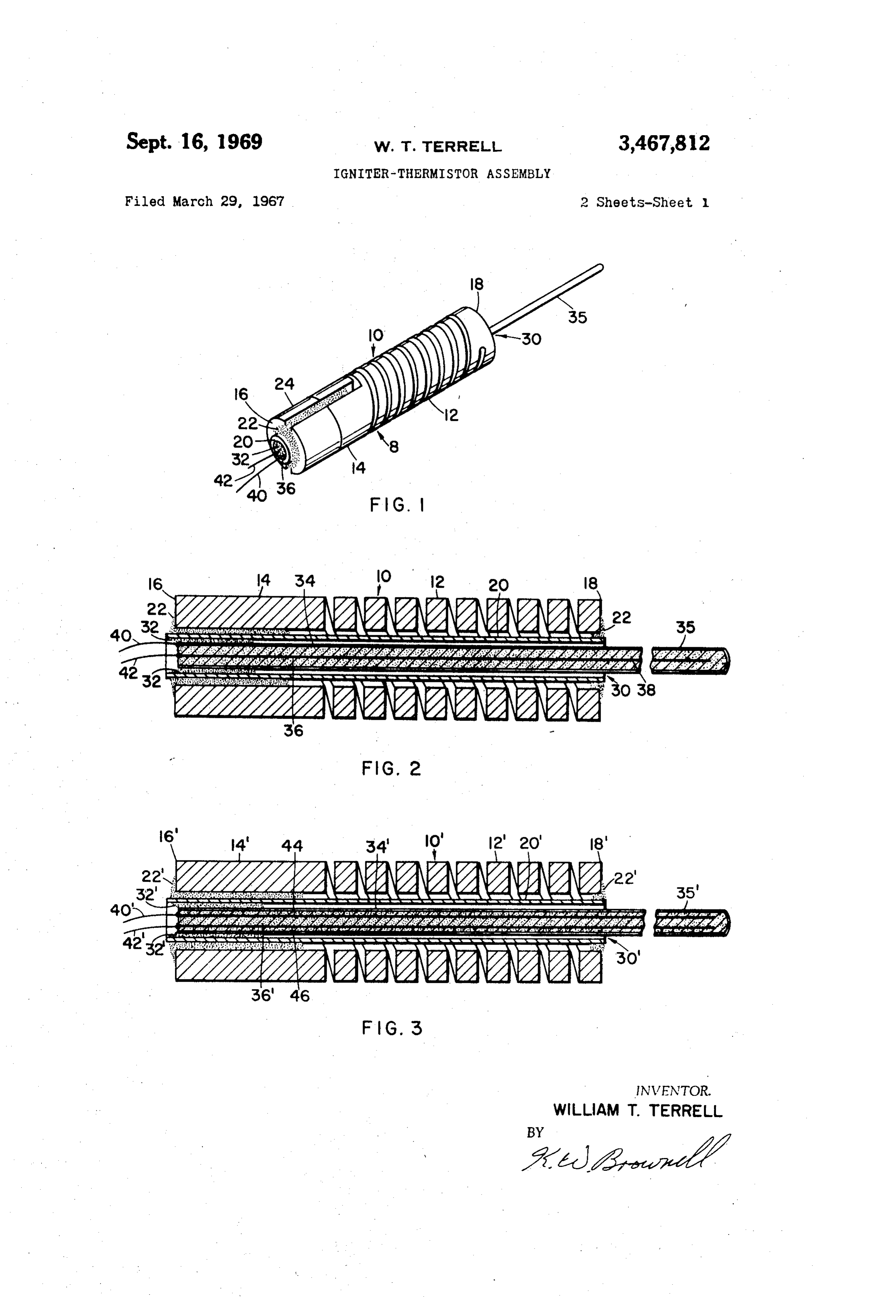
FIG. 3 is a view similar to FIG. 2 illustrating a second 10 embodiment of the igniter-thermistor assembly of this
ABSTRACT OF THE DISCLOSURE invention;
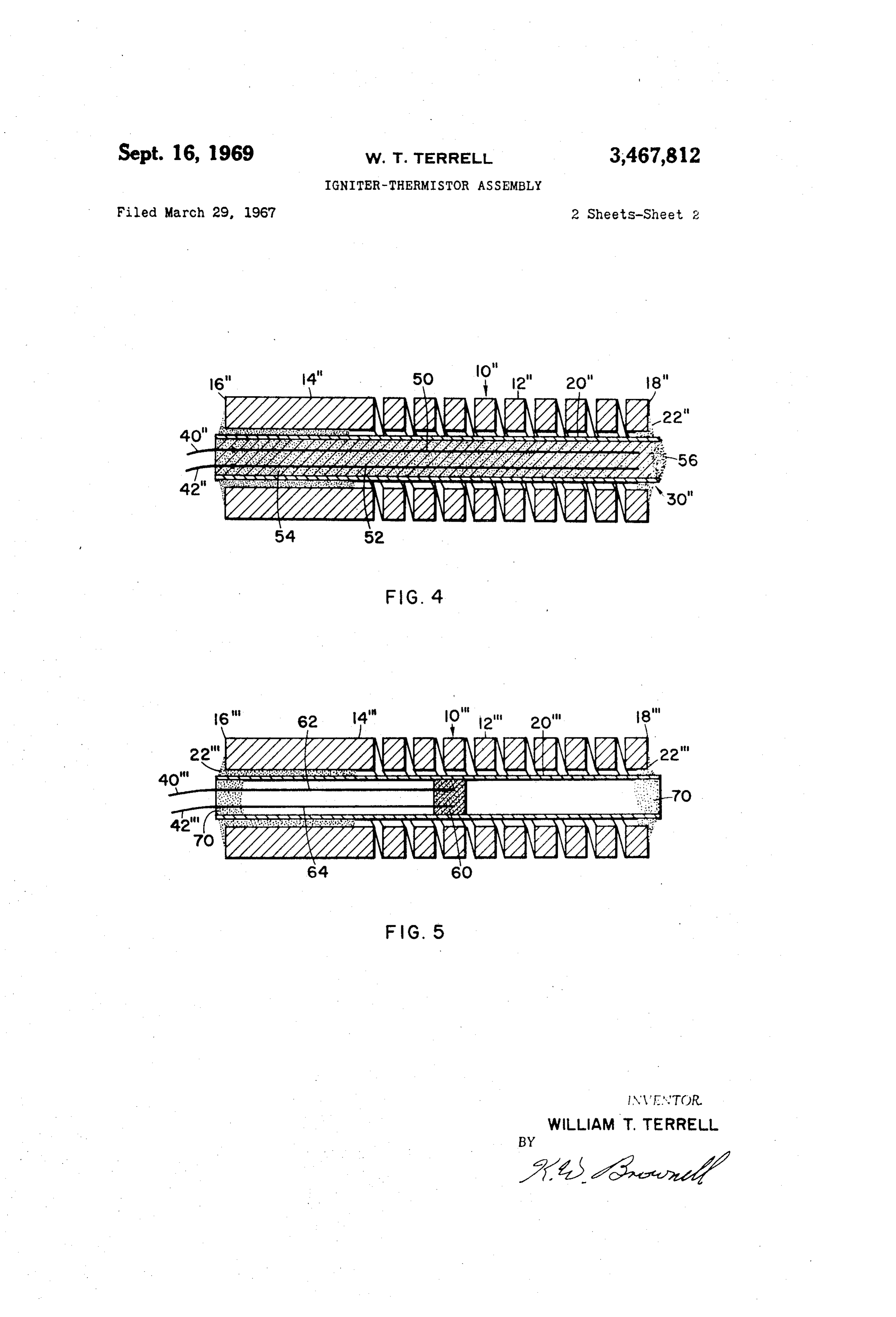
An igniter-thermistor assembly comprising an igniter FIG. 4 is a longitudinal section illustrating a third having a hollow resistance body with a support tube se embodiment of the igniter-thermistor assembly of this invention; and cured therein. A thermistor, having a negative temper 5 FIG. 5 is a longitudinal section of still another embodi ature coefficient, responsive to the igniter when energized ment of the igniter-thermistor assembly of the present is mounted within the support tube. invention.
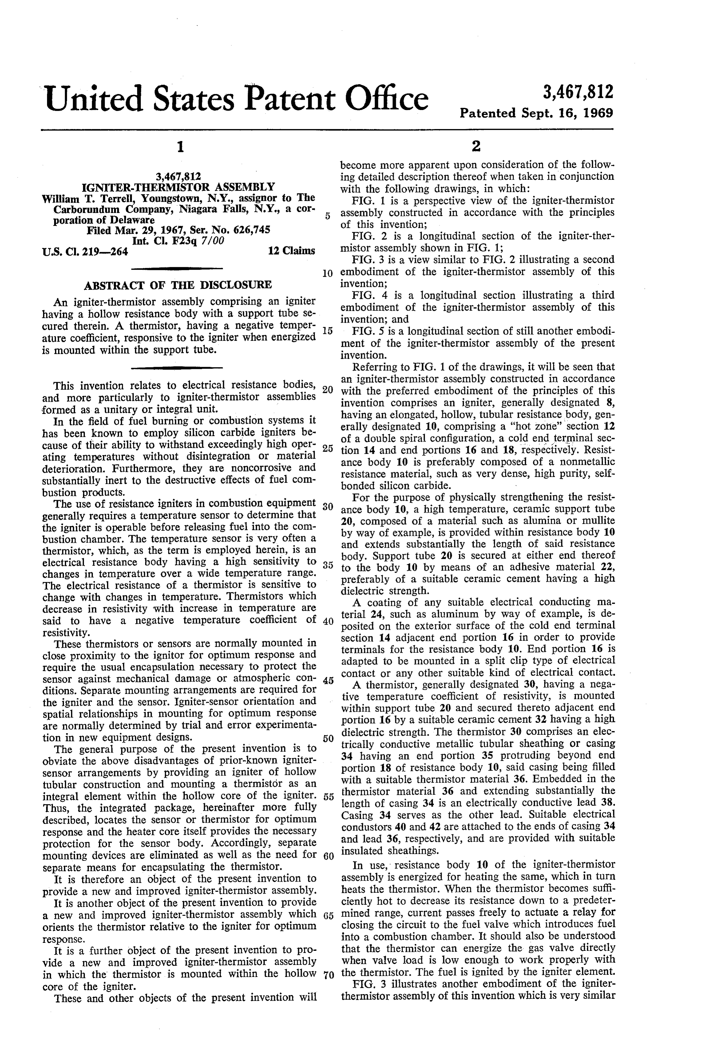
Referring to FIG. 1 of the drawings, it will be seen that
This invention relates to electrical resistance bodies, 20 withigniter-thermistor an assembly constructed in accordance and more particularly to igniter-thermistor assemblies invention comprises an igniter, ofgenerally the preferred embodiment the principles of this designated 8, formed as a unitary or integral unit. having an elongated, hollow, tubular resistance body, gen In the field of fuel burning or combustion systems it erally designated 10, comprising a "hot zone" section 12 has been known to employ silicon carbide igniters be of a double spiral configuration, a cold end terminal sec cause of their ability to withstand exceedingly high oper tion 14 and end portions 16 and 18, respectively. Resist ating temperatures without disintegration or material ance body 10 is preferably composed of a nonmetallic deterioration. Furthermore, they are noncorrosive and resistance material, such as very dense, high purity, self substantially inert to the destructive effects of fuel com bonded silicon carbide.
bustion products. For the purpose of physically strengthening the resist The use of resistance igniters in combustion equipment 30 ance body 10, a high temperature, ceramic support tube generally requires a temperature sensor to determine that 20, composed of a material such as alumina or mullite the igniter is operable before releasing fuel into the com by way of example, is provided within resistance body 10 bustion chamber. The temperature sensor is very often a and extends substantially the length of said resistance thermistor, which, as the term is employed herein, is an body. Support tube 20 is secured at either end thereof electrical resistance body having a high sensitivity to to the body 10 by means of an adhesive material 22, changes in temperature over a wide temperature range. preferably of a suitable ceramic cement having a high The electrical resistance of a thermistor is sensitive to dielectric strength.
change with changes in temperature. Thermistors which A coating of any suitable electrical conducting ma decrease in resistivity with increase in temperature are said to have a negative temperature coefficient of 40 posited24,onsuch terial the as aluminum by way of example, is de exterior surface of the cold end terminal resistivity. section 14 adjacent end portion 16 in order to provide These thermistors or sensors are normally mounted in terminals for the resistance body 10. End portion 16 is close proximity to the ignitor for optimum response and adapted to be mounted in a split clip type of electrical require the usual encapsulation necessary to protect the sensor against mechanical damage or atmospheric con 45 contact or any other suitable kind of electrical contact. A thermistor, generally designated 30, having a nega ditions. Separate mounting arrangements are required for tive temperature coefficient of resistivity, is mounted the igniter and the sensor. Igniter-sensor orientation and within support tube 20 and secured thereto adjacent end spatial relationships in mounting for optimum response portion 16 by a suitable ceramic cement 32 having a high are normally determined by trial and error experimenta tion in new equipment designs. 50 dielectric strength. The thermistor 30 comprises an elec The general purpose of the present invention is to trically conductive metallic tubular sheathing or casing obviate the above disadvantages of prior-known igniter 34 having an end portion 35 protruding beyond end sensor arrangements by providing an igniter of hollow portion 18 of resistance body 10, said casing being filled tubular construction and mounting a thermistor as an with a suitable thermistor material 36. Embedded in the thermistor material 36 and extending substantially the integral element within the hollow core of the igniter. 55 length
Thus, the integrated package, hereinafter more fully of casing 34 is an electrically conductive lead 38. described, locates the sensor or thermistor for optimum Casing 34 serves as the other lead. Suitable electrical response and the heater core itself provides the necessary condustors 40 and 42 are attached to the ends of casing 34 protection for the sensor body. Accordingly, separate and lead 36, respectively, and are provided with suitable mounting devices are eliminated as well as the need for 60 insulated sheathings.
separate means for encapsulating the thermistor. In use, resistance body 10 of the igniter-thermistor It is therefore an object of the present invention to assembly is energized for heating the same, which in turn provide a new and improved igniter-thermistor assembly. heats the thermistor. When the thermistor becomes suffi It is another object of the present invention to provide ciently hot to decrease its resistance down to a predeter a new and improved igniter-thermistor assembly which 65 mined range, current passes freely to actuate a relay for orients the thermistor relative to the igniter for optimum closing the circuit to the fuel valve which introduces fuel response. into a combustion chamber. It should also be understood It is a further object of the present invention to pro that the thermistor can energize the gas valve directly vide a new and improved igniter-thermistor assembly when valve load is low enough to work properly with in which the thermistor is mounted within the hollow 70 the thermistor. The fuel is ignited by the igniter element. core of the igniter. FIG. 3 illustrates another embodiment of the igniter These and other objects of the present invention will thermistor assembly of this invention which is very similar
Page 4
to the above-described embodiment with the exception trical conducting material forming terminals thereon; a that rather than employing the casing as one electrical support tube suitably secured within said resistance body; conductive lead, two separate leads are contained within means for electrically insulating said tube from said re the casing. All of the other structural features and their sistance body; a thermistor mounted within said support resultant functions are duplicated in the embodiment of 5 tube; a pair of electrical leads connected to said therm FIG. 3 and the same reference characters primed are used istor; and means for electrically insulating said therm to identify elements which are similar to those used in the istor from said tube.
first embodiment. As shown in FIG. 3, electrical conduc 2. An igniter-thermistor assembly as defined in claim tive leads 44 and 46 are embedded in a suitable thermistor 1 in which said thermistor has a negative temperature co material 36 contained within casing 34. An advantage 10 efficient and includes a thermistor material and in which residing in this second embodiment over the first is that at least a portion of one of said pair of leads is embedded the casing 34 per se is at zero electrical potential when in said thermistor material.
ever the thermistor is cool, thus presenting no electrical 3. An igniter-thermistor assembly as defined in claim shock hazard. The case becomes electrically charged only 2 in which said thermistor is provided with an elongated when the thermistor is exposed to heat. 15 metallic casing enclosing said thermistor material and In both of the above-described embodiments it should having an end portion extending axially beyond said Sup be appreciated that the principles of this invention con port tube and said resistance body.
template the use of thermistors having any desired lengths, 4. An igniter-thermistor assembly as defined in claim i.e. the end of the thermistor may or may not protrude 3 in which said metallic casing serves as one of the elec beyond the end portion 18 of the igniter element, as de 20 trical conductive leads.
sired. 5. An igniter-thermistor assembly as defined in claim A third embodiment of the igniter-thermistor assembly 2 wherein said support tube is secured adjacent the op is shown in FIG. 4. The reference numerals double primed posite ends thereof to said hollow body with a ceramic indicate parts similar to those employed in the first em cement.
bodiment. The igniter-thermistor assembly of FIG. 4 25 6. An igniter-thermistor assembly as defined in claim comprises an igniter having a resistance body 10' and a 2 wherein said hollow body comprises a first portion hav ceramic support tube 20' similar to the resistance body ing a pair of laterally spaced elongated members and a and support tube of the first embodiment described. A pair second portion having a double spiral configuration con of electrical conductive leads 50 and 52 are positioned nected to and extending longitudinally from said elongated within support tube 20' and embedded in a suitable ther members.
mistor material 54 which is packed within support tube 7. An igniter-thermistor assembly as defined in claim 20' and surrounds said conductive leads 50 and 52. A 6 in which the ends of said elongated members remote closure or plug 56, composed of a suitable ceramic cement, from said second portion are coated with an electrical seals off the end of support tube 20'. It will be noted that conducting material and engageable with an electrical a metallic casing is not utilized in this embodiment and 35 contact.
that support tube 20' serves as the casing. Thus, an ad 8. An igniter-thermistor assembly comprising: an vantage residing in this embodiment is that the problem igniter having an elongated hollow resistance body, said of oxidation, which might occur with a metallic shrouded body having outer surface portions coated with an elec thermistor encircled by a heated igniter, is obviated and trical conducting material forming terminals thereon; a the useful life of the igniter-thermistor assembly is pro 40 supporting tube suitably secured within Said resistance longed. body; means for electrically insulating said tube from A fourth embodiment of the igniter-thermistor assembly said resistance body; a thermistor mounted within said is shown in FIG. 5. The reference numerals triple primed tance body; and a pair of electrical leads connected to indicate parts similar to those employed in the first em said thermistor.
bodiment. The ingniter-thermistor asembly of FIG. 5 9. An igniter-thermistor assembly as defined in claim comprises an igniter having a resistance body 10' and 45 8 in which said thermistor has a negative termperature a ceramic support tube 20' similar to the resistance body coefficient and includes a thermistor material and in which and support tube of the first embodiment described. A at least a portion of one of said pair of leads is embedded thermistor element 60, in the form of a pellet, fits snugly in said thermistor material.
within support tube 20' and has a pair of electrical 10. An igniter-thermistor assembly as defined in claim conductive leads 62 and 64 embedded therein and extend 50 9 in which said support tube is ceramic, is provided with ing therefrom. A suitable ceramic cement 70 is provided a plug at one end thereof, and contains said thermistor to seal off both ends of support tube 20'. It will be seen material.
that the cement mix encapsulates portions of leads 62 and 11. An igniter-thermistor assembly as defined in claim 64 and serves to position and secure them in place. 10 in which said thermistor material is in the form of a In all four of the embodiments described above the 55 pellet.
thermistor is of the type having a negative temperature 12. A igniter-thermistor assembly as defined in claim coefficient of resistivity. 11 in which said support tube is provided with a plug at As a result of the present invention, an improved igniter each end thereof and said leads have portions encap thermistor assembly is provided in which a thermistor is sulated and positioned by one of said plugs. mounted within the hollow core of an igniter element for 60 spatially orienting said thermistor relative to the igniter References Cited for optimum thermal response. Moreover, the igniter UNITED STATES PATENTS serves as a shroud to shield the thermistor against atmos pheric conditions and mechanical damage. Also, installa 2,160,823 6/1939 Black -------------- 175-320 tion designs are simplified since less hardware is required 65 2,253,577 8/1941 Pearson et al. --------- 338-23 for mounting the integrated assembly. 2,546,415 3/1951 Alcock -------------- 60-233 Preferred embodiments of this invention having been 2,549,633 4/1951 Ottmar ------------ 431-66 X described and illustrated, it is to be realized that modifica 3,142,479 7/1964 Bartlett et al. ------ 431-66 X tions thereof may be made without departing from the 3,339,164 8/1967 Landis et al. ---------- 338-22 broad spirit and scope of this invention as defined in the 3,372,305 3/1968 Miculec ------------- 317-98 appended claims.
I claim: VOLODYMYR Y. MAYEWSKY, Primary Examiner 1. An igniter-thermistor assembly comprising: an U.S. C. X.R. igniter having an elongated hollow resistance body, said body having outer surface portions coated with an elec 5 123-143; 317-98; 338-22; 340-228
Provenance
- Collection
- Cited prior art
- Original PDF
- patentimages.storage.googleapis.com →
- Filed
- 1967-03-29
- Pages
- 4
- Method
- pdftotext (the PDF's own text layer) + pdftoppm 300dpi page scans
- Source
- Google Patents bibliographic record
- Granted
- 1969-09-16
- Inventors
- William T Terrell; Carborundum Co
- Transcribed from
- patentimages.storage.googleapis.com →