patent · US6079373
Gas engine with a gas fuel reforming device
27 June 2000
Page 1 — bibliographic record
United States Patent (19) 11 Patent Number: 6,079,373 Kawamura (45) Date of Patent: Jun. 27, 2000 54). GAS ENGINE WITH A GAS FUEL 0595473 5/1994 European Pat. Off.. REFORMING DEVICE 0843.082 5/1998 European Pat. Off..
75 Inventor: Hideo Kawamura, Kanagawa-ken, 6-101495 4/1994 Japan. Japan 6-108865 4/1994 Japan.
73 Assignee: Isuzu Ceramics Research Institute
Co., Ltd., Kanagawa-ken, Japan Primary Examiner John Kwon
Attorney, Agent, or Firm-Browdy and Neimark 21 Appl. No.: 09/075,956 57 ABSTRACT
The gas engine with a gas fuel reforming device thermally 30 Foreign Application Priority Data decomposes CH, a major component of natural gas, into a May 13, 1997 JP Japan .................................... 9-137484 reformed fuel of CO and H to increase the heat produced Jun. 20, 1997 JP Japan .................................... 9-179124 and thereby reduce the CO content in the exhaust gas and (51) Int. Cl." ...................................................... FO2B 43/08 prevent the formation of NO. The gas engine mixeS CH 52 U.S. Cl. ....................... 123/3; 123/527; 123/DIG. 12 with CO and sends the gas mixture to the catalyst reactor 58 Field of Search ......................... 123/3, 527, DIG. 12 installed in the exhaust passage where the gas mixture is thermally decomposed into a reformed fuel by using the 56) References Cited thermal energy of the exhaust gas. CO is extracted from the
the CO to the catalyst reactor. The CO Supply device 4,059.076 11/1977 Kosaka et al.. comprises a CO2 dissolving device that accommodates a 4,306,526 12/1981 Schaub et al.. Solution to dissolve CO of low-temperature exhaust gas and 4,716,859 1/1988 Konig et al. ................................ 123/3 4,735,186 4/1988 Parsons ....................................... 123/3 a CO delivery device installed in the exhaust passage 4,840,777 6/1989 Faucher. through which high-temperature exhaust gas flows and 5,143,025 9/1992 Munday .......................... 123/DIG. 12 adapted to release CO2 from the Solution Supplied from the 5,343,699 9/1994 McAlister ................................... 123/3 CO dissolving device. The CO Supply device can be 5,488,932 2/1996 Serafini ....................................... 123/3 formed of a CO Separation membrane that separates CO
from the exhaust gas.
FOREIGN PATENT DOCUMENTS
0141634 5/1985 European Pat. Off.. 22 Claims, 5 Drawing Sheets
Page 2
Drawing sheet — no readable text.
Page 3
Drawing sheet — no readable text.
Page 4
Drawing sheet — no readable text.
Page 5
Drawing sheet — no readable text.
Page 6
Drawing sheet — no readable text.
Page 7
GAS ENGINE WITH A GAS FUEL into carbon monoxide CO and hydrogen H and the calorific REFORMING DEVICE values of CO and H are greater than that of CH. When used in engines, methane improves the thermal efficiency,
BACKGROUND OF THE INVENTION contributing to the conservation of resources and the reduc 1. Field of the Invention tion of CO2 emissions.
The present invention relates to a gas engine having a gas The calorific values of methane CH, carbon monoxide fuel reforming device that reforms a gas fuel Such as natural CO and hydrogen H as fuels are as follows: gas with a thermal energy of exhaust gas to enhance the thermal efficiency.
2. Description of the Prior Art
Gas engines using natural gas as a main fuel are being developed as cogeneration Systems. The cogeneration SyS tem extracts power in the form of electric energy by a When on the other hand CH is reformed by using a generator and also heats water with the heat of the exhaust 15 catalyst and the thermal energy of exhaust has, the calorific gas by a heat eXchanger to produce hot water for use in a value of the fuel increases.
hot-water-Supply System.
Engines using natural gas as a fuel includes, for example,
Japanese Patent Laid-Open No. 108865/1994 and 101495/
The cogeneration type gas engine disclosed in Japanese
Patent Laid-Open No. 108865/1994 passes exhaust gas SUMMARY OF THE INVENTION through a turbocharger, an energy recovery device and a
Steam generation device to reduce the exhaust gas tempera 25 The object of this invention is to solve the above problems ture and then uses the reduced temperature exhaust gas in an and to provide a gas engine with a natural gas reforming exhaust gas recirculation (EGR) system to reduce NO device which reforms a gas fuel Such as natural gas, par emissions. It also drives the turbocharger with the exhaust ticularly CH, by mixing CH with CO and converting the gas from a heat insulating type gas engine and, by using gas mixture into CO and H with the aid of a catalyst by exhaust gas from the turbocharger, drives the energy recov using the thermal energy of the exhaust gas to improve the ery device having a generator. The cogeneration type gas thermal efficiency and which uses CO of the exhaust gas in engine Sends the exhaust gas from the energy recovery reforming CO to reduce CO2 emissions and also reduces device to the Steam generation device of the heat eXchanger the amount of NO produced.
where water is converted into Steam, which is then used to This invention relates to a gas engine with a gas fuel drive a Steam turbine to recover electric energy. 35 reforming device, which comprises: a fuel tank containing a The multicylinder gas engine disclosed in Japanese Patent natural gas fuel having CH as a major component; an Laid-Open No. 101495/1994 provides a turbocharger to exhaust passage to discharge exhaust gas from combustion each group of two cylinders that are not consecutive in the chambers, a catalyst reactor installed in the exhaust passage ignition order, with first and fourth cylinders connected to to thermally decompose a gas mixture of CH and CO2 into one of exhaust manifolds and Second and third cylinders 40 a reformed fuel of CO and H by using thermal energy of the connected to the other manifold. The both exhaust manifolds exhaust gas, a gas fuel Supply device to Supply the natural are provided with a water nozzle from which to Spout water. gas fuel from the fuel tank to the catalyst reactor, a CO2 The water Spouted from the nozzles into the exhaust mani Supply device to Supply CO Separated from the exhaust gas folds is vaporized in the exhaust passage and converted into to the catalyst reactor; and a reformed fuel Supply device to Steam, increasing the gas flow and driving the turbocharger. 45 Supply the reformed fuel to the combustion chambers. In the gas engine when the combustion chambers are The CO Supply device comprises: a CO dissolving made of ceramicS and constructed in a heat insulating device containing a Solution to dissolve CO of a cooled, Structure, the air compression temperature increases to more low-temperature exhaust gas, a CO delivery device than a Self-ignition temperature of the natural gas, obviating installed in the exhaust passage through which high an ignition device. Further, precombustion chambers, in 50 temperature exhaust gas discharged from the combustion which fuel is introduced, are provided in the gas engine in chambers flows, the CO delivery device being able to addition to the main combustion chambers in which air is release CO2 from the solution, in which CO was dissolved introduced, and a control valve is installed between the main by the CO dissolving device, by heating the solution with combustion chamber and the precombustion chamber to the high-temperature exhaust gas, the CO delivery device offer a diesel-cycle-based cogeneration engine with high 55 being able to accommodate the Solution and Send the efficiency. The exhaust gas of the gas engine, when the released CO2 to the catalyst reactor, and a circulation pump combustion chamber is constructed in a heat insulating to circulate the Solution between the CO2 dissolving device Structure, reaches as high a temperature as 850 C. It is thus and the CO delivery device.
possible to recover thermal energy from the high A solvent in the CO dissolving device that absorbs CO temperature exhaust gas to improve the heat efficiency of the 60 of the exhaust gas is 3-aminoethyl alcohol and the Solution engine. in the CO delivery device that releases CO is f-oxyethyl The natural gas is known to have methane CH as its ammonium. Alternatively, the Solvent for dissolving CO2 major component. Methane as a fuel has a high calorific may use diethanolamine.
value and occurs abundantly in the natural environment and The CO dissolving device dissolves CO of the exhaust thus expectations are growing for methane to become a 65 gas in a Solvent to form a Solution and releases N and H2O future replacement fuel for oil. Methane, when reformed by (water vapor at 100° C. or higher) of the exhaust gas out into thermal decomposition through a catalyst, is transformed the atmosphere. Hence, only N2 and H2O of the exhaust gas
Page 8
are released into the atmosphere, making the exhaust gas and the thermal energy of the exhaust gas and is thermally very clean and environmentally friendly and contributing to decomposed into carbon dioxide (CO) and hydrogen (H). a reduction in the air pollution. A large amount of CO2 The above decomposition reaction uses the thermal energy introduced into the fuel minimizes the formation of NO. of the exhaust gas for thermal decomposition and produces Alternatively, the CO Supply device Supplies to the CO and H which have a large calorific value. That is, in the catalyst reactor CO which was separated from the exhaust above decomposition reaction, passing methane gas over the gas by a CO Separation membrane arranged in the exhaust catalyst such as Ni and Pt heated to more than about 800 C. passage through which low-temperature exhaust gas flows. results in the thermal decomposition reaction, in which The CO2 Separation membrane is a polytetrafluoroethylene carbon dioxide is decomposed into carbon monoxide and membrane or a polytetrafluoroethylene membrane bonded methane into CO and H.
with ethylenediamine to enhance a CO2 filtering perfor AS described above, this gas engine mixes CH, the main mance. Or the CO Separation membrane is an inorganic component of the natural gas, with CO contained in the Separation membrane made of alumina-, Silica- and Zeolite exhaust gas, passes the gas mixture through the catalyst and based porous ceramics. heats them to high temperatures more than about 800° C. by The catalyst reactor uses Ni or Pt as a catalyst to cause 15 using the thermal energy of the exhaust gas to convert CH CH to react with CO to thermally decompose them into into CO and H and thereby increase the amount of heat CO and H. The catalyst reactor is a heat exchanger installed produced. The exhaust gas released from the gas engine out in the exhaust passage and has an exhaust gas passage into the atmosphere contains N and H2O gases with CO2 through which the exhaust gas flows and a gas fuel passage removed, and thus does not pollute air or deteriorate envi containing porous members coated at their Surfaces with the rOnment.
catalyst, the catalyst being incorporated inside a separation The thermal energy of the exhaust gas, after being used wall of the exhaust gas passage. for thermal decomposition of CH, is recovered by the This gas engine has a turbocharger installed in the exhaust turbocharger, the energy recovery turbine and the heat passage downstream of the catalyst reactor and an energy 25 charger with the heatwords, eXchanger. In other energy the gas engine drives the turbo of the exhaust gas, the exhaust recovery turbine installed in the exhaust passage down gas discharged from the turbine
Stream of the turbocharger and driven by the exhaust gas drives the energy recovery turbineof equipped the turbocharger in turn with a genera and/or Steam. The gas engine also has a heat eXchanger tor; the heat energy of the exhaust gas from the energy installed in the exhaust passage downstream of the energy recovery turbine generates Steam by the heat eXchanger; and recovery turbine to produce Steam. the steam thus produced drives the steam turbine of the The temperature of the exhaust gas discharged from the energy recovery turbine to drive the generator to produce combustion chambers is at around 900-800° C. in the electricity as a recovered energy. catalyst reactor and is reduced about 150° C. by the This gas engine, compared With a conventional gas engine turbocharger, about 200 C. by the energy recovery turbine using natural gas, can improve its thermal efficiency by and further about 350° C. by the heat exchanger. Hence, the 35 about 28% theoretically, i.e., enhancing the thermal exhaust gas blown into the CO dissolving device can be efficiency, which is 42% with the conventional gas engine, lowered in temperature down to about 100° C. So that to 54%. With the turbocharger and the energy recovery f-aminoethyl alcohol in the CO dissolving device can turbine-both driven by the energy of the exhaust gas dissolve CO well. installed in the exhaust passage, it is possible to Secure the The combustion chambers are formed in a heat insulating 40 thermal efficiency of about 62%, a Significant improvement structure of ceramic members. Wall Surfaces of the com over the conventional gas engine. bustion chambers are made of ceramic members, with a heat Further, this invention concerns a gas engine with a insulating layer formed on the outer Side, to make the natural gas reforming device, which comprises: a fuel tank combustion chambers heat insulative. In this gas engine, the containing a natural gas fuel having CH as a major com exhaust gas discharged from the combustion chambers is 45 ponent; a catalyst reactor installed in an exhaust passage to high-temperature exhaust gas at around 900 C. The high thermally decompose CHA Supplied from the fuel tank into temperature exhaust gas, after being discharged from the a reformed fuel by using exhaust gas discharged from combustion chambers into the exhaust passage, decomposes combustion chambers, a reformed fuel Supply device to the gas mixture of CH and CO into CO and H with the aid Supply the reformed fuel to the combustion chambers, a of catalyst, thus enhancing the thermal efficiency. 50 turbocharger installed in the exhaust passage downstream of This gas engine mixes CH, the major component of the the catalyst reactor; a first-stage heat eXchanger installed in natural gas, with CO2 and thermally decomposes the gas the exhaust passage downstream of the turbocharger, a mixture into a reformed fuel of CO and H with the aid of Steam turbine driven by Steam generated by the first-stage the catalyst by using the thermal energy of the exhaust gas. heat eXchanger; a condenser to convert Steam discharged As a result, 272,100/212,800=2.8, which translates to a 55 from the Steam turbine into water, a Second-stage heat roughly 30% increase in the heat produced, contributing to eXchanger installed in the exhaust passage downstream of a Substantial improvement in thermal efficiency. the first-stage heat eXchanger to convert water delivered The amount of heat produced when the natural gas is from the condenser into Steam and Supply the Steam to the converted into a reformed fuel is given as follows for 1 first-stage heat eXchanger; and a CO Supply device to kg.W. 60 Separate CO2 from the exhaust gas by a CO2 Separation membrane installed in the exhaust passage downstream of the Second-stage heat eXchanger and to Supply the Separated
CO to the catalyst reactor.
The CO2 Separation membrane is an inorganic Separation 65 membrane made of alumina-, Silica- and Zeolite-based
Methane gas (CH) reacts with carbon dioxide (CO) with porous ceramics. The CO2 Separation membrane is formed the aid of the catalyst such as nickel (Ni) and platinum (Pt) as a membrane of a porous ceramic body having Small
Page 9
S 6 openings therein and high heat resistance. Taking advantage be improved. The Steam turbine, when constructed in a of the fact that the molecular diameter of CO is smaller than radial turbine, can be reduced in size and cost compared with those of N2 and O2 and also the molecular sieving effect, the an axial-flow turbine.
CO2 Separation membrane can Separate CO2 from the Because this gas engine mixes CH, the main component exhaust gas. Further, the Service temperature of the CO2 of natural gas, with CO and thermally decomposes the gas separation membrane is high at 350° C. and thus can be mixture into a reformed fuel of CO and H by using the effectively applied to this invention. At around 300° C. the thermal energy of the exhaust gas, the heat produced can be CO2 Separation membrane is most activated and able to increased by about 38%, improving the thermal efficiency of Separate CO well from the exhaust gas. the engine. The above decomposition reaction is a reaction CO that has not contributed to the thermal decomposition in which the gas mixture of CH and CO2 is passed over the of CH is supplied together with the reformed fuel to the catalyst such as Ni and Pt and heated to over about 800° C. combustion chambers. In each of the combustion chambers to perform thermal decomposition of CO2 into carbon a gas mixture of CH, CO, H2 and CO is introduced into a monoxide and CH into CO and H. Because the combustion precombustion chamber and, when the control valve is chambers are constructed in a heat insulating structure, the opened, is mixed with the compressed air from the main 15 exhaust gas from the combustion chambers is in an elevated combustion chamber and burnt. In this process, the presence temperature State as high as more than 800° C. ensuring of CO minimizes-the production of NO to less than 100 Smooth execution of the thermal decomposition reaction. ppm. ASSuming that this gas engine has a thermal efficiency of The first-stage heat eXchanger comprises a Steam passage 42% in a diesel cycle, for example, the thermal efficiency is installed in a first casing and containing porous ceramic improved about 8% by the turbocharger with a generator and members through which the Steam heated by the Second about 5% by the steam turbine. Further, the thermal decom Stage heat eXchanger flows, and an exhaust gas passage position of CH into CO and H increases the amount of heat installed in the Steam passage and containing porous ceramic produced by 1.38 times. With all these effects considered, members through which the exhaust gas flows. the overall thermal efficiency of the gas engine can be The Second-Stage heat eXchanger comprises a water 25 expected to rise to 65.5% if the thermal decomposition rate Steam passage installed in a Second casing provided adjacent of CH is assumed to be 50%.
to the first casing and containing porous ceramic members In this gas engine, the thermal energy of the exhaust gas, through which Steam flows, the water-Steam passage being after contributing to the thermal decomposition of CH, is capable of retaining Water, and an exhaust gas passage recovered by the turbocharger, the first-Stage heat eXchanger arranged around the water-Steam passage and containing and the Second-Stage heat eXchanger, all installed in the porous ceramic members through which the exhaust gas exhaust passage. In other words, in this gas engine, the from the first-stage heat eXchanger flows. turbocharger is driven by the thermal energy of the exhaust The exhaust passage upstream of the first-Stage heat gas, the exhaust gas discharged from the turbine of the eXchanger is provided with a fuel nozzle that injects the turbocharger is used to generate Steam in the first-Stage heat reformed fuel from the catalyst reactor. 35 eXchanger and the Second-stage heat eXchanger, and the Because the fuel nozzle for injecting a part of the Steam thus generated is used to drive the Steam turbine and reformed fuel from the catalyst reactor is provided in the therefore the generator of the Steam turbine to produce exhaust passage upstream of the first-Stage heat eXchanger, electricity as a recovered energy.
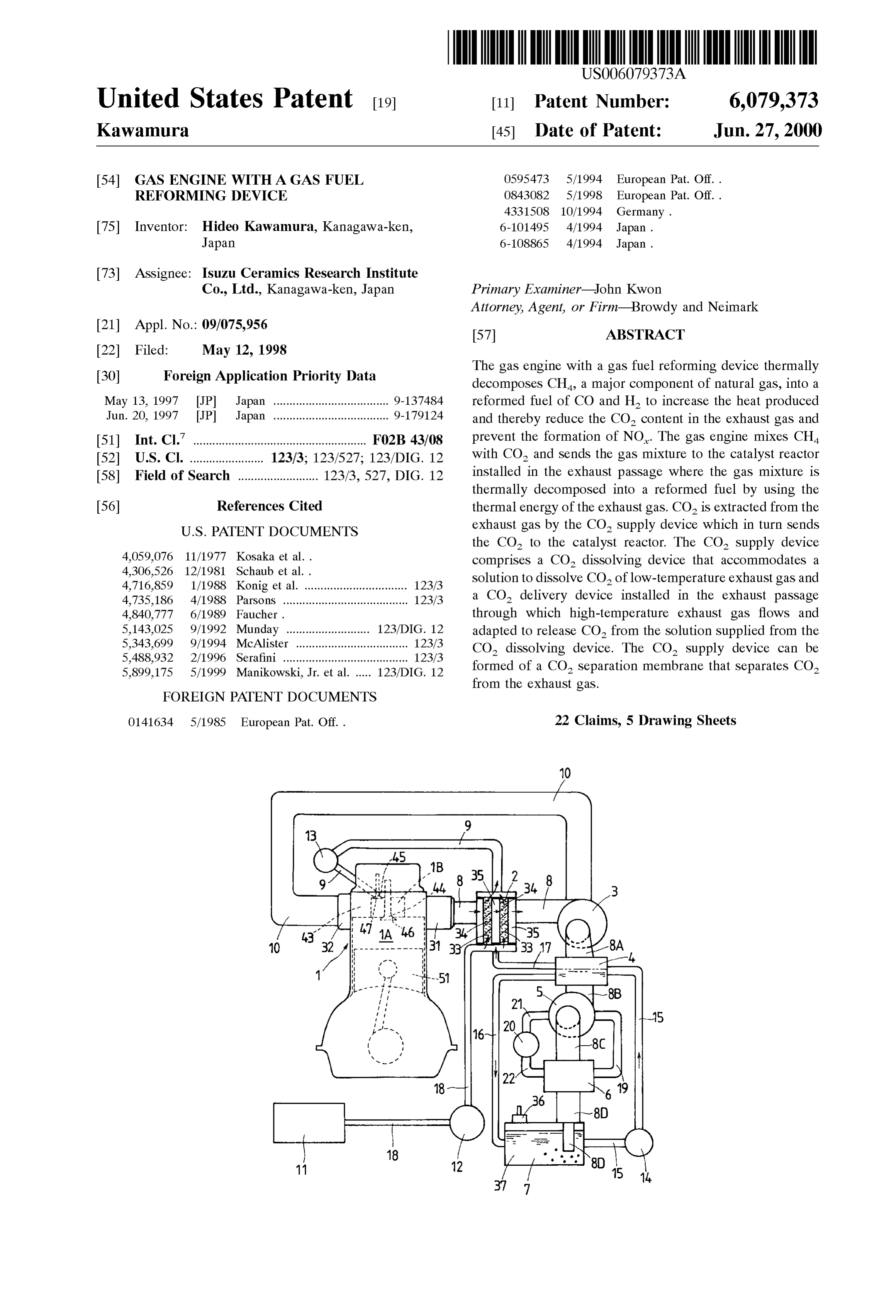
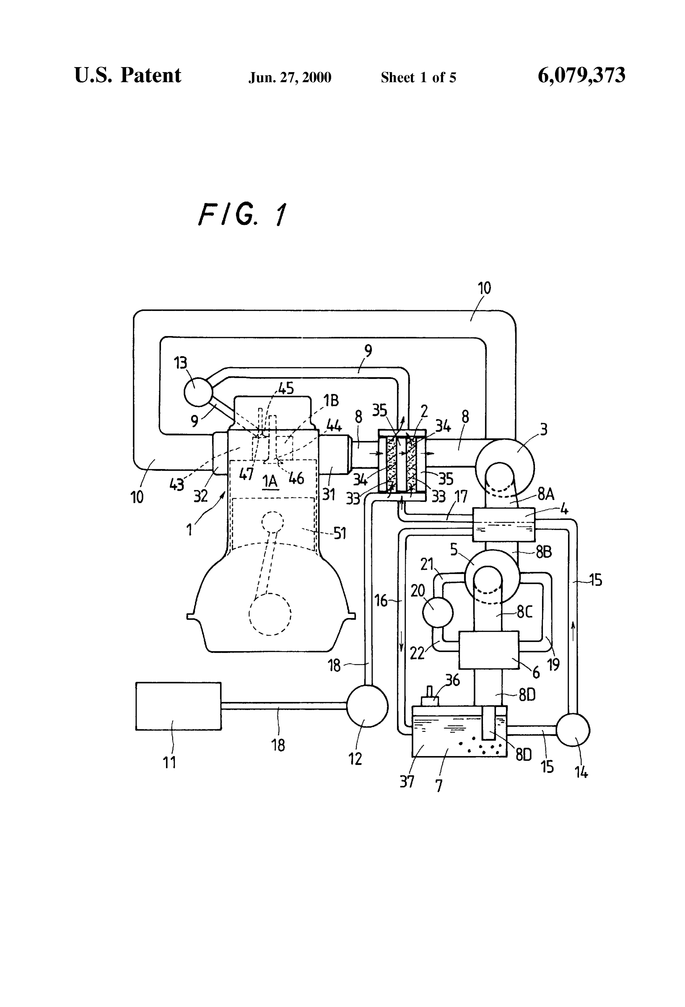
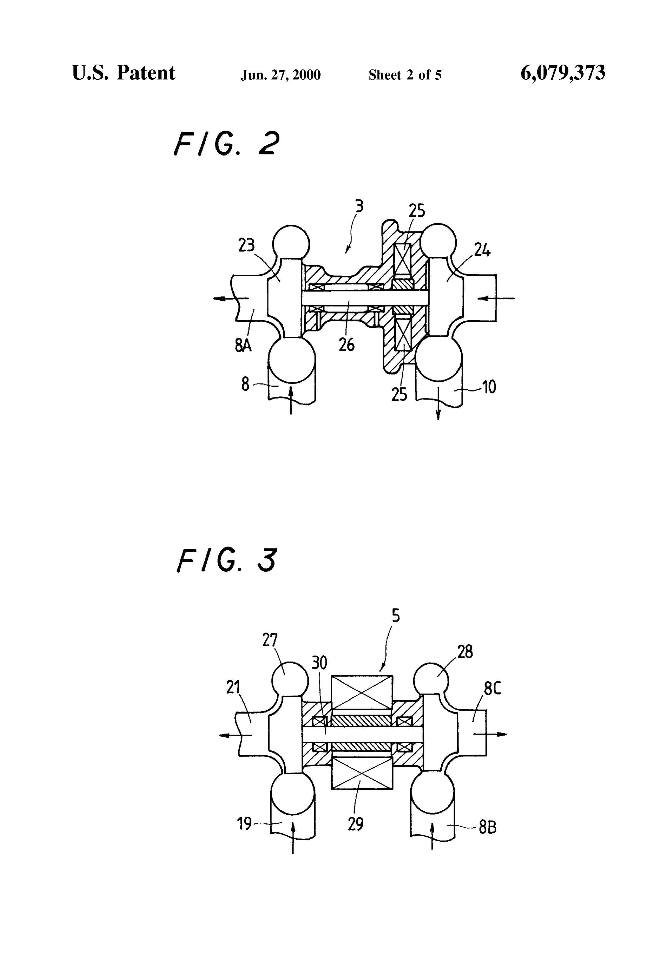
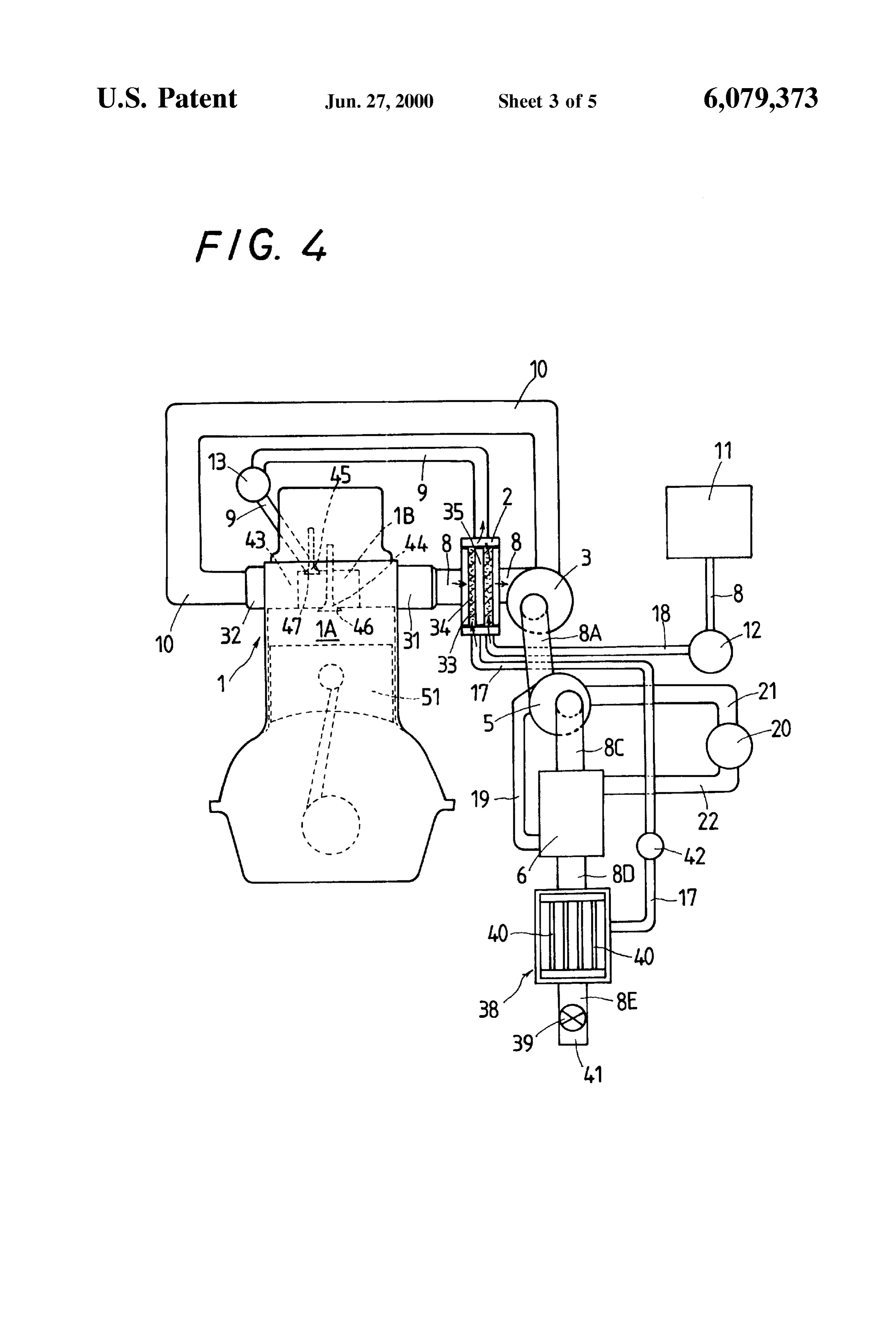
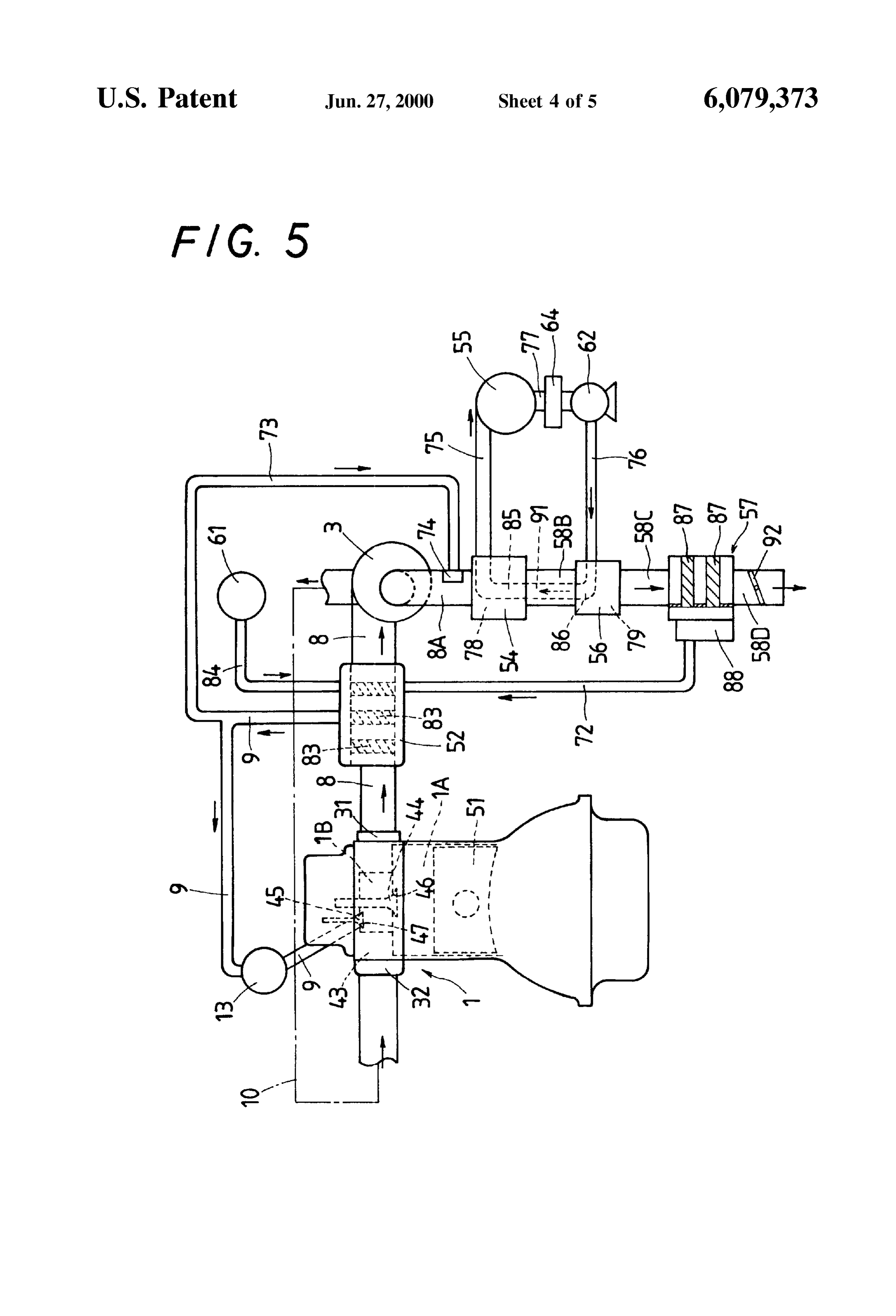
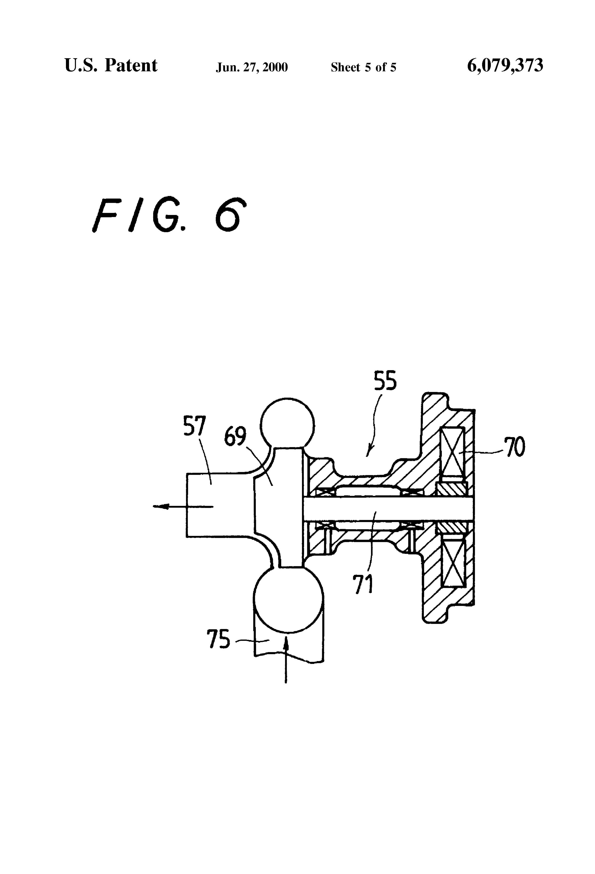
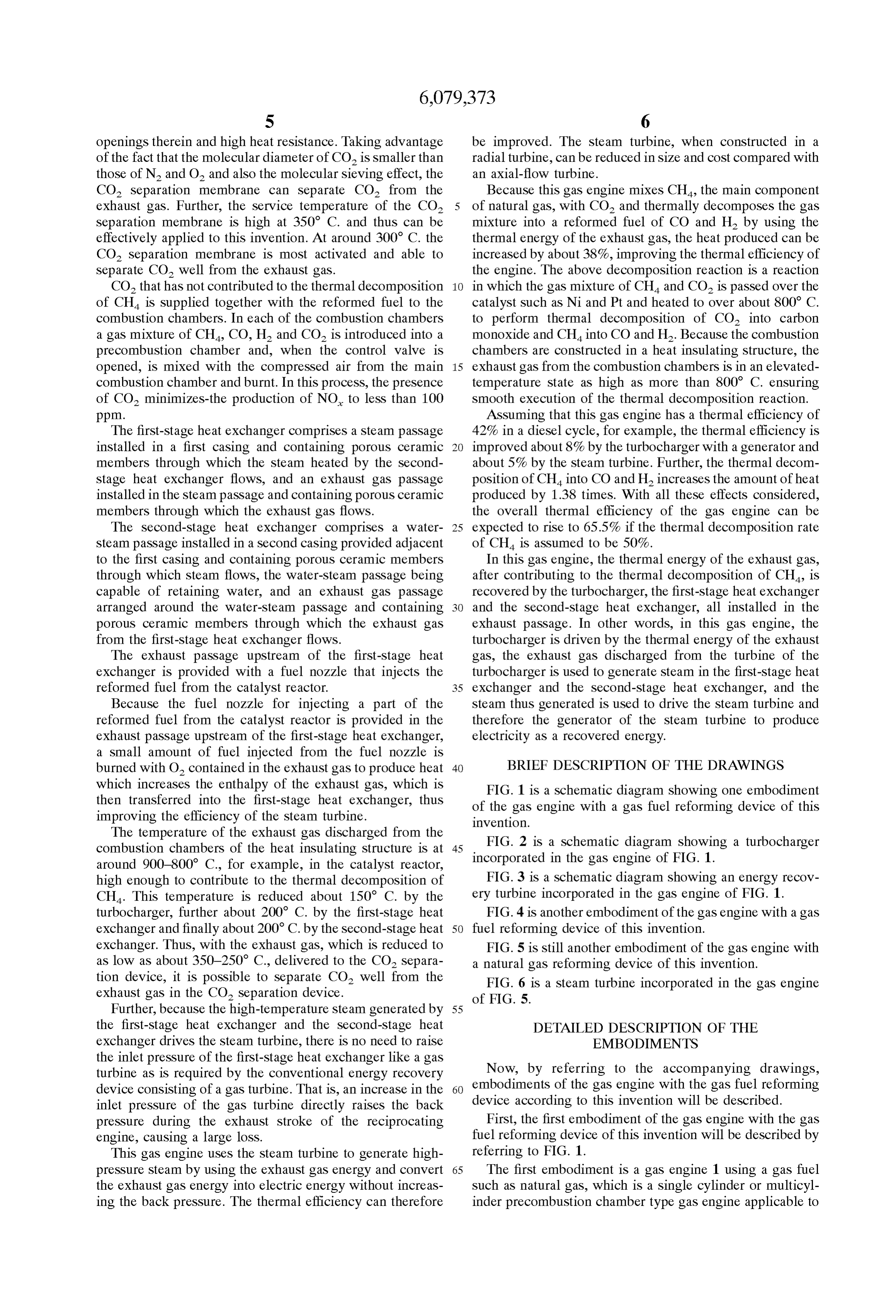
a Small amount of fuel injected from the fuel nozzle is burned with O. contained in the exhaust gas to produce heat 40 BRIEF DESCRIPTION OF THE DRAWINGS which increases the enthalpy of the exhaust gas, which is then transferred into the first-stage heat eXchanger, thus of FIG. the 1 is a Schematic diagram showing one embodiment gas engine with a gas fuel reforming device of this improving the efficiency of the Steam turbine. invention.
The temperature of the exhaust gas discharged from the FIG. 2 is a Schematic diagram showing a turbocharger combustion chambers of the heat insulating structure is at 45 incorporated in the gas engine of FIG. 1. around 900-800° C., for example, in the catalyst reactor, high enough to contribute to the thermal decomposition of FIG. 3 is a Schematic diagram showing an energy recov CH. This temperature is reduced about 150° C. by the ery turbine incorporated in the gas engine of FIG. 1. turbocharger, further about 200 C. by the first-stage heat FIG. 4 is another embodiment of the gas engine with a gas exchanger and finally about 200 C. by the second-stage heat 50 fuel reforming device of this invention. eXchanger. Thus, with the exhaust gas, which is reduced to FIG. 5 is still another embodiment of the gas engine with as low as about 350-250 C., delivered to the CO separa a natural gas reforming device of this invention. tion device, it is possible to Separate CO well from the FIG. 6 is a Steam turbine incorporated in the gas engine exhaust gas in the CO Separation device. of FIG. 5.
Further, because the high-temperature Steam generated by 55 the first-stage heat eXchanger and the Second-stage heat DETAILED DESCRIPTION OF THE eXchanger drives the Steam turbine, there is no need to raise EMBODIMENTS the inlet pressure of the first-stage heat eXchanger like a gas turbine as is required by the conventional energy recovery Now, by referring to the accompanying drawings, device consisting of a gas turbine. That is, an increase in the 60 embodiments of the gas engine with the gas fuel reforming inlet pressure of the gas turbine directly raises the back device according to this invention will be described. preSSure during the exhaust Stroke of the reciprocating First, the first embodiment of the gas engine with the gas engine, causing a large loSS. fuel reforming device of this invention will be described by This gas engine uses the Steam turbine to generate high referring to FIG. 1.
preSSure Steam by using the exhaust gas energy and convert 65 The first embodiment is a gas engine 1 using a gas fuel the exhaust gas energy into electric energy without increas Such as natural gas, which is a Single cylinder or multicyl ing the back preSSure. The thermal efficiency can therefore inder precombustion chamber type gas engine applicable to
Page 10
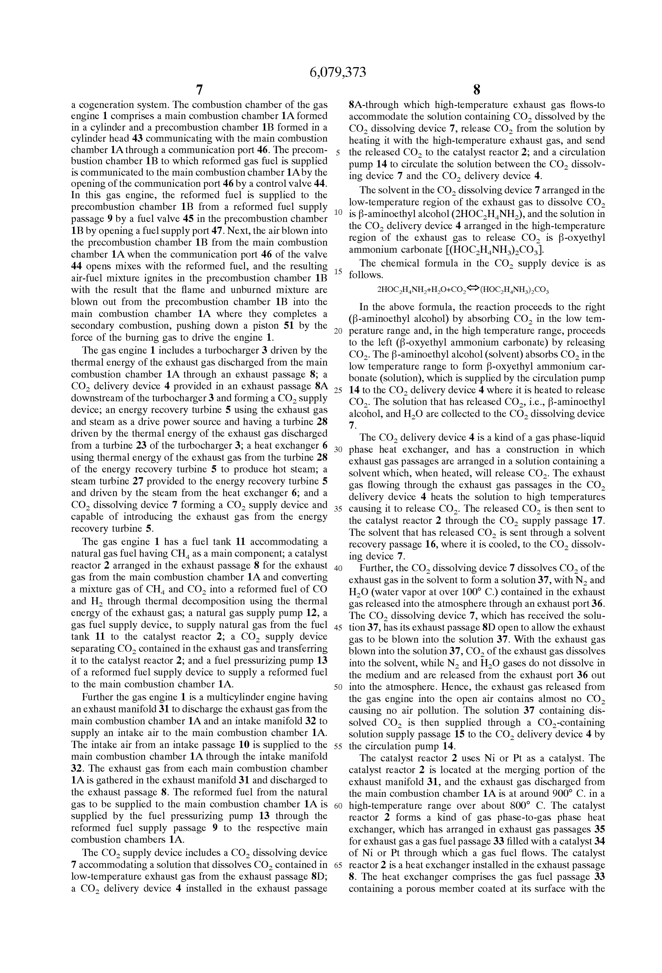
a cogeneration System. The combustion chamber of the gas 8A-through which high-temperature exhaust gas flows-to engine 1 comprises a main combustion chamber 1A formed accommodate the Solution containing CO dissolved by the in a cylinder and a precombustion chamber 1B formed in a CO dissolving device 7, release CO from the solution by cylinder head 43 communicating with the main combustion heating it with the high-temperature exhaust gas, and Send chamber 1A through a communication port 46. The precom the released CO to the catalyst reactor 2, and a circulation bustion chamber 1B to which reformed gas fuel is supplied pump 14 to circulate the solution between the CO dissolv is communicated to the main combustion chamber 1A by the ing device 7 and the CO delivery device 4. opening of the communication port 46 by a control valve 44. The solvent in the CO dissolving device 7 arranged in the In this gas engine, the reformed fuel is Supplied to the low-temperature region of the exhaust gas to dissolve CO2 precombustion chamber 1B from a reformed fuel Supply 1O passage 9 by a fuel valve 45 in the precombustion chamber is f-aminoethyl alcohol (2HOCHNH), and the solution in the CO delivery device 4 arranged in the high-temperature 1B by opening a fuel Supply port 47. Next, the air blown into region of the exhaust gas to release CO is f-oxyethyl the precombustion chamber 1B from the main combustion chamber 1A when the communication port 46 of the valve ammonium carbonate (HOCHNH)2CO). The chemical formula in the CO Supply device is as 44 opens mixes with the reformed fuel, and the resulting 15 follows.
air-fuel mixture ignites in the precombustion chamber 1B with the result that the flame and unburned mixture are blown out from the precombustion chamber 1B into the In the above formula, the reaction proceeds to the right main combustion chamber 1A where they completes a (B-aminoethyl alcohol) by absorbing CO in the low tem Secondary combustion, pushing down a piston 51 by the perature range and, in the high temperature range, proceeds force of the burning gas to drive the engine 1. to the left (B-oxyethyl ammonium carbonate) by releasing The gas engine 1 includes a turbocharger 3 driven by the CO. The B-aminoethyl alcohol (solvent) absorbs CO in the thermal energy of the exhaust gas discharged from the main low temperature range to form B-Oxyethyl ammonium car combustion chamber 1A through an exhaust passage 8; a bonate (Solution), which is Supplied by the circulation pump CO delivery device 4 provided in an exhaust passage 8A 25 to the CO delivery device 4 where it is heated to release downstream of the turbocharger 3 and forming a CO Supply 14 CO. The Solution that has released CO, i.e., f-aminoethyl device; an energy recovery turbine 5 using the exhaust gas alcohol, and HO are collected to the CO dissolving device and Steam as a drive power Source and having a turbine 28 7.
driven by the thermal energy of the exhaust gas discharged The CO delivery device 4 is a kind of a gas phase-liquid from a turbine 23 of the turbocharger 3; a heat exchanger 6 phase heat eXchanger, and has a construction in which using thermal energy of the exhaust gas from the turbine 28 exhaust gas passages are arranged in a Solution containing a of the energy recovery turbine 5 to produce hot Steam; a solvent which, when heated, will release CO. The exhaust steam turbine 27 provided to the energy recovery turbine 5 gas flowing through the exhaust gas passages in the CO and driven by the Steam from the heat eXchanger 6, and a delivery device 4 heats the Solution to high temperatures CO2 dissolving device 7 forming a CO Supply device and 35 capable of introducing the exhaust gas from the energy causing it to release CO. The released CO is then sent to the catalyst reactor 2 through the CO Supply passage 17.
recovery turbine 5. The solvent that has released CO is sent through a solvent The gas engine 1 has a fuel tank 11 accommodating a recovery passage 16, where it is cooled, to the CO dissolv natural gas fuel having CH as a main component; a catalyst ing device 7.
reactor 2 arranged in the exhaust passage 8 for the exhaust 40 Further, the CO dissolving device 7 dissolves CO of the gas from the main combustion chamber 1A and converting exhaust gas in the solvent to form a solution 37, with N and a mixture gas of CH and CO into a reformed fuel of CO HO (water vapor at over 100° C.) contained in the exhaust and H through thermal decomposition using the thermal gas released into the atmosphere through an exhaust port 36. energy of the exhaust gas, a natural gas Supply pump 12, a The CO dissolving device 7, which has received the solu gas fuel Supply device, to Supply natural gas from the fuel 45 tion 37, has its exhaust passage 8D open to allow the exhaust tank 11 to the catalyst reactor 2, a CO Supply device gas to be blown into the solution 37. With the exhaust gas Separating CO contained in the exhaust gas and transferring blown into the solution37, CO of the exhaust gas dissolves it to the catalyst reactor 2, and a fuel pressurizing pump 13 into the solvent, while N and HO gases do not dissolve in of a reformed fuel Supply device to Supply a reformed fuel the medium and are released from the exhaust port 36 out to the main combustion chamber 1A. 50 into the atmosphere. Hence, the exhaust gas released from Further the gas engine 1 is a multicylinder engine having the gas engine into the open air contains almost no CO2 an exhaust manifold 31 to discharge the exhaust gas from the causing no air pollution. The Solution 37 containing dis main combustion chamber 1A and an intake manifold 32 to Solved CO2 is then Supplied through a CO-containing Supply an intake air to the main combustion chamber 1A. solution supply passage 15 to the CO delivery device 4 by The intake air from an intake passage 10 is Supplied to the 55 the circulation pump 14.
main combustion chamber 1A through the intake manifold The catalyst reactor 2 uses Ni or Pt as a catalyst. The 32. The exhaust gas from each main combustion chamber catalyst reactor 2 is located at the merging portion of the 1A is gathered in the exhaust manifold 31 and discharged to exhaust manifold 31, and the exhaust gas discharged from the exhaust passage 8. The reformed fuel from the natural the main combustion chamber 1A is at around 900 C. in a gas to be Supplied to the main combustion chamber 1A is 60 high-temperature range over about 800° C. The catalyst Supplied by the fuel preSSurizing pump 13 through the reactor 2 forms a kind of gas phase-to-gas phase heat reformed fuel Supply passage 9 to the respective main eXchanger, which has arranged in exhaust gas passages 35 combustion chambers 1A. for exhaust gas a gas fuel passage 33 filled with a catalyst 34 The CO Supply device includes a CO2 dissolving device of Ni or Pt through which a gas fuel flows. The catalyst 7 accommodating a Solution that dissolves CO contained in 65 reactor 2 is a heat eXchanger installed in the exhaust passage low-temperature exhaust gas from the exhaust passage 8D, 8. The heat eXchanger comprises the gas fuel passage 33 a CO delivery device 4 installed in the exhaust passage containing a porous member coated at its Surface with the
Page 11
catalyst 34, the catalyst being incorporated inside the Sepa The solvent in the CO dissolving device 7 to dissolve ration wall between the passages through which the exhaust CO may use diethanolamine in addition to the above gas flows. f3-aminoethyl alcohol. Diethanolamine (HOCH2CH)NH The high-temperature exhaust gas from the main com has characteristics of absorbing CO2 at low temperature and bustion chamber 1A flowing through the exhaust gas pas releasing CO at high temperature, as does B-aminoethyl Sages 35 in the catalyst reactor 2 heats the gas fuel passage alcohol. With the use of diethanolamine, too, the CO 33 filled with the catalyst 34 of Nior Pt. The gas mixture of delivery device 4 can, as described above, release CO and CH and CO2 flowing through the gas fuel passage 33 heated Send it to the catalyst reactor 2, which in turn thermally to over approximately 800° C. contact the catalyst with the decomposes the gas mixture of CH and CO contained in result that CH is thermally decomposed into CO and H and the natural gas into CO and H with the aid of the catalyst. CO into CO, transforming the gas fuel into the reformed The exhaust gas is removed of CO when it is blown into the fuel of CO and H. Next, the reformed fuel transformed from CO dissolving device 7 containing the solvent of dietha the natural gas is Supplied by the fuel pressurizing pump 13 nolamine and then released into the atmosphere as a very through the reformed fuel Supply passage 9 and the intake clean exhaust gas consisting of N and H2O (water vapor at manifold 32 into the respective main combustion chambers 15 more than 100° C.) gases.
1A. Next, by referring to FIG. 4, let us explain about the Because the gas engine 1 is constructed in a heat insu Second embodiment of the gas engine having a gas fuel lating Structure made of a ceramic member and a heat reforming device of this invention.
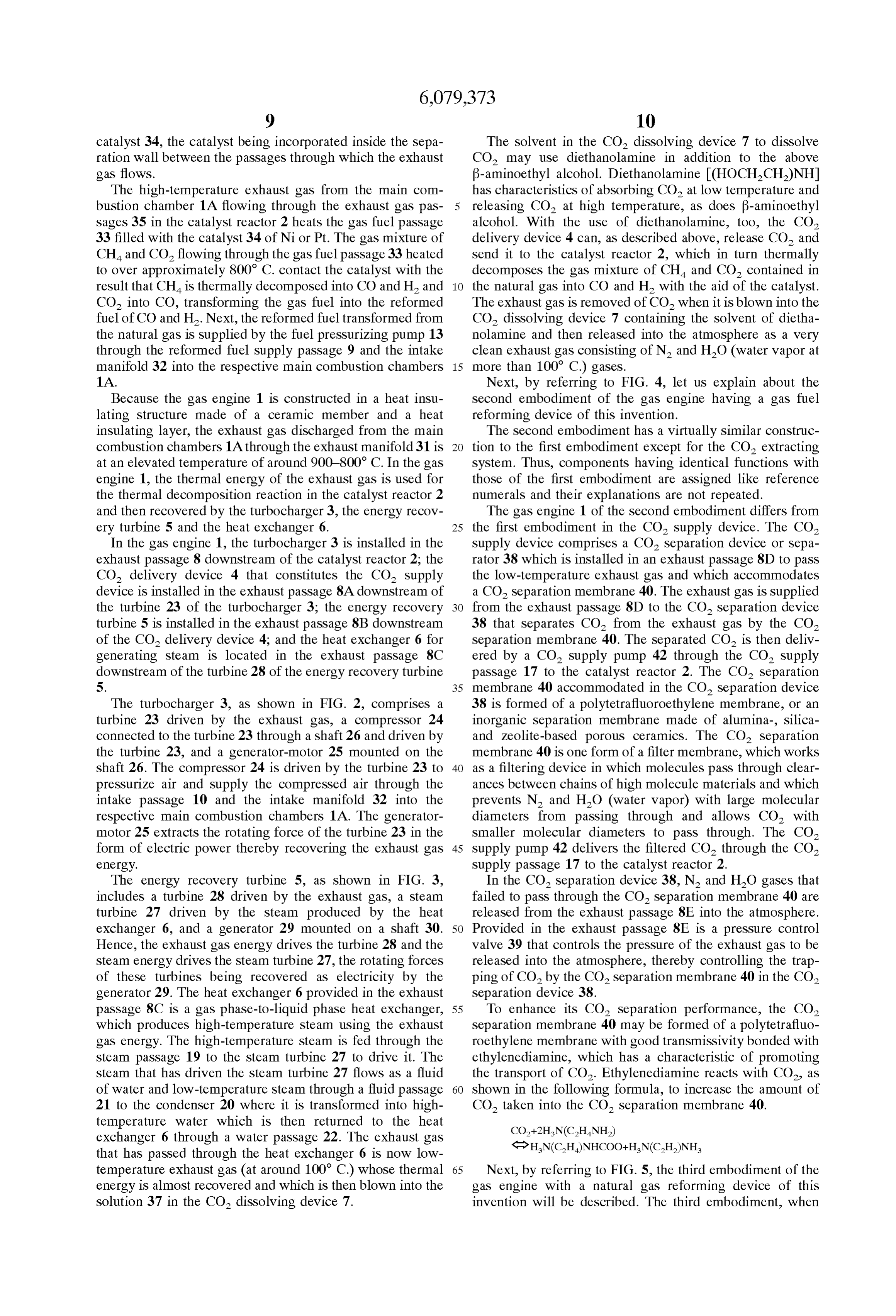
insulating layer, the exhaust gas discharged from the main The Second embodiment has a virtually similar construc combustion chambers 1A through the exhaust manifold 31 is tion to the first embodiment except for the CO2 extracting at an elevated temperature of around 900-800° C. In the gas System. Thus, components having identical functions with engine 1, the thermal energy of the exhaust gas is used for those of the first embodiment are assigned like reference the thermal decomposition reaction in the catalyst reactor 2 numerals and their explanations are not repeated. and then recovered by the turbocharger 3, the energy recov The gas engine 1 of the second embodiment differs from ery turbine 5 and the heat exchanger 6. 25 the first embodiment in the CO Supply device. The CO In the gas engine 1, the turbocharger 3 is installed in the Supply device comprises a CO2 Separation device or Sepa exhaust passage 8 downstream of the catalyst reactor 2; the rator 38 which is installed in an exhaust passage 8D to pass CO delivery device 4 that constitutes the CO supply the low-temperature exhaust gas and which accommodates device is installed in the exhaust passage 8A downstream of a CO2 Separation membrane 40. The exhaust gas is Supplied the turbine 23 of the turbocharger 3; the energy recovery from the exhaust passage 8D to the CO Separation device turbine 5 is installed in the exhaust passage 8B downstream 38 that separates CO from the exhaust gas by the CO of the CO delivery device 4; and the heat exchanger 6 for separation membrane 40. The separated CO is then deliv generating Steam is located in the exhaust passage 8C ered by a CO Supply pump 42 through the CO Supply downstream of the turbine 28 of the energy recovery turbine passage 17 to the catalyst reactor 2. The CO2 Separation 5. 35 membrane 40 accommodated in the CO Separation device The turbocharger 3, as shown in FIG. 2, comprises a 38 is formed of a polytetrafluoroethylene membrane, or an turbine 23 driven by the exhaust gas, a compressor 24 inorganic Separation membrane made of alumina-, Silica connected to the turbine 23 through a shaft 26 and driven by and Zeolite-based porous ceramics. The CO2 Separation the turbine 23, and a generator-motor 25 mounted on the membrane 40 is one form of a filter membrane, which works shaft 26. The compressor 24 is driven by the turbine 23 to 40 as a filtering device in which molecules pass through clear preSSurize air and Supply the compressed air through the ances between chains of high molecule materials and which intake passage 10 and the intake manifold 32 into the prevents N and HO (water vapor) with large molecular respective main combustion chambers 1A. The generator diameters from passing through and allows CO with motor 25 extracts the rotating force of the turbine 23 in the Smaller molecular diameters to pass through. The CO2 form of electric power thereby recovering the exhaust gas 45 supply pump 42 delivers the filtered CO through the CO energy. Supply passage 17 to the catalyst reactor 2. The energy recovery turbine 5, as shown in FIG. 3, In the CO, separation device 38, N and HO gases that includes a turbine 28 driven by the exhaust gas, a Steam failed to pass through the CO2 Separation membrane 40 are turbine 27 driven by the steam produced by the heat released from the exhaust passage 8E into the atmosphere. exchanger 6, and a generator 29 mounted on a shaft 30. 50 Provided in the exhaust passage 8E is a preSSure control Hence, the exhaust gas energy drives the turbine 28 and the valve 39 that controls the pressure of the exhaust gas to be Steam energy drives the Steam turbine 27, the rotating forces released into the atmosphere, thereby controlling the trap of these turbines being recovered as electricity by the ping of CO by the CO2 separation membrane 40 in the CO generator 29. The heat exchanger 6 provided in the exhaust separation device 38.
passage 8C is a gas phase-to-liquid phase heat eXchanger, 55 To enhance its CO2 Separation performance, the CO2 which produces high-temperature Steam using the exhaust separation membrane 40 may be formed of a polytetrafluo gas energy. The high-temperature Steam is fed through the roethylene membrane with good transmissivity bonded with steam passage 19 to the steam turbine 27 to drive it. The ethylenediamine, which has a characteristic of promoting steam that has driven the steam turbine 27 flows as a fluid the transport of CO2. Ethylenediamine reacts with CO2, as of water and low-temperature Steam through a fluid passage 60 shown in the following formula, to increase the amount of 21 to the condenser 20 where it is transformed into high CO taken into the CO, separation membrane 40. temperature water which is then returned to the heat eXchanger 6 through a water passage 22. The exhaust gas that has passed through the heat eXchanger 6 is now low temperature exhaust gas (at around 100 C.) whose thermal 65 Next, by referring to FIG. 5, the third embodiment of the energy is almost recovered and which is then blown into the gas engine with a natural gas reforming device of this solution 37 in the CO dissolving device 7. invention will be described. The third embodiment, when
Page 12
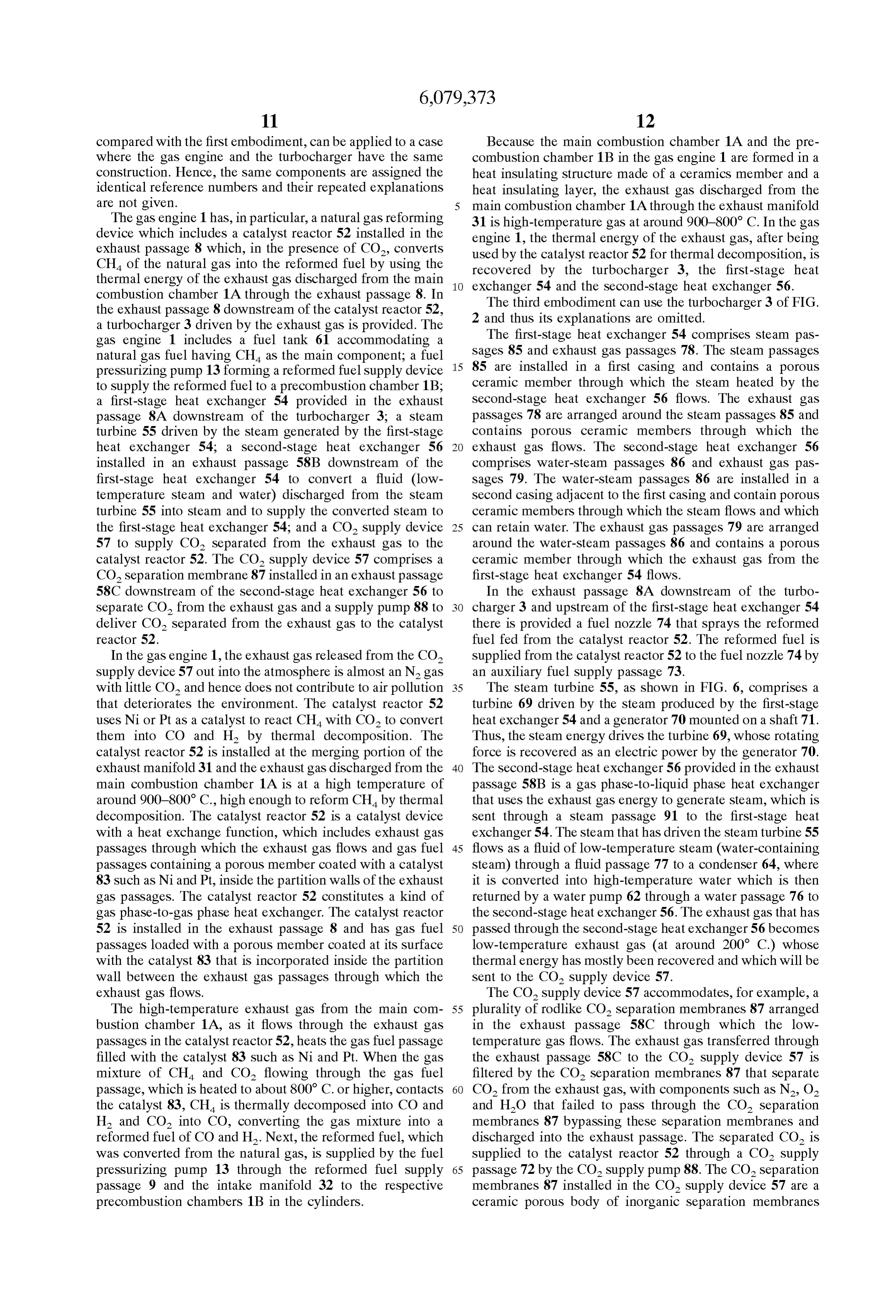
compared with the first embodiment, can be applied to a case Because the main combustion chamber 1A and the pre where the gas engine and the turbocharger have the same combustion chamber 1B in the gas engine 1 are formed in a construction. Hence, the same components are assigned the heat insulating Structure made of a ceramicS member and a identical reference numbers and their repeated explanations heat insulating layer, the exhaust gas discharged from the are not given. main combustion chamber 1A through the exhaust manifold The gas engine 1 has, in particular, a natural gas reforming 31 is high-temperature gas at around 900-800° C. In the gas device which includes a catalyst reactor 52 installed in the engine 1, the thermal energy of the exhaust gas, after being exhaust passage 8 which, in the presence of CO, converts used by the catalyst reactor 52 for thermal decomposition, is CH of the natural gas into the reformed fuel by using the thermal energy of the exhaust gas discharged from the main recovered eXchanger by the turbocharger 3, the first-stage heat 54 and the Second-stage heat eXchanger 56.
combustion chamber 1A through the exhaust passage 8. In The third embodiment can use the turbocharger 3 of FIG. the exhaust passage 8 downstream of the catalyst reactor 52, 2 and thus its explanations are omitted. a turbocharger 3 driven by the exhaust gas is provided. The The first-stage heat eXchanger 54 comprises Steam pas gas engine 1 includes a fuel tank 61 accommodating a natural gas fuel having CH as the main component; a fuel 15 Sages 85 and exhaust gas passages 78. The Steam passages preSSurizing pump 13 forming a reformed fuel Supply device 85 are installed in a first casing and contains a porous to supply the reformed fuel to a precombustion chamber 1B: ceramic member through which the Steam heated by the a first-stage heat eXchanger 54 provided in the exhaust Second-Stage heat eXchanger 56 flows. The exhaust gas passage 8A downstream of the turbocharger 3, a Steam passages 78 are arranged around the Steam passages 85 and turbine 55 driven by the steam generated by the first-stage contains porous ceramic members through which the heat eXchanger 54, a Second-stage heat eXchanger 56 exhaust gas flows. The Second-Stage heat eXchanger 56 installed in an exhaust passage 58B downstream of the comprises water-Steam passageS 86 and exhaust gas pas first-stage heat exchanger 54 to convert a fluid (low Sages 79. The water-Steam passages 86 are installed in a temperature Steam and water) discharged from the Steam Second casing adjacent to the first casing and contain porous turbine 55 into steam and to supply the converted steam to ceramic members through which the Steam flows and which the first-Stage heat eXchanger 54; and a CO Supply device 25 can retain water. The exhaust gas passages 79 are arranged 57 to supply CO separated from the exhaust gas to the around the water-Steam passages 86 and contains a porous catalyst reactor 52. The CO supply device 57 comprises a ceramic member through which the exhaust gas from the CO Separation membrane 87 installed in an exhaust passage first-stage heat eXchanger 54 flows. 58C downstream of the second-stage heat exchanger 56 to In the exhaust passage 8A downstream of the turbo Separate CO from the exhaust gas and a Supply pump 88 to charger 3 and upstream of the first-Stage heat eXchanger 54 deliver CO2 Separated from the exhaust gas to the catalyst there is provided a fuel nozzle 74 that sprays the reformed reactor 52. fuel fed from the catalyst reactor 52. The reformed fuel is In the gas engine 1, the exhaust gas released from the CO Supplied from the catalyst reactor 52 to the fuel nozzle 74 by Supply device 57 out into the atmosphere is almost an Nagas an auxiliary fuel Supply passage 73. with little CO and hence does not contribute to air pollution 35 The steam turbine 55, as shown in FIG. 6, comprises a that deteriorates the environment. The catalyst reactor 52 turbine 69 driven by the steam produced by the first-stage uses Nior Pt as a catalyst to react CH with CO to convert heat exchanger 54 and a generator 70 mounted on a shaft 71. them into CO and H by thermal decomposition. The Thus, the steam energy drives the turbine 69, whose rotating catalyst reactor 52 is installed at the merging portion of the force is recovered as an electric power by the generator 70. exhaust manifold 31 and the exhaust gas discharged from the 40 The Second-Stage heat eXchanger 56 provided in the exhaust main combustion chamber 1A is at a high temperature of passage 58B is a gas phase-to-liquid phase heat eXchanger around 900-800° C., high enough to reform CH by thermal that uses the exhaust gas energy to generate Steam, which is decomposition. The catalyst reactor 52 is a catalyst device Sent through a Steam passage 91 to the first-stage heat with a heat eXchange function, which includes exhaust gas exchanger 54. The steam that has driven the steam turbine 55 passages through which the exhaust gas flows and gas fuel 45 flows as a fluid of low-temperature Steam (water-containing passages containing a porous member coated with a catalyst Steam) through a fluid passage 77 to a condenser 64, where 83 Such as Ni and Pt, inside the partition walls of the exhaust it is converted into high-temperature water which is then gas passages. The catalyst reactor 52 constitutes a kind of returned by a water pump 62 through a water passage 76 to gas phase-to-gas phase heat eXchanger. The catalyst reactor the Second-Stage heat eXchanger 56. The exhaust gas that has 52 is installed in the exhaust passage 8 and has gas fuel 50 passed through the Second-stage heat eXchanger 56 becomes passages loaded with a porous member coated at its Surface low-temperature exhaust gas (at around 200° C.) whose with the catalyst 83 that is incorporated inside the partition thermal energy has mostly been recovered and which will be wall between the exhaust gas passages through which the sent to the CO Supply device 57.
exhaust gas flows. The CO Supply device 57 accommodates, for example, a The high-temperature exhaust gas from the main com 55 plurality of rodlike CO separation membranes 87 arranged bustion chamber 1A, as it flows through the exhaust gas in the exhaust passage 58C through which the low passages in the catalyst reactor 52, heats the gas fuel passage temperature gas flows. The exhaust gas transferred through filled with the catalyst 83 Such as Ni and Pt. When the gas the exhaust passage 58C to the CO Supply device 57 is mixture of CH and CO2 flowing through the gas fuel filtered by the CO2 separation membranes 87 that separate passage, which is heated to about 800 C. or higher, contacts 60 CO2 from the exhaust gas, with components Such as N, O, the catalyst 83, CH is thermally decomposed into CO and and H2O that failed to pass through the CO2 separation H and CO2 into CO, converting the gas mixture into a membranes 87 bypassing these Separation membranes and reformed fuel of CO and H. Next, the reformed fuel, which discharged into the exhaust passage. The separated CO is was converted from the natural gas, is Supplied by the fuel Supplied to the catalyst reactor 52 through a CO Supply preSSurizing pump 13 through the reformed fuel Supply 65 passage 72 by the CO Supply pump 88. The CO separation passage 9 and the intake manifold 32 to the respective membranes 87 installed in the CO Supply device 57 are a precombustion chambers 1B in the cylinders. ceramic porous body of inorganic Separation membranes
Page 13
made of alumina-, Silica- and Zeolite-based porous ceramics. steam passage 75 to the steam turbine 55 which drives the These Separation membranes are a kind of filter membrane turbine 69 to cause the generator 70 to generate electricity. that passes CO with Small molecular diameters. and blockS The electricity produced by the generator 70 is stored in a N, O and HO (water vapor) with large molecular diam battery or consumed for driving auxiliary equipment. The eters. The CO is then supplied by the CO Suction supply high-temperature Steam, after driving the Steam turbine 55, pump 88 through the CO Supply passage 72 to the catalyst is converted into a fluid of low-temperature Steam and water, reactor 52. which is then delivered through the fluid passage 77 to the In the CO Supply device 57, N and HO (water vapor) condenser 64 where it is condensed into water, which is that failed to pass through the CO separation membranes 87 Supplied by the water pump 62 through the water passage 76 are released from an exhaust passage 58D into the atmo to the water-Steam passage 86 in the Second-stage heat Sphere. The exhaust passage 58D is provided, for example, exchanger 56.
with a pressure control valve 92, which controls the pressure The exhaust gas transferred from the first-stage heat of the exhaust gas to be released into the open air and eXchanger 54 to the Second-stage heat eXchanger 56 flows therefore the amount of CO taken in by the CO Suction supply pump 88 through the CO, separation membranes 87 through 58C. The the exhaust gas passages 79 to the exhaust passage exhaust gas, as it passes through the exhaust gas in the CO Supply device 57. 15
The gas engine with this natural gas reforming device is passages 79, transforms water flowing through the water Steam passageS 86 into Steam by heat eXchange. Because its constructed as described above and works as follows.
With a control valve 44 closed, the air is supplied into the thermal energy is already recovered by the catalyst reactor main combustion chamber 1A from the compressor 24 of the 52, the turbocharger 3, the first-stage heat eXchanger 54 and turbocharger 3 through the intake passage 10 and the intake the Second-stage heat eXchanger 56, the exhaust gas deliv manifold 32 upon the opening of the intake valve (not downtototheabout ered exhaust passage 58C has its temperature reduced 200° C. and thus does not damage the CO shown). The air in the main combustion chamber 1A is separation membranes 87 when it is fed into the CO supply compressed during the compression Stroke, with the control valve 44 still closed. The natural gas fuel is supplied from device 57. The exhaust gas delivered into the CO supply device 57 passes through the CO separation membranes 87 the fuel tank 61 through a natural gas Supply passage 84 to to the catalyst reactor 52 where it is converted into a reformed thebeCO 25 cleared of CO. The separated CO is then delivered by
Suction supply pump 88 from the CO supply fuel. At the same time, with the control valve 44 closed, the fuel valve 45 is opened and the fuel pressurizing pump 13 is reactor 52.through device 57 the CO Supply passage 72 to the catalyst
Filtering the exhaust gas through the CO2 Sepa activated to Supply the reformed fuel from the catalyst reactor 52 through the reformed fuel Supply passage 9 to the ration membranes 87 Separates CO from the exhaust gas, and the exhaust gas from which CO is separated includes precombustion chamber 1B. The control valve 44 is now Such opened near the top dead center during the compression CO components as N and HO with the reduced content of and is released from the exhaust passage 58D out into
Stroke, allowing the compressed air in the main combustion the atmosphere.
chamber 1A to flow into the precombustion chamber 1B and What is claimed is:
mix with the reformed fuel, igniting and burning the air-fuel 1. A gas engine with a gas fuel reforming device, com mixture to perform the work on the piston 51 during the 35 prising:
power Stroke.
In the exhaust Stroke, the exhaust gas of the main com a fuel tank containing a natural gas fuel having CH as a bustion chamber 1A and the precombustion chamber 1B is major component;
discharged through the exhaust passage 8. The high an exhaust passage to discharge exhaust gas from com temperature exhaust gas, as it passes through the catalyst 40 bustion chambers, reactor 52, converts the natural gas into a reformed fuel by a catalyst reactor installed in the exhaust passage to its thermal energy and is then Sent to the turbocharger 3. The thermally decompose a gas mixture of CH and CO turbocharger 3 now drives the turbine 23 whose rotating into a reformed fuel of CO and H by using thermal force is converted by the generator-motor 25 into an electric energy of the exhaust gas, energy and also drives the compressor 24. The electric a gas fuel Supply device to Supply the natural gas fuel power obtained by the generator-motor 25 is Stored in a 45 from the fuel tank to the catalyst reactor; battery or consumed for driving auxiliary equipment. The compressor 24 Supplies air through the intake passage 10 to a CO Supply device to Supply to the catalyst reactor CO2 the main combustion chamber 1A. The exhaust gas that has Separated from the exhaust gas by a CO separator; and passed through the turbine 23 of the turbocharger 3 is sent a reformed fuel Supply device to Supply the reformed fuel through the exhaust passage 8A to the first-Stage heat 50 to the combustion chambers, eXchanger 54. wherein the combustion chambers are formed in a heat The exhaust passage 8A is provided with the fuel nozzle insulating structure of a ceramic member. 74 that Sprays into the exhaust passage 8A a part of the 2. A gas engine according to claim 1, wherein the CO reformed fuel Supplied from the catalyst reactor 52 through Supply device comprises: a CO2 dissolving device of the the auxiliary fuel Supply passage 73. Because the exhaust 55 CO Separator containing a Solution to dissolve CO of a gas flowing through the exhaust passage 8A contains a large cooled, low-temperature exhaust gas, a CO delivery device amount of O, the reformed fuel injected from the fuel installed in the exhaust passage through which high nozzle 74 ignites and burns increasing enthalpy of the temperature exhaust gas discharged from the combustion exhaust gas. The exhaust gas fed into the first-stage heat chambers flows, the CO delivery device being able to eXchanger 54 flows through the exhaust gas passages 78 and 60 release CO2 from the solution, in which CO was dissolved then through the exhaust passage 58B into the Second-stage by the CO dissolving device, by heating the solution with heat eXchanger 56. The exhaust gas, as it passes through the the high-temperature exhaust gas, the CO delivery device exhaust gas passages 78, exchanges heat with the Steam that being able to accommodate the Solution and Send the was Sent from the Second-stage heat eXchanger 56 through released CO2 to the catalyst reactor, and a circulation pump the Steam passages 91 to the Steam passages 85 to heat the to circulate the Solution between the CO dissolving device Steam to high temperatures. 65 and the CO delivery device.
The Steam heated to high temperatures in the first-stage 3. A gas. engine according to claim 2, wherein a Solvent heat eXchanger 54 is Sent through the high-temperature in the CO dissolving device that absorbs CO of the exhaust
Page 14
gas is 3-aminoethyl alcohol and the Solution in the CO2 15. A gas engine according to claim 14, wherein the CO2 delivery device that releases CO is f-oxyethyl ammonium. Separation membrane is an inorganic Separation membrane 4. A gas engine according to claim 2, wherein the Solvent made of alumina-, Silica- and Zeolite-based porous ceramics. in the CO dissolving device that dissolves CO is dietha 16. A gas engine according to claim 14, wherein the nolamine.
5. A gas engine according to claim 1, wherein the CO2 catalyst reactor reacts CH with CO2 to thermally decom dissolving device dissolves CO of the exhaust gas in a pose them into CO and H by using Nior Pt as a catalyst. 17. A gas engine according to claim 14, wherein the solvent to form a solution and releases N and HO of the catalyst reactor is a catalyst device having a heat eXchange exhaust gas out into the atmosphere.
6. A gas engine according to claim 1, wherein the CO2 function, and comprises an exhaust gas passage through Supply device Supplies to the catalyst reactor CO which was which the exhaust gas flows and a gas fuel passage contain Separated from the exhaust gas by a CO2 Separation mem ing a porous member coated at its Surface with the catalyst, brane of the CO2 Separator arranged in the exhaust passage the catalyst being incorporated inside a partition wall of the through which low-temperature exhaust gas flows. exhaust gas passage.
7. A gas engine according to claim 6, wherein the CO2 18. A gas engine according to claim 14, wherein the Separation membrane in the CO Supply device is a poly 15 first-stage heat eXchanger comprises a Steam passage tetrafluoroethylene membrane. installed in a first casing and containing porous ceramic 8. A gas engine according to claim 6, wherein the CO2 members through which the Steam heated by the Second Separation membrane in the CO Supply device is a poly Stage heat eXchanger flows, and an exhaust gas passage tetrafluoroethylene membrane bonded with ethylenediamine installed in the Steam passage and containing porous ceramic to enhance a CO filtering performance. members through which the exhaust gas flows. 9. A gas engine according to claim 6, wherein the CO2 19. A gas engine according to claim 14, wherein the Separation membrane is an inorganic Separation membrane Second-Stage heat eXchanger comprises a water-Steam pas made of alumina-, Silica- and Zeolite-based porous ceramics. Sage installed in a Second casing provided adjacent to the 10. A gas engine according to claim 1, wherein the first casing and containing porous ceramic members through catalyst reactor uses Ni or Pt as a catalyst. which Steam flows, the water-Steam passage being capable 11. Agas engine according to claim 1, wherein the catalyst 25 of retaining Water, and an exhaust gas passage arranged reactor is a heat eXchanger installed in the exhaust passage, around the water-Steam passage and containing porous and the heat eXchanger comprises exhaust gas passages ceramic members through which the exhaust gas from the through which the exhaust gas flows and gas fuel passages first-stage heat eXchanger flows.
that contains porous members coated at their Surfaces with exhaust 20. A gas engine according to claim 14, wherein the the catalyst, the catalyst being incorporated inside Separation passage upstream of the first-stage heat eXchanger is walls between the exhaust gas passages. provided with a fuel nozzle to inject a part of the reformed 12. A gas engine according to claim 1, wherein a turbo fuel from the catalyst reactor.
charger is installed in the exhaust passage downstream of the 21. A gas engine according to claim 14, wherein the combustion chambers are formed in a heat insulating Struc catalyst reactor, an energy recovery turbine is installed in the ture exhaust passage downstream of the turbocharger, and a heat 35 of a ceramic member.
22. A gas engine with a gas fuel reforming device, eXchanger is installed in the exhaust passage downstream of comprising:
the energy recovery turbine to generate Steam.
13. A gas engine according to claim 1, wherein the a fuel tank containing a natural gas fuel having CH as a catalyst reactor includes a heat eXchanger comprising an major component;
exhaust gas passage and a gas fuel passage. an exhaust passage to discharge exhaust gas from com 14. A gas engine with a natural gas reforming device, 40 bustion chambers, comprising: a catalyst reactor installed in the exhaust passage to a fuel tank containing a natural gas fuel having CH as a thermally decompose a gas mixture of CH and CO major component; into a reformed fuel of CO and H by using thermal a catalyst reactor installed in an exhaust passage to 45 energy of the exhaust gas, thermally decompose CHA Supplied from the fuel tank a gas fuel Supply device to Supply the natural gas fuel into a reformed fuel by using exhaust gas discharged from the fuel tank to the catalyst reactor; from combustion chambers, a CO Supply device to Supply CO2 Separated from the a reformed fuel Supply device to Supply the reformed fuel exhaust gas to the catalyst reactor, and to the combustion chambers, a turbocharger installed in the exhaust passage down 50 a reformed fuel Supply device to Supply the reformed fuel Stream of the catalyst reactor; to the combustion chambers, a first-stage heat eXchanger installed in the exhaust pas wherein the CO Supply device comprises: Sage downstream of the turbocharger; a CO dissolving device containing a Solution to dis a Steam turbine driven by Steam generated by the first 55 Solve CO of a cooled, low-temperature exhaust gas, Stage heat eXchanger; a CO delivery device installed in the exhaust passage a condenser to convert Steam discharged from the Steam through which high-temperature exhaust gas dis turbine into water; charged from the combustion chambers flows, the a Second-stage heat eXchanger installed in the exhaust CO delivery device being able to release CO from passage downstream of the first-stage heat eXchanger to 60 the solution, in which CO was dissolved by the CO convert water delivered from the condenser into Steam dissolving device, by heating the Solution with the and Supply the Steam to the first-stage heat eXchanger; high-temperature exhaust gas, the CO delivery and device being able to accommodate the Solution and a CO Supply device to Separate CO2 from the exhaust gas Send the released CO to the catalyst reactor; and by a CO Separation membrane installed in the exhaust a circulation pump to circulate the Solution between the passage downstream of the Second-stage heat 65 CO dissolving device and the CO delivery device. exchanger and to Supply the separated CO to the catalyst reactor. k k k k k
Provenance
- Collection
- Cited prior art
- Original PDF
- patentimages.storage.googleapis.com →
- Filed
- 1998-05-12
- Pages
- 14
- Method
- pdftotext (the PDF's own text layer) + pdftoppm 300dpi page scans
- Source
- Google Patents bibliographic record
- Granted
- 2000-06-27
- Inventors
- Hideo Kawamura; Isuzu Ceramics Research Institute Co Ltd
- Transcribed from
- patentimages.storage.googleapis.com →