patent · US4735186
Internal combustion engine and a method of operating the engine
5 April 1988
Page 1 — bibliographic record
United States Patent (19) 11 Patent Number: 4,735,186 Parsons (45) Date of Patent: Apr. 5, 1988 54 INTERNAL COMBUSTION ENGINE AND A 4,553,519 11/1985 Masson ........................... 123/568 X METHOD OF ORERATING THE ENGINE FOREIGN PATENT DOCUMENTS 75 Inventor: Bryan N. V. Parsons, Stoney Stanton, 0770814 3/1957 United Kingdom . United Kingdom 1328294 8/1973 United Kingdom .
73 Assignee: Jaguar Cars Limited, Allesley, 1402207 8/1975 United Kingdom . England 1461090 1/1977 United Kingdom .
(21) Appl. No.: 720,356 1489704 10/1977 United Kingdom.
(30) Foreign Application Priority Data Primary Examiner-Willis R. Wolfe, Jr. Attorney, Agent, or Firm-Solon B. Kenon
Apr. 7, 1984 GB United Kingdom ................. 8409060
51) Int. Cl* ............................................. F02M 25/06 52 U.S. C. ....................................... 123/568; 123/3; An internal combustion engine, and a method of operat 123/433; 123/315; 123/570 ing an internal combustion engine, of the kind in which 58 Field of Search ................... 123/3, 1 A, 315, 433, recycled exhaust gases are reacted with a hydrocarbon 123/568, 570, 551 fuel in a combustion space to produce a reformed fuel of 56 References Cited enhanced calorific value by cracking molecules of the
hydrocarbon fuel, the invention providing for means for the supply of air to the combustion space in the cylinder 1,629,327 5/1927 Waldo ............................. 123/433 X and separate means for the supply of the cracked and 2,578,147 12/1951 Nims ................................... 123/551 reformed fuel enabling an efficient engine operation to 3,416,503 12/1968 High ........... 123/568 X be achieved with economical use of fuel. 3,635,200 1/1972 Rundell et al. ... 123/3 3,709,203 1/1973 Cettin et al. ... 123/3 X 4,131,095 12/1978 Ouchi.................................. 123/3 X 23 Claims, 3 Drawing Sheets
REFORMED
FUE
Page 2
Drawing sheet — no readable text.
Page 3
Drawing sheet — no readable text.
Page 4
Drawing sheet — no readable text.
Page 5
Some only of the cylinders may be supplied with unre
INTERNAL COMBUSTON ENGINE AND A acted (untreated) fuels. In addition, exhaust gas may be METHOD OF OPERATING THE ENGINE taken from less than all of the cylinders instead of from them all, the remainder discharging to atmosphere.
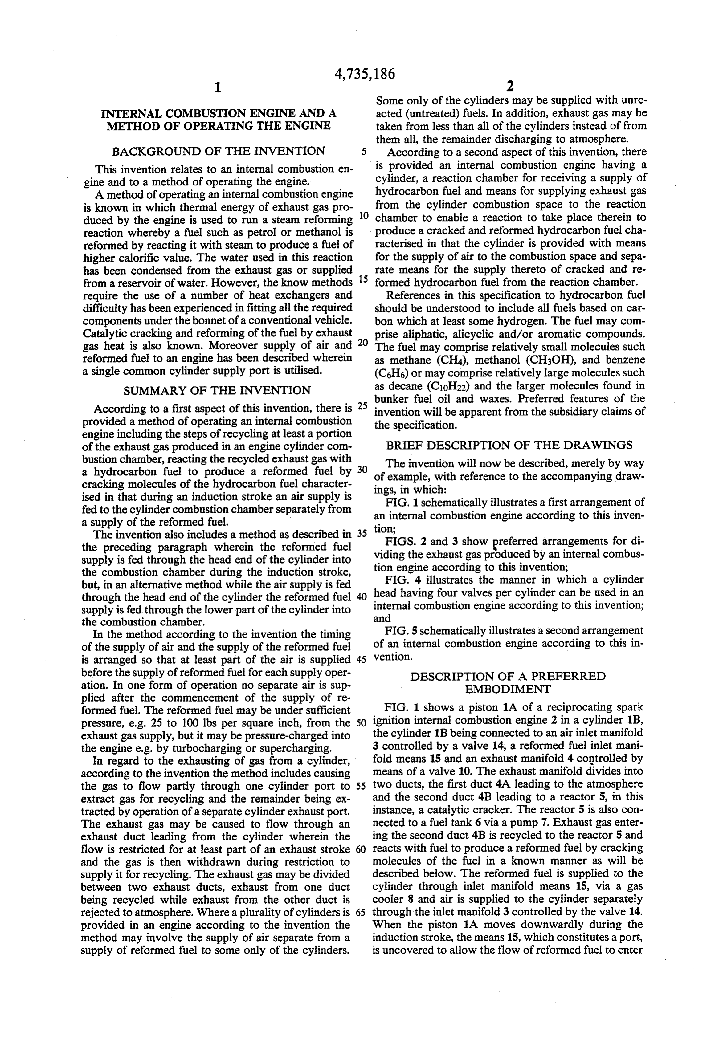
BACKGROUND OF THE INVENTION 5 According to a second aspect of this invention, there This invention relates to an internal combustion en is provided an internal combustion engine having a gine and to a method of operating the engine. cylinder, a reaction chamber for receiving a supply of A method of operating an internal combustion engine hydrocarbon fuel and means for supplying exhaust gas is known in which thermal energy of exhaust gas pro O from the cylinder combustion space to the reaction duced by the engine is used to run a steam reforming chamber to enable a reaction to take place therein to reaction whereby a fuel such as petrol or methanol is produce a cracked and reformed hydrocarbon fuel cha reformed by reacting it with steam to produce a fuel of racterised in that the cylinder is provided with means higher calorific value. The water used in this reaction for the supply of air to the combustion space and sepa has been condensed from the exhaust gas or supplied 15 rate means for the supply thereto of cracked and re from a reservoir of water. However, the know methods formed hydrocarbon fuel from the reaction chamber. require the use of a number of heat exchangers and References in this specification to hydrocarbon fuel difficulty has been experienced in fitting all the required should be understood to include all fuels based on car components under the bonnet of a conventional vehicle. bon which at least some hydrogen. The fuel may com Catalytic cracking and reforming of the fuel by exhaust prise aliphatic, alicyclic and/or aromatic compounds. gas heat is also known. Moreover supply of air and 20 The fuel may comprise relatively small molecules such reformed fuel to an engine has been described wherein as methane (CH4), methanol (CH3OH), and benzene a single common cylinder supply port is utilised. (C6H6) or may comprise relatively large molecules such SUMMARY OF THE INVENTION as decane (C10H22) and the larger molecules found in bunker fuel oil and waxes. Preferred features of the
According to a first aspect of this invention, there is 25 invention will be apparent from the subsidiary claims of provided a method of operating an internal combustion the specification.
engine including the steps of recycling at least a portion of the exhaust gas produced in an engine cylinder com BRIEF DESCRIPTION OF THE DRAWINGS bustion chamber, reacting the recycled exhaust gas with a hydrocarbon fuel to produce a reformed fuel by 30 ofThe invention will now be described, merely by way example, with reference to the accompanying draw cracking molecules of the hydrocarbon fuel character ings, in which:
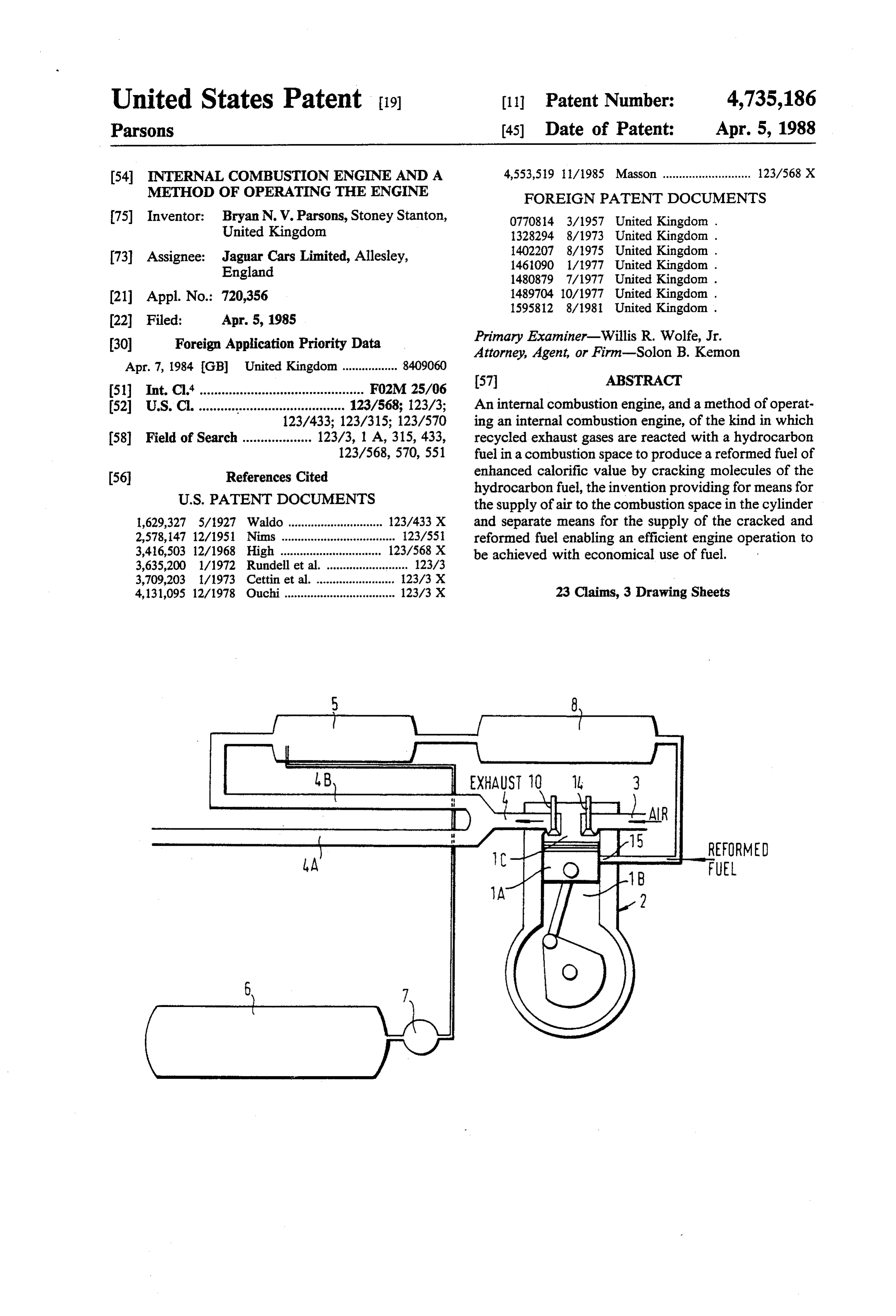
ised in that during an induction stroke an air supply is fed to the cylinder combustion chamber separately from anFIG. 1 schematically illustrates a first arrangement of internal combustion engine according to this inven a supply of the reformed fuel. tion;
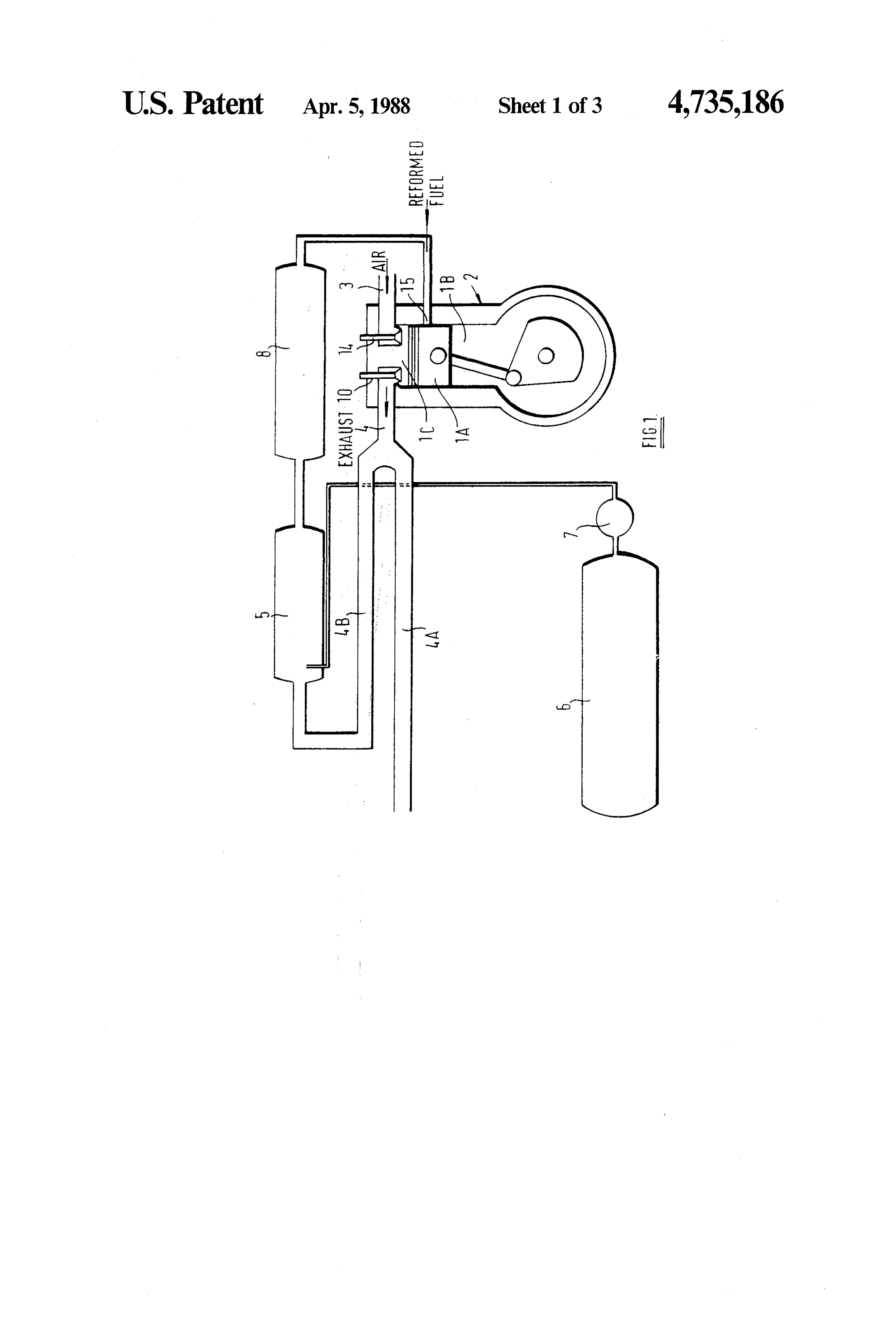
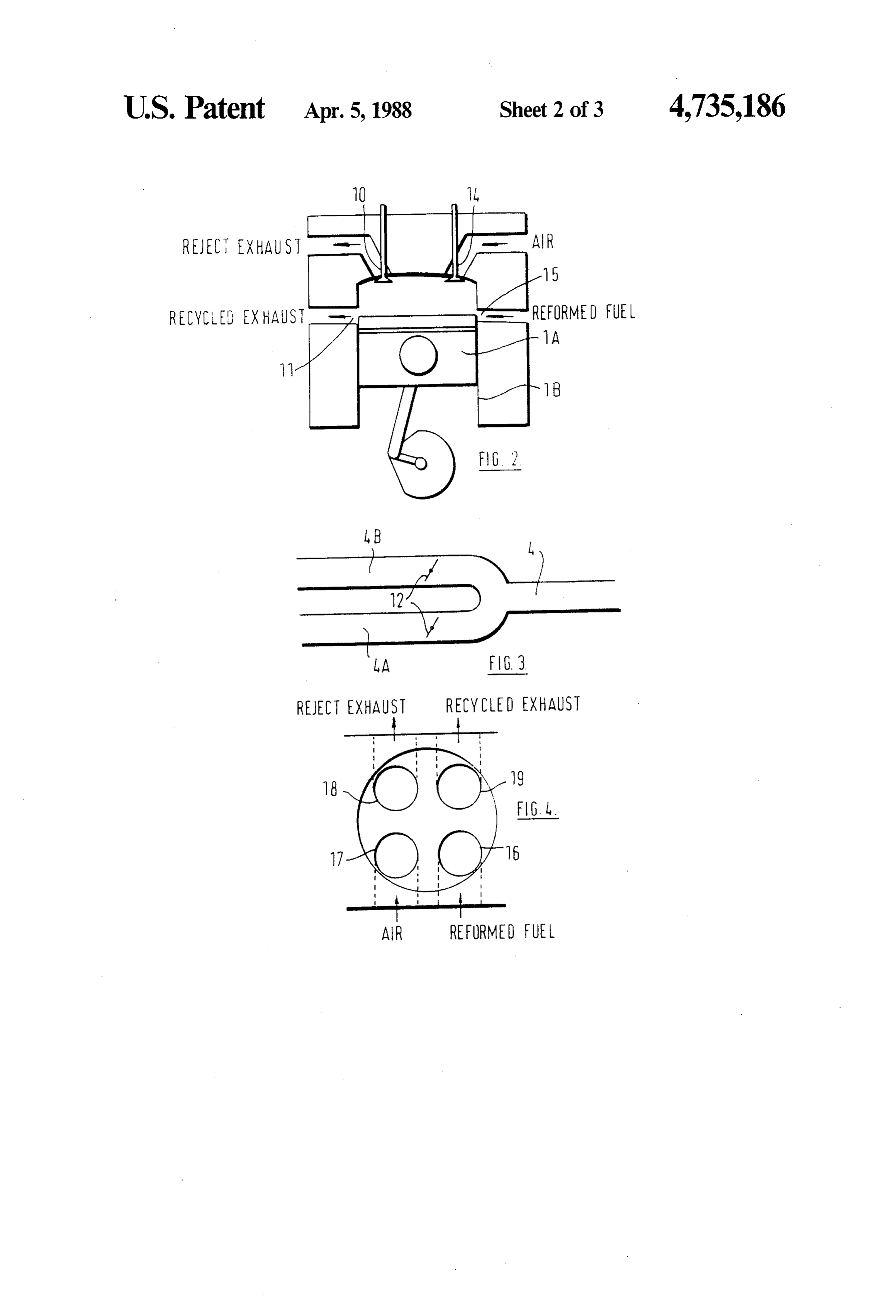
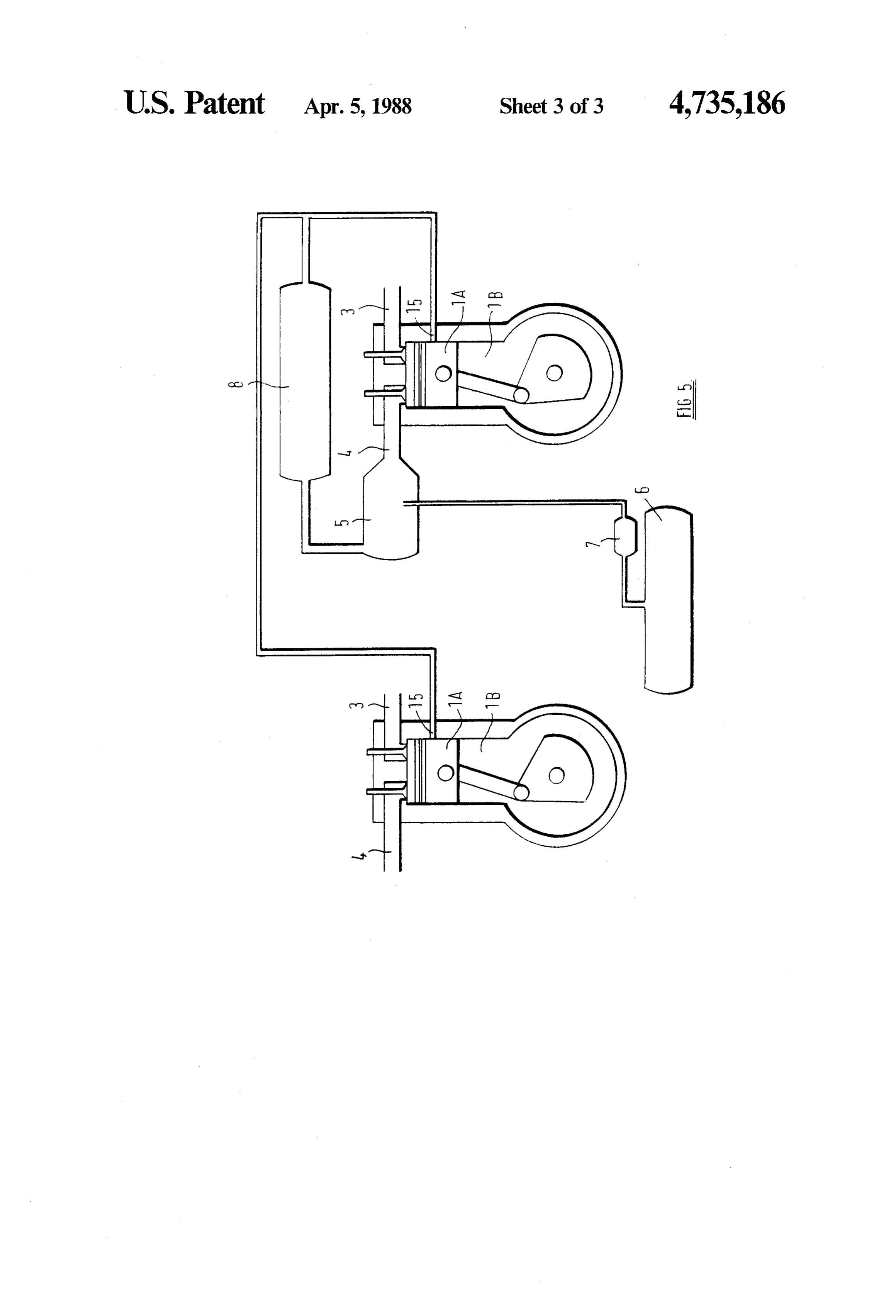
The invention also includes a method as described in 35 the preceding paragraph wherein the reformed fuel viding FIGS. 2 and 3 show preferred arrangements for di supply is fed through the head end of the cylinder into the exhaust gas produced by an internal combus the combustion chamber during the induction stroke, tionFIG. engine according to this invention; 4 illustrates the manner in which a cylinder but, in an alternative method while the air supply is fed head having four valves per cylinder can be used in an through the head end of the cylinder the reformed fuel internal combustion engine according to this invention; supply is fed through the lower part of the cylinder into and the combustion chamber.
In the method according to the invention the timing FIG. 5 schematically illustrates a second arrangement of the supply of air and the supply of the reformed fuel of an internal combustion engine according to this in is arranged so that at least part of the air is supplied 45 vention.
before the supply of reformed fuel for each supply oper DESCRIPTION OF A PREFERRED ation. In one form of operation no separate air is sup EMBODIMENT plied after the commencement of the supply of re FIG. 1 shows a piston 1A of a reciprocating spark formed fuel. The reformed fuel may be under sufficient pressure, e.g. 25 to 100 lbs per square inch, from the 50 ignition internal combustion engine 2 in a cylinder 1B, exhaust gas supply, but it may be pressure-charged into the cylinder 1B being connected to an air inlet manifold the engine e.g. by turbocharging or supercharging. 3 controlled by a valve 14, a reformed fuel inlet mani In regard to the exhausting of gas from a cylinder, fold means 15 and an exhaust manifold 4 controlled by according to the invention the method includes causing means of a valve 10. The exhaust manifold divides into the gas to flow partly through one cylinder port to 55 two ducts, the first duct 4A leading to the atmosphere extract gas for recycling and the remainder being ex and the second duct 4B leading to a reactor 5, in this tracted by operation of a separate cylinder exhaust port. instance, a catalytic cracker. The reactor 5 is also con The exhaust gas may be caused to flow through an nected to a fuel tank 6 via a pump 7. Exhaust gas enter exhaust duct leading from the cylinder wherein the ing the second duct 4B is recycled to the reactor 5 and flow is restricted for at least part of an exhaust stroke reacts with fuel to produce a reformed fuel by cracking and the gas is then withdrawn during restriction to molecules of the fuel in a known manner as will be supply it for recycling. The exhaust gas may be divided described below. The reformed fuel is supplied to the between two exhaust ducts, exhaust from one duct cylinder through inlet manifold means 15, via a gas being recycled while exhaust from the other duct is cooler 8 and air is supplied to the cylinder separately rejected to atmosphere. Where a plurality of cylinders is 65 through the inlet manifold 3 controlled by the valve 14. provided in an engine according to the invention the When the piston 1A moves downwardly during the method may involve the supply of air separate from a induction stroke, the means 15, which constitutes a port, supply of reformed fuel to some only of the cylinders. is uncovered to allow the flow of reformed fuel to enter
Page 6
the combustion space 1C, to mix with the air already more than one third of the exhaust gas, e.g., one half, is drawn in through opened valve 14, and subsequently to utilised to give an excess quantity to ensure an efficient be burnt as a mixture to drive the engine 2. reaction.
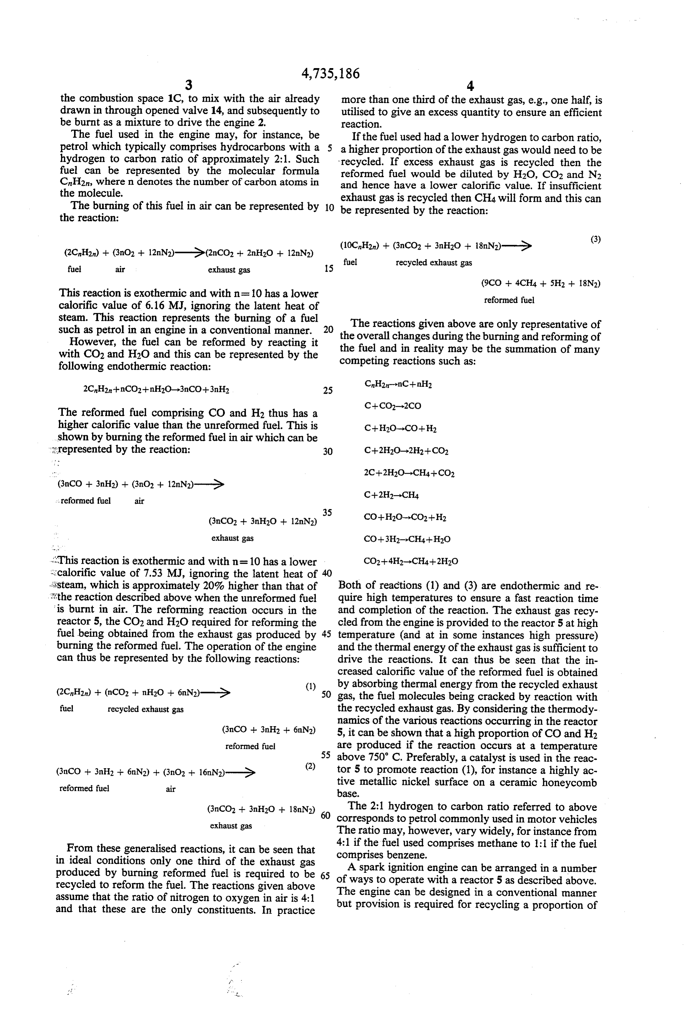
The fuel used in the engine may, for instance, be If the fuel used had a lower hydrogen to carbon ratio, petrol which typically comprises hydrocarbons with a 5 a higher proportion of the exhaust gas would need to be hydrogen to carbon ratio of approximately 2:1. Such recycled. If excess exhaust gas is recycled then the fuel can be represented by the molecular formula reformed fuel would be diluted by H2O, CO2 and N2 CnH2n, where n denotes the number of carbon atoms in and hence have a lower calorific value. If insufficient the molecule. exhaust gas is recycled then CH4 will form and this can The burning of this fuel in air can be represented by 10 be represented by the reaction:
the reaction:
(10CnH2n) + (3nCO2 + 3nH2O + 18nN)-G (3)
fuel recycled exhaust gas air exhaust gas
This reaction is exothermic and with n=10 has a lower reformed fuel calorific value of 6.16 MJ, ignoring the latent heat of steam. This reaction represents the burning of a fuel such as petrol in an engine in a conventional manner. 20 theThe reactions given above are only representative of However, the fuel can be reformed by reacting it the fuel andchanges overall during the burning and reforming of in reality may be the summation of many with CO2 and H2O and this can be represented by the competing reactions such as:
following endothermic reaction:
The reformed fuel comprising CO and H2 thus has a higher calorific value than the unreformed fuel. This is shown by burning the reformed fuel in air which can be 2 represented by the reaction: 30
, reformed fuel air
exhaust gas iThis reaction is exothermic and with n=10 has a lower scalorific value of 7.53 MJ, ignoring the latent heat of 40 sisteam, which is approximately 20% higher than that of Both of reactions (1) and (3) are endothermic and re the reaction described above when the unreformed fuel quire high temperatures to ensure a fast reaction time is burnt in air. The reforming reaction occurs in the and completion of the reaction. The exhaust gas recy reactor 5, the CO2 and H2O required for reforming the cled from the engine is provided to the reactor 5 at high fuel being obtained from the exhaust gas produced by 45 temperature (and at in some instances high pressure) burning the reformed fuel. The operation of the engine and the thermal energy of the exhaust gas is sufficient to can thus be represented by the following reactions: drive the reactions. It can thus be seen that the in creased calorific value of the reformed fuel is obtained (1) by absorbing thermal energy from the recycled exhaust (2CH2) + (ncO2 + nH2O + 6nN2)-Ge. 50 gas, the fuel molecules being cracked by reaction with fuel recycled exhaust gas the recycled exhaust gas. By considering the thermody
namics of the various reactions occurring in the reactor 5, it can be shown that a high proportion of CO and H2 reformed fuel are produced if the reaction occurs at a temperature 55 above 750 C. Preferably, a catalyst is used in the reac tor 5 to promote reaction (1), for instance a highly ac reformed fuel air tive metallic nickel surface on a ceramic honeycomb base.
(3nCO2 + 3nH2O -- 18nN2) The 2:1 hydrogen to carbon ratio referred to above exhaust gas corresponds to petrol commonly used in motor vehicles
The ratio may, however, vary widely, for instance from
From these generalised reactions, it can be seen that 4:1 if the fuel used comprises methane to 1:1 if the fuel in ideal conditions only one third of the exhaust gas comprises benzene.
produced by burning reformed fuel is required to be A spark ignition engine can be arranged in a number recycled to reform the fuel. The reactions given above of ways to operate with a reactor 5 as described above. assume that the ratio of nitrogen to oxygen in air is 4:1 The engine can be designed in a conventional manner and that these are the only constituents. In practice but provision is required for recycling a proportion of
Page 7
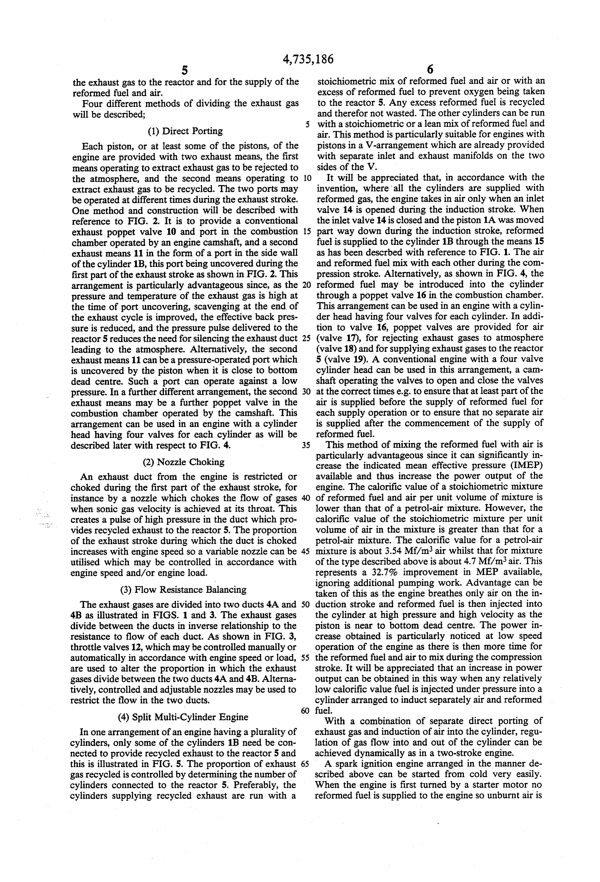
the exhaust gas to the reactor and for the supply of the stoichiometric mix of reformed fuel and air or with an reformed fuel and air. excess of reformed fuel to prevent oxygen being taken Four different methods of dividing the exhaust gas to the reactor 5. Any excess reformed fuel is recycled will be described; and therefor not wasted. The other cylinders can be run with a stoichiometric or a lean mix of reformed fuel and (1) Direct Porting air. This method is particularly suitable for engines with Each piston, or at least some of the pistons, of the pistons in a V-arrangement which are already provided engine are provided with two exhaust means, the first with separate inlet and exhaust manifolds on the two means operating to extract exhaust gas to be rejected to sides of the V.
the atmosphere, and the second means operating to 10 It will be appreciated that, in accordance with the extract exhaust gas to be recycled. The two ports may invention, where all the cylinders are supplied with be operated at different times during the exhaust stroke. reformed gas, the engine takes in air only when an inlet One method and construction will be described with valve 14 is opened during the induction stroke. When reference to FIG. 2. It is to provide a conventional the inlet valve 14 is closed and the piston 1A was moved exhaust poppet valve 10 and port in the combustion 15 part way down during the induction stroke, reformed chamber operated by an engine camshaft, and a second fuel is supplied to the cylinder 1B through the means 15 exhaust means 11 in the form of a port in the side wall as has been described with reference to FIG. 1. The air of the cylinder 1B, this port being uncovered during the and reformed fuel mix with each other during the com first part of the exhaust stroke as shown in FIG. 2. This pression stroke. Alternatively, as shown in FIG. 4, the arrangement is particularly advantageous since, as the 20 reformed fuel may be introduced into the cylinder pressure and temperature of the exhaust gas is high at through a poppet valve 16 in the combustion chamber. the time of port uncovering, scavenging at the end of This arrangement can be used in an engine with a cylin the exhaust cycle is improved, the effective back pres der head having four valves for each cylinder. In addi sure is reduced, and the pressure pulse delivered to the tion to valve 16, poppet valves are provided for air reactor 5 reduces the need for silencing the exhaust duct 25 (valve 17), for rejecting exhaust gases to atmosphere leading to the atmosphere. Alternatively, the second (valve 18) and for supplying exhaust gases to the reactor exhaust means 11 can be a pressure-operated port which 5 (valve 19). A conventional engine with a four valve is uncovered by the piston when it is close to bottom cylinder head can be used in this arrangement, a can dead centre. Such a port can operate against a low shaft operating the valves to open and close the valves pressure. In a further different arrangement, the second 30 at the correct times e.g. to ensure that at least part of the exhaust means may be a further poppet valve in the air is supplied before the supply of reformed fuel for combustion chamber operated by the camshaft. This each supply operation or to ensure that no separate air arrangement can be used in an engine with a cylinder is supplied after the commencement of the supply of head having four valves for each cylinder as will be reformed fuel.
described later with respect to FIG. 4. 35 This method of mixing the reformed fuel with air is particularly advantageous since it can significantly in (2) Nozzle Choking crease the indicated mean effective pressure (IMEP) An exhaust duct from the engine is restricted or available and thus increase the power output of the choked during the first part of the exhaust stroke, for engine. The calorific value of a stoichiometric mixture instance by a nozzle which chokes the flow of gases 40 of reformed fuel and air per unit volume of mixture is when sonic gas velocity is achieved at its throat. This lower than that of a petrol-air mixture. However, the creates a pulse of high pressure in the duct which pro calorific value of the stoichiometric mixture per unit vides recycled exhaust to the reactor 5. The proportion volume of air in the mixture is greater than that for a of the exhaust stroke during which the duct is choked petrol-air mixture. The calorific value for a petrol-air increases with engine speed so a variable nozzle can be 45 mixture is about 3.54 Mf/m3 air whilst that for mixture utilised which may be controlled in accordance with of the type described above is about 4.7 Mf/m3 air. This engine speed and/or engine load. represents a 32.7% improvement in MEP available, (3) Flow Resistance Balancing ignoring additional pumping work. Advantage can be taken of this as the engine breathes only air on the in
The exhaust gases are divided into two ducts 4A and 50 duction stroke and reformed fuel is then injected into 4B as illustrated in FIGS. 1 and 3. The exhaust gases the cylinder at high pressure and high velocity as the divide between the ducts in inverse relationship to the piston is near to bottom dead centre. The power in resistance to flow of each duct. As shown in FIG. 3, crease obtained is particularly noticed at low speed throttle valves 12, which may be controlled manually or operation of the engine as there is then more time for automatically in accordance with engine speed or load, 55 the reformed fuel and air to mix during the compression are used to alter the proportion in which the exhaust stroke. It will be appreciated that an increase in power gases divide between the two ducts 4A and 4.B. Alterna output can be obtained in this way when any relatively tively, controlled and adjustable nozzles may be used to low calorific value fuel is injected under pressure into a restrict the flow in the two ducts. cylinder arranged to induct separately air and reformed 60 fuel.
(4) Split Multi-Cylinder Engine With a combination of separate direct porting of In one arrangement of an engine having a plurality of exhaust gas and induction of air into the cylinder, regu cylinders, only some of the cylinders 1B need be con lation of gas flow into and out of the cylinder can be nected to provide recycled exhaust to the reactor 5 and achieved dynamically as in a two-stroke engine. this is illustrated in FIG. 5. The proportion of exhaust 65 A spark ignition engine arranged in the manner de gas recycled is controlled by determining the number of scribed above can be started from cold very easily. cylinders connected to the reactor 5. Preferably, the When the engine is first turned by a starter motor no cylinders supplying recycled exhaust are run with a reformed fuel is supplied to the engine so unburnt air is
Page 8
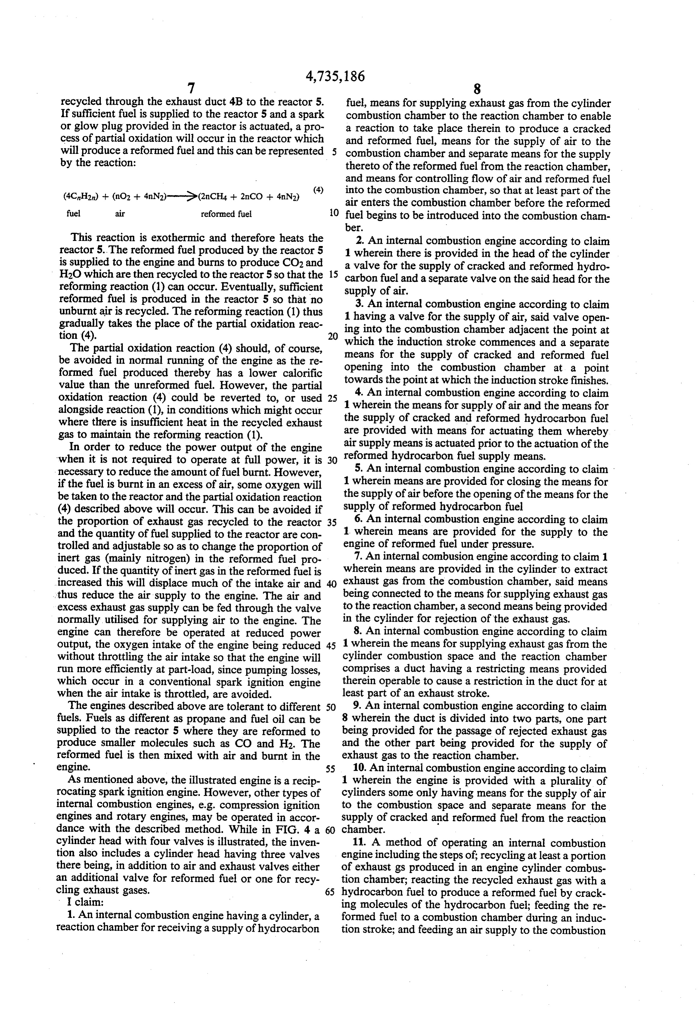
recycled through the exhaust duct 4B to the reactor 5. fuel, means for supplying exhaust gas from the cylinder If sufficient fuel is supplied to the reactor 5 and a spark combustion chamber to the reaction chamber to enable or glow plug provided in the reactor is actuated, a pro a reaction to take place therein to produce a cracked cess of partial oxidation will occur in the reactor which and reformed fuel, means for the supply of air to the will produce a reformed fuel and this can be represented combustion chamber and separate means for the supply by the reaction: thereto of the reformed fuel from the reaction chamber, and means for controlling flow of air and reformed fuel
4. into the combustion chamber, so that at least part of the air enters the combustion chamber before the reformed fuel air reformed fuel 10 fuel begins to be introduced into the combustion cham ber.
This reaction is exothermic and therefore heats the 2. An internal combustion engine according to claim reactor 5. The reformed fuel produced by the reactor 5 1 wherein there is provided in the head of the cylinder is supplied to the engine and burns to produce CO2 and a valve for the supply of cracked and reformed hydro H2O which are then recycled to the reactor 5 so that the 15 reforming reaction (1) can occur. Eventually, sufficient carbon fuel and a separate valve on the said head for the supply of air.
reformed fuel is produced in the reactor 5 so that no 3. An internal combustion engine according to claim unburnt air is recycled. The reforming reaction (1) thus 1 having a valve for the supply of air, said valve open gradually takes the place of the partial oxidation reac ing into the combustion chamber adjacent the point at
The partial oxidation reaction (4) should, of course, means for the supplystroke which the induction commences and a separate of cracked and reformed fuel be avoided in normal running of the engine as the re opening into the combustion chamber at a point formed fuel produced thereby has a lower calorific towards the point at which the induction stroke finishes. value than the unreformed fuel. However, the partial 4. An internal combustion engine according to claim oxidation reaction (4) could be reverted to, or used 25 1 wherein the means for supply of air and the means for alongside reaction (1), in conditions which might occur the supply of cracked and reformed hydrocarbon fuel where there is insufficient heat in the recycled exhaust gas to maintain the reforming reaction (1). are provided with means for actuating them whereby In order to reduce the power output of the engine air supply means is actuated prior to the actuation of the when it is not required to operate at full power, it is 30 reformed hydrocarbon fuel supply means. necessary to reduce the amount of fuel burnt. However, 5. An internal combustion engine according to claim if the fuel is burnt in an excess of air, some oxygen will 1 wherein means are provided for closing the means for be taken to the reactor and the partial oxidation reaction the supply of air before the opening of the means for the (4) described above will occur. This can be avoided if supply of reformed hydrocarbon fuel the proportion of exhaust gas recycled to the reactor 35 6. An internal combustion engine according to claim and the quantity of fuel supplied to the reactor are con 1 wherein means are provided for the supply to the trolled and adjustable so as to change the proportion of engine of reformed fuel under pressure. inert gas (mainly nitrogen) in the reformed fuel pro 7. An internal combusion engine according to claim 1 duced. If the quantity of inert gas in the reformed fuel is wherein means are provided in the cylinder to extract increased this will displace much of the intake air and exhaust gas from the combustion chamber, said means thus reduce the air supply to the engine. The air and being connected to the means for supplying exhaust gas excess exhaust gas supply can be fed through the valve to the reaction chamber, a second means being provided normally utilised for supplying air to the engine. The in the cylinder for rejection of the exhaust gas. engine can therefore be operated at reduced power 8. An internal combustion engine according to claim output, the oxygen intake of the engine being reduced 45 1 wherein the means for supplying exhaust gas from the without throttling the air intake so that the engine will cylinder combustion space and the reaction chamber run more efficiently at part-load, since pumping losses, comprises a duct having a restricting means provided which occur in a conventional spark ignition engine therein operable to cause a restriction in the duct for at when the air intake is throttled, are avoided. least part of an exhaust stroke. The engines described above are tolerant to different 50 9. An internal combustion engine according to claim fuels. Fuels as different as propane and fuel oil can be 8 wherein the duct is divided into two parts, one part supplied to the reactor 5 where they are reformed to being provided for the passage of rejected exhaust gas produce smaller molecules such as CO and H2. The and the other part being provided for the supply of reformed fuel is then mixed with air and burnt in the exhaust gas to the reaction chamber. engine. 55 10. An internal combustion engine according to claim As mentioned above, the illustrated engine is a recip 1 wherein the engine is provided with a plurality of rocating spark ignition engine. However, other types of cylinders some only having means for the supply of air internal combustion engines, e.g. compression ignition to the combustion space and separate means for the engines and rotary engines, may be operated in accor supply of cracked and reformed fuel from the reaction dance with the described method. While in FIG. 4 a. chamber.
cylinder head with four valves is illustrated, the inven 11. A method of operating an internal combustion tion also includes a cylinder head having three valves engine including the steps of; recycling at least a portion there being, in addition to air and exhaust valves either of exhaust gs produced in an engine cylinder combus an additional valve for reformed fuel or one for recy tion chamber; reacting the recycled exhaust gas with a cling exhaust gases. 65 hydrocarbon fuel to produce a reformed fuel by crack I claim: ing molecules of the hydrocarbon fuel; feeding the re 1. An internal combustion engine having a cylinder, a formed fuel to a combustion chamber during an induc reaction chamber for receiving a supply of hydrocarbon tion stroke; and feeding an air supply to the combustion
Page 9
chamber; the reformed fuel and air being fed to the and withdrawing the exhaust gas during restriction to combustion chamber separately, and being timed to supply it for recycling.
occur so that at least part of the air is supplied before 18. A method according to claim 11 wherein the introduction of the reformed fuel begins, for each sup exhaust gas flow is divided between two exhaust ducts, ply operation. exhaust from one duct being recycled while exhaust gas 12. A method according to claim 11 wherein the air from the other duct is rejected.
supply and the reformed fuel supply are fed through the 19. A method of operating an internal combustion head end of the cylinder into the combustion chamber. engine according to claim 11 wherein less than all of the 13. A method according to claim 11 wherein the air cylinders supply exhaust gas to produce a reformed supply is introduced into the combustion chamber at a O fuel.
point adjacent the beginning of the induction stroke and 20. A method according to claim 11 wherein the the reformed fule supply is introduced into the combus engine is provided with a plurality of cylinders some tion chamber at a point towards the end of the induction only of the cylinders having a supply of air separate stroke.
14. A method according to claim 11 wherein no sepa 15 from a supply of reformed fuel. rate air is supplied after the commencement of the sup engineAaccording 21. method of operating an internal combustion to claim 20 wherein some of the cylin ply of reformed fuel. ders are supplied with an untreated hydrocarbon fuel. 15. A method according to claim 11 wherein the 22. A method of operating an internal combustion reformed fuel is pressure charged into the engine.
16. A method acccording to claim 11 wherein the 20 engine according to claim 11 wherein the respective exhaust gas flows partly through one cylinder port to amounts of hydrocarbon fuel and recycled exhaust gas extract gas for recycling and the remainder is extracted utilised to produce a reformed fuel are controlled and by operation of a separate cylinder exhaust port. adjustable.
17. A method according to claim 11 wherein the 23. A method of operating an internal combustion exhaust gas is caused to flow through an exhaust duct 25 engine according to claim 22 wherein the adjustment leading from the cyclinder, the flow in the said duct operates to reduce thes powers output.
being restricted for at least part of the exhaust stroke
Provenance
- Collection
- Cited prior art
- Original PDF
- patentimages.storage.googleapis.com →
- Filed
- 1985-04-05
- Pages
- 9
- Method
- pdftotext (the PDF's own text layer) + pdftoppm 300dpi page scans
- Source
- Google Patents bibliographic record
- Granted
- 1988-04-05
- Inventors
- Bryan N. V. Parsons; Jaguar Cars Ltd
- Transcribed from
- patentimages.storage.googleapis.com →