patent · US1210897
Gas-engine.
2 January 1917
Page 1
Drawing sheet — no readable text.
Page 2
Drawing sheet — no readable text.
Page 3
Drawing sheet — no readable text.
Page 4
Drawing sheet — no readable text.
Page 5
TED STATES PATENT OFFICE.
ARTHUR BENJ. BROWNE, OF DENVER, COLORADO.
Specification of Letters Patent. . Patented Jan. 2, 1917.
Application filed July 9, 1910, Serial No. 571,247. Renewed March 12, 1915. serial No. 13,967. To all whom it may concern: loading Valve is also provided so that if the compression exceeds a certain predetermined
Be it known that I, ARTHUR B. BROWNE, amount, a portion of the air in the cylinder a citizen of the United States, and resident is discharged to the atmosphere. In this 60 of Denver, in the county of Denver, State of Way after the desired compression pressure Colorado, have invented certain new and useful Improvements in Gas-Engines, of is reached, further work of compression and which the following is a specification. losses incidental thereto are avoided. Pro vision is made for placing the fuel under
My invention relates to an improved gas positive engine of the constant-pressure-type, of pressed pressure charge for its delivery to the com as it reinters the cylinder.
10 high thermal efficiency. The mechanism for controlling the re-admis The invention has been developed in con crete form so that it operates on a cycle sion of the charge to the cylinder is designed to permit an operative effect comparable to comparable to an ordinary two-stroke cycle. the cut-off in a steam engine and this mech 70 IBy using this cycle the greatest efficiency anism 15 will probably be obtained because every sec time designed in a preferred form is at the same ond stroke of a working piston is a power to permit the engine to run stroke; but the principles of the invention In equally well in either direction of rotation. may be adapted to other cycles. the specific embodiment of the invention, The following are some of the principal these results are obtained by the introduc 75 20 characteristics of an engine embodying my tion of a link motion to control the inlet, or invention: A body of air at suitable pres return The valve.
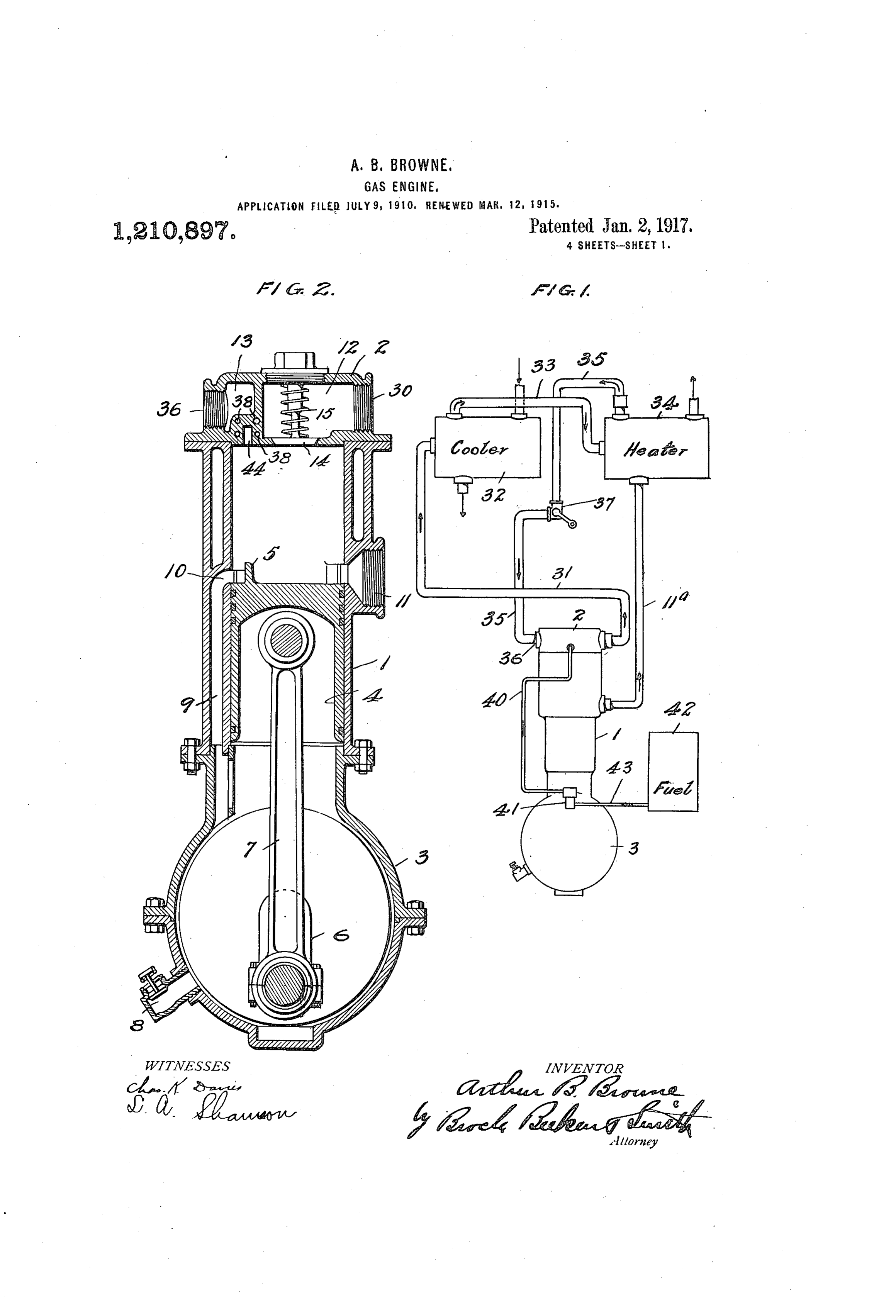
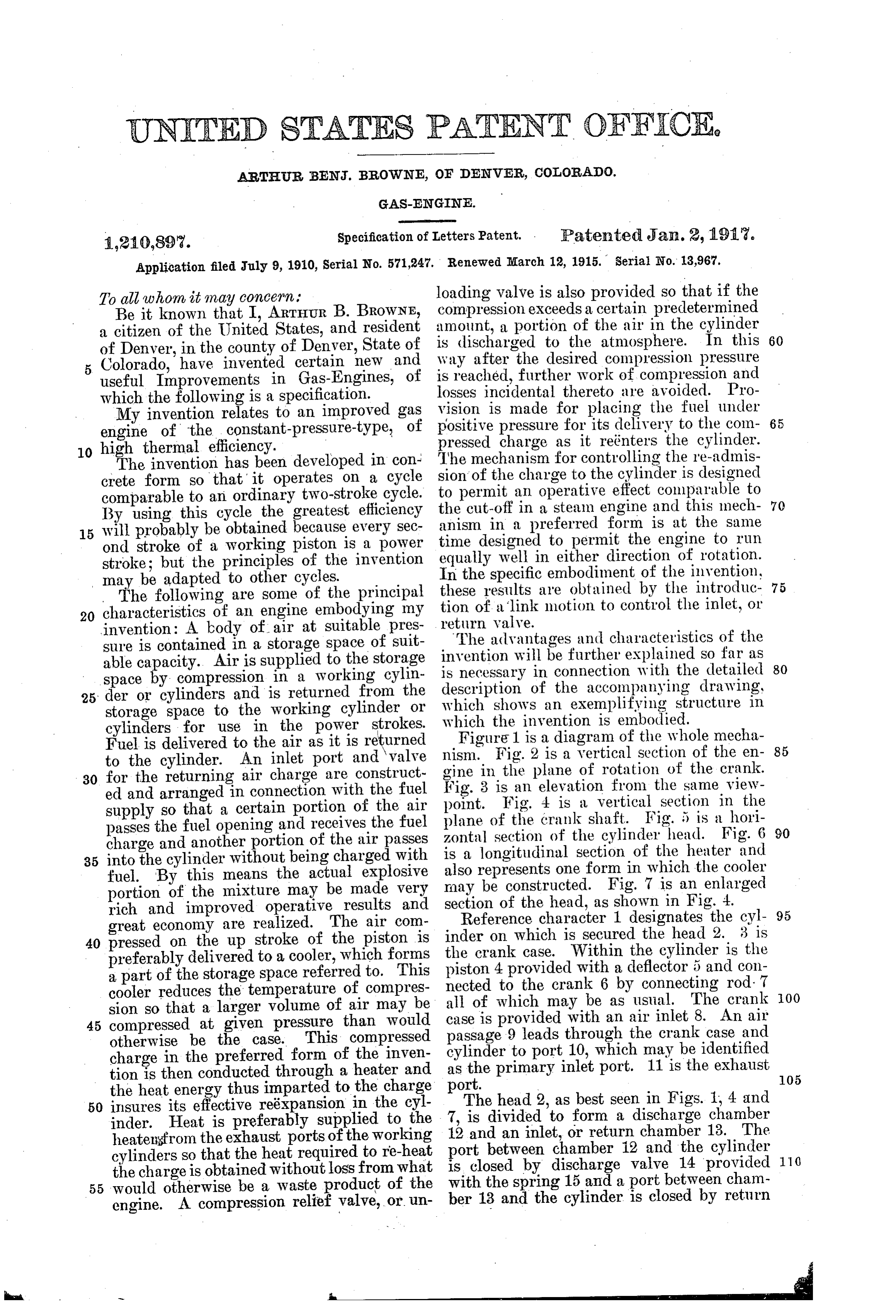
advantages and characteristics of the sure is contained in a storage space of suit invention will be further able capacity. Air is supplied to the storage is necessary in connectionexplained so far as with the detailed 80 space by compression in a working cylin description of the accompanying drawing, 25 der or cylinders and is returned from the which shows an exemplifying storage space to the working cylinder or which the invention is embodied. structure in cylinders for use in the power strokes. Figure 1 is a diagram of the whole mecha Fuel is delivered to the air as it is returned to the cylinder. An inlet port and valve gine nism. Fig. 2 is a vertical section of the en 85 30 for the returning air charge are construct in the plane of rotation of the crank. ed and arranged in connection with the fuel point. isFig.
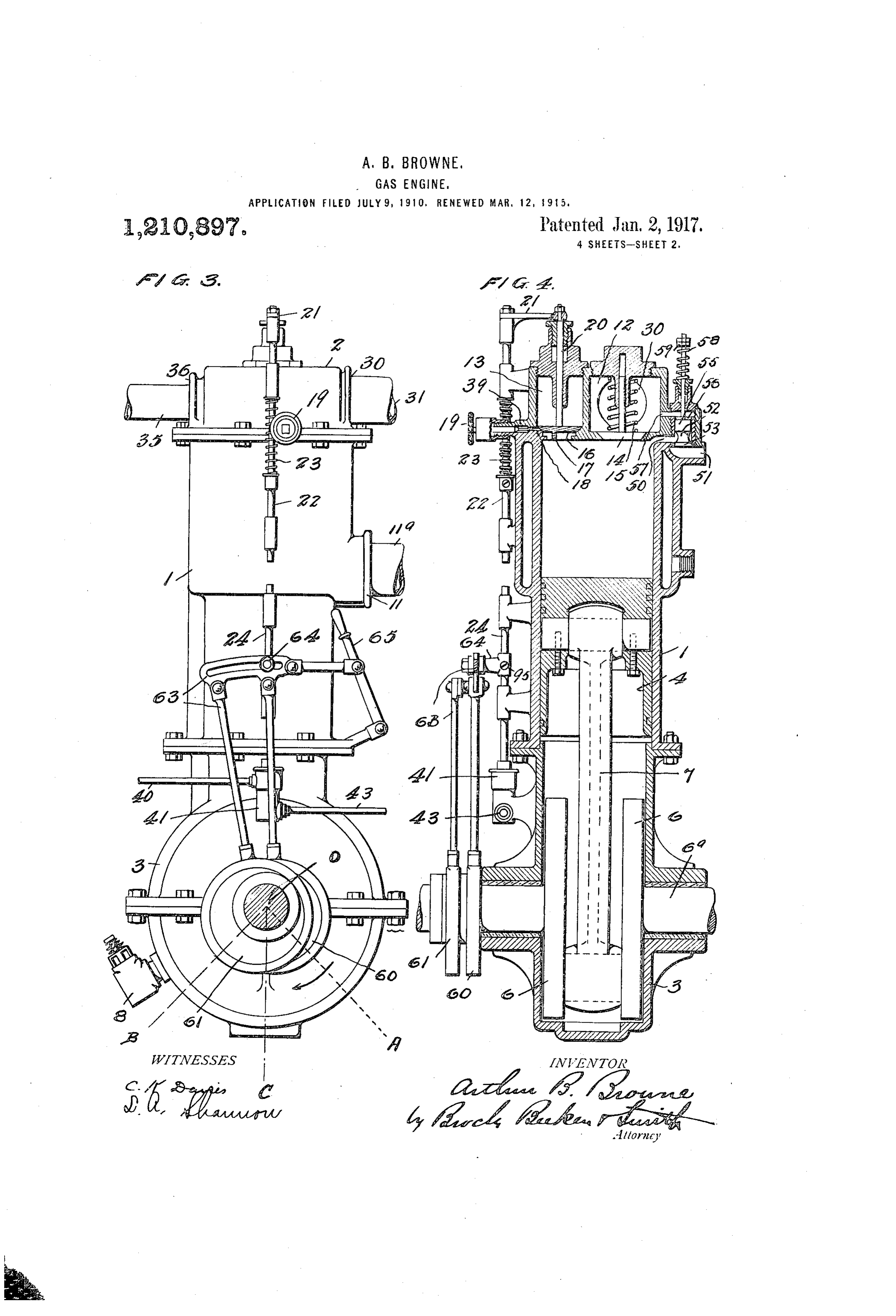
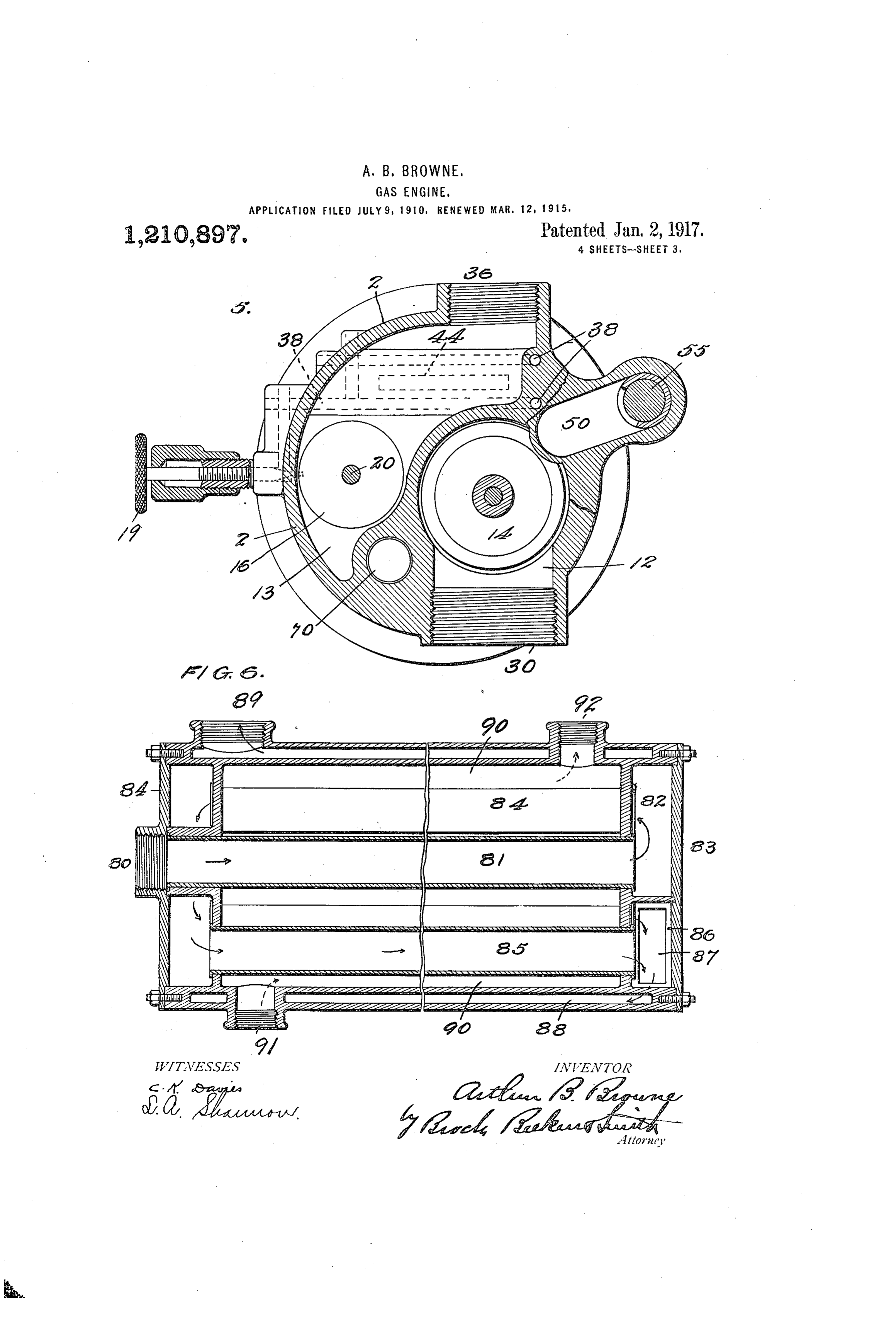
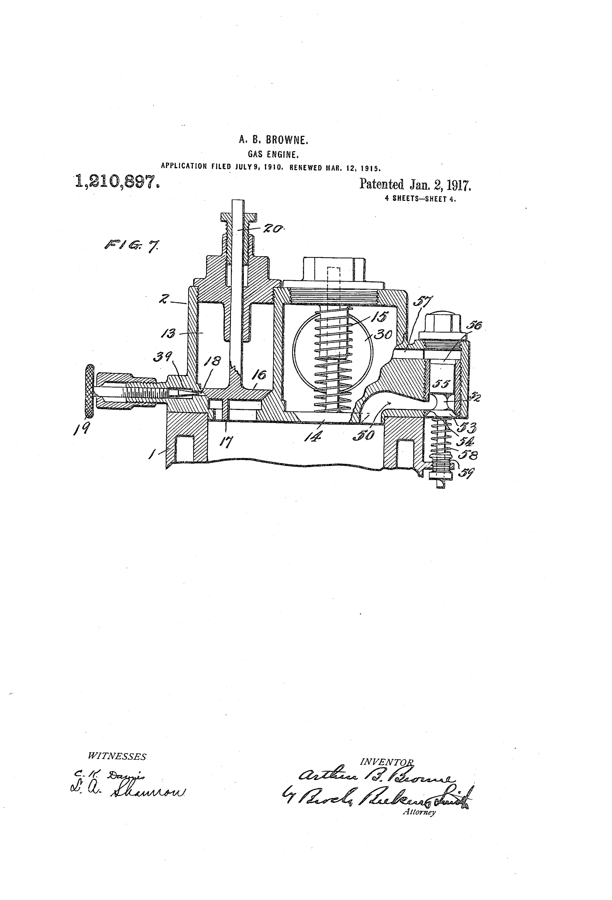
Fig. 3 an elevation from the same view 4 is a vertical section in the supply so that a certain portion of the air plane of the crank passes the fuel opening and receives the fuel zontal section of theshaft. Fig. 5 is a hori cylinder head. Fig. 6 90 charge and another portion of the air passes is a longitudinal section of the heater and 35 into the cylinder without being charged with fuel. By this means the actual explosive also represents one form in which the cooler portion of the mixture may be made very may be constructed. Fig. 7 is an enlarged rich and improved operative results and section of the head, as shown in Fig. 4. Reference character 1 designates the cyl 95 great economy are realized. The air com inder on which is secured the head 2. 3 is 40 pressed on the up stroke of the piston is the crank case. Within the cylinder is the preferably delivered to a cooler, which forms piston 4 provided a part of the storage space referred to. This nected to the crank with a deflector 5 and con cooler reduces the temperature of compres all of which may be6 asbyusual. connecting rod. 7 OO sion so that a larger volume of air may be case is provided with an air inlet The 8. crank
An air 45 compressed at given pressure than Would otherwise be the case. This compressed passage 9 leads through the crank case and charge in the preferred form of the inven cylinder to port 10, which may be identified tion is then conducted through a heater and as the primary inlet port. 11 is the exhaust 105 the heat energy thus imparted to the charge port. The head 2, as best seen in Figs. 1, 4 and 50 insures its effective reéxpansion in the cyl inder. Heat is preferably supplied to the 7,12 isanddivided to form a discharge chamber an inlet, or return chamber 13. The heatensfrom the exhaust ports of the working port between chamber 12 and the cylinder 110 cylinders so that the heatrequired to re-heat is closed by discharge valve 14 provided the charge is obtained without loss from what 55 would otherwise be a waste product of the with the spring 15 and a port between cham engine. A compression relief valve, or un ber 13 and the cylinder is closed by return
-- d
Page 6
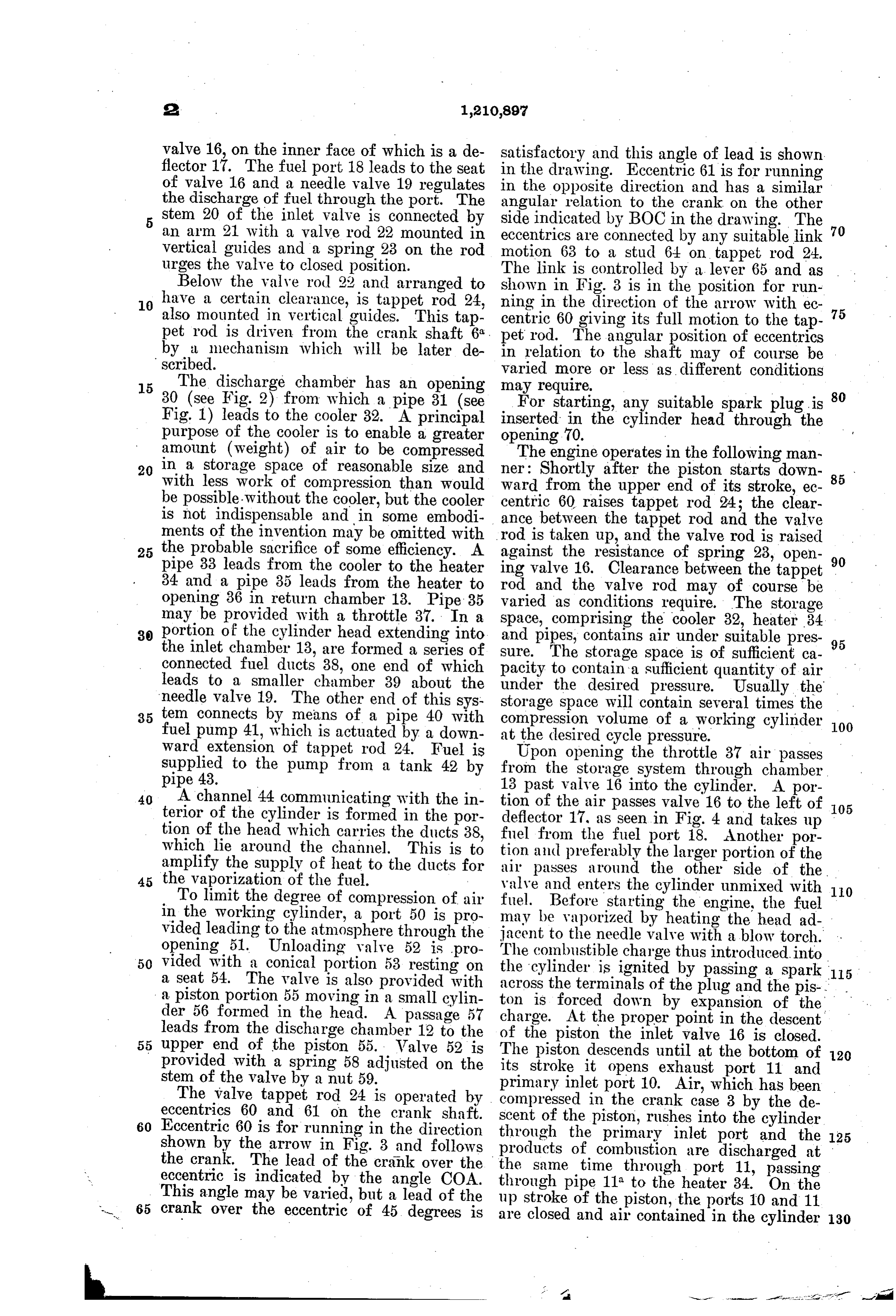
valve 16, on the inner face of which is a de satisfactory and this angle of lead is shown flector 17. The fuel port 18 leads to the seat in the drawing. Eccentric 61 is for running of valve 16 and a needle valve 19 regulates the discharge of fuel through the port. The in the opposite direction and has a similar angular relation to the crank on the other stem 20 of the inlet valve is connected by side indicated by BOC in the drawing. The an arm 21 with a valve rod 22 mounted in eccentrics are connected by any suitable link 70 vertical guides and a spring 23 on the rod motion 63 to a stud 64 on tappet rod 24. urges the valve to closed position. The link is controlled by a lever 65 and as Below the valve rod 22 and arranged to shown in Fig. 3 is in the position for run 0 have a certain clearance, is tappet rod 24, ning in the direction of the arrow with ec also mounted in vertical guides. This tap centric 60 giving its full motion to the tap 75 pet rod is driven from the crank shaft 6. pet rod. The angular position of eccentrics by a mechanism which will be later de in relation to the shaft may of course be scribed. varied more or less as different conditions 15 The discharge chamber has an opening may require.
30 (see Fig. 2) from which a pipe 31 (see For starting, any suitable spark plug is 80 Fig. 1) leads to the cooler 32. A principal inserted in the cylinder head through the purpose of the cooler is to enable a greater opening 70.
amount (weight) of air to be compressed The engine operates in the following man 20 in a storage space of reasonable size and ner: Shortly after the piston starts down with less work of compression than would ward from the upper end of its stroke, ec 85 be possible. Without the cooler, but the cooler centric 60 raises tappet rod 24; the clear is not indispensable and in some embodi ance between the tappet rod and the valve ments of the invention may be omitted with rod is taken up, and the valve rod is raised 25 the probable sacrifice of some efficiency. A against the resistance of spring 23, open pipe 33 leads from the cooler to the heater ing valve 16. Clearance between the tappet 90 34 and a pipe 35 leads from the heater to rod and the valve rod may of course be opening 36 in return chamber 13. Pipe 35 varied as conditions require. The storage may be provided with a throttle 37. In a space, comprising the cooler 32, heater 34 30 portion of the cylinder head extending into and pipes, contains air under suitable pres the inlet chamber 13, are formed a series of sure. The storage space is of sufficient ca 95 connected fuel ducts 38, one end of which pacity to contain a sufficient quantity of air leads to a smaller chamber 39 about the under the desired pressure. Usually the needle valve 19. The other end of this sys storage space will contain several times the 35 tem connects by means of a pipe 40 with compression volume of a working cylinder fuel pump 41, which is actuated by a down at the desired cycle pressure. 100 Ward extension of tappet rod 24. Fuel is Upon opening the throttle 37 air passes supplied to the pump from a tank 42 by from the storage system through chamber pipe 43. 13 past valve 16 into the cylinder. A por 40 A channel 44 communicating with the in tion of the air passes valve 16 to the left of terior of the cylinder is formed in the por deflector 17, as seen in Fig. 4 and takes up 105 tion of the head which carries the ducts 38, fuel from the fuel port 18. Another por which lie around the channel. This is to tion and amplify the supply of heat to the ducts for air passespreferably around the larger portion of the the other side of the 45 the vaporization of the fuel.
To limit the degree of compression of air fuel. Before startingcylinder valve and enters the the unmixed with 10 engine, the fuel in the working cylinder, a port 50 is pro may be vaporized by heating the head ad vided leading to the atmosphere through the jacent to the needle valve with a blow torch. opening 51. Unloading valve 52 is pro The combustible charge thus introduced into 50 vided with a conical portion 53 resting on the cylinder is ignited by passing a spark 115 a seat 54. The valve is also provided with across the terminals of the plug and the pis a pistonportion 55 moving in a small cylin ton is forced down by expansion of the - der 56 formed in the head. A passage 57 charge. At the properpoint in the descent leads from the discharge chamber 12 to the of the piston the inlet valve 16 is closed. 55 upper end of the piston 55. Walve 52 is The piston descends until at the bottom of 120 provided with a spring 58 adjusted on the its stroke it opens exhaust port 11 and stem of the valve by a nut 59.
The valve tappet rod 24 is operated by primary inlet port 10. Air, which has been eccentrics 60 and 61 on the crank shaft. scent of the in compressed the crank case 3 by the de piston, rushes into the cylinder 60 Eccentric 60 is for running in the direction through the primary inlet port and the 125 shown by the arrow in Fig. 3 and follows the crank. The lead of the crank over the the same oftime products combustion are discharged at eccentric is indicated by the angle COA. through pipe 11 through to the port 11, passing heater 34. On the
This angle may be varied, but a lead 65 crank over the eccentric of 45 degrees is of the up stroke of the piston, the ports 10 and 11 are closed and air contained in the cylinder 130
Page 7
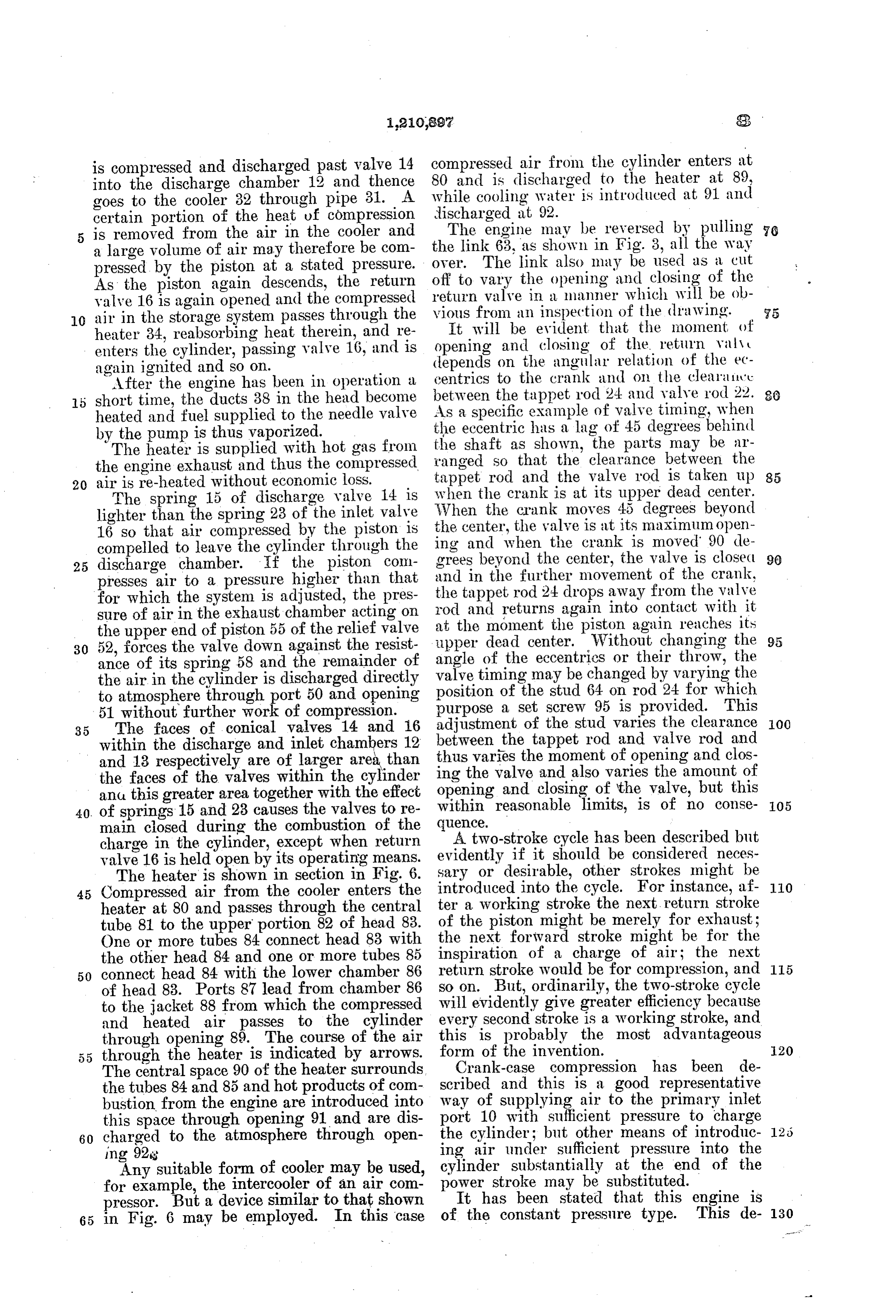
is compressed and discharged past valve 14 compressed air from the cylinder enters at into the discharge chamber 12 and thence 80 and is discharged to the heater at 89, goes to the cooler 32 through pipe 31. A while cooling water is introduced at 91 and certain portion of the heat of compression discharged at 92. - is removed from the air in the cooler and The engine may be reversed by pulling 76 a large volume of air may therefore be com the link 63, as shown in Fig. 3, all the way pressed by the piston at a stated pressure. off over. The link also may be used as a cut As the piston again descends, the return return to vary the opening and closing of the valve 16 is again opened and the compressed vious from valve in a manner which will be ob 10 air in the storage system passes through the an inspection of the drawing. S5 heater 34, reabsorbing heat therein, and re opening and evident
It will be that the moment of enters the cylinder, passing valve 16, and is depends on the angularof relation closing the return valv of the ec again ignited and so on.
After the engine has been in operation a centrics to the crank and on the clearair'e 80 short time, the ducts 38 in the head become between the tappet rod 24 and valve rod 22. heated and fuel supplied to the needle valve As a specific example of valve timing, when the eccentric has a lag of 45 degrees behind by the pump is thus vaporized. the shaft as shown, the parts may be ar The heater is supplied with hot gas from ranged so that the clearance between the the engine exhaust and thus the compressed tappet rod and the valve rod is taken up 85 20 air is re-heated without economic loss.
The spring 15 of discharge valve 14 is When when the crank is at its upper dead center. lighter than the spring 23 of the inlet valve the crank moves 45 degrees beyond 16 so that air compressed by the piston is ing the center, the valve is at its maximum open compelled to leave the cylinder through the and when the crank is moved 90 de 25 discharge chamber. If the piston com grees beyond the center, the valve is closed 90 presses air to a pressure higher than that and in the further movement of the crank, the tappet rod 24 drops away from the valve for which the system is adjusted, the pres rod sure of air in the exhaust chamber acting on at theandmoment returns again into contact with it the piston again reaches its the upper end of piston 55 of the relief valve 30 52, forces the valve down against the resist upper dead center. Without changing the 95 ance of its spring 58 and the remainder of angle timingof the eccentries or their throw, the the air in the cylinder is discharged directly valve position of may be changed by varying the the stud 64 on rod 24 for which to atmosphere through port 50 and opening 51 without further work of compression. purpose a set screw 95 is provided. This 35 The faces of conical valves 14 and 16 adjustment of the stud varies the clearance OO within the discharge and inlet chambers 12 thusbetween the tappet rod and valve rod and and 13 respectively are of larger area than ing the varies the moment of opening and clos the faces of the valves within the cylinder valve and also varies the amount of ana this greater area together with the effect opening within and closing of the valve, but this reasonable limits, is of no conse 05 40. of springs 15 and 23 causes the valves to re main closed during the combustion of the quence.
charge in the cylinder, except when return A two-stroke cycle has been described but valve 16 is held open by its operating means. evidently if it should be considered neces The heater is shown in section in Fig. 6. sary or desirable, other strokes might be O 45 Compressed air from the cooler enters the introduced into the cycle. For instance, af heater at 80 and passes through the central ter a Working stroke the next return stroke tube 81 to the upper portion 82 of head 83. of the piston might be merely for exhaust: One or more tubes 84 connect head 83 with the next forward stroke might be for the the other head 84 and one or more tubes 85 inspiration of a charge of air; the next 50 connect head 84 with the lower chamber 86 return stroke would be for compression, and 115 of head 83. Ports 87 lead from chamber 86 so on. But, ordinarily, the two-stroke cycle to the jacket 88 from which the compressed will evidently give greater efficiency because and heated air passes to the cylinder every second stroke is a working stroke, and through opening 89. The course of the air this is probably the most advantageous through the heater is indicated by arrows. form of the invention. 20 The central space 90 of the heater surrounds Crank-case compression has been de the tubes 84 and 85 and hot products of com scribed and this is a good representative bustion from the engine are introduced into way of supplying air to the primary inlet this space through opening 91 and are dis port 10 with sufficient pressure to charge 60 charged to the atmosphere through open the cylinder; but other means of introduc 125 ing 928 ing air under sufficient pressure into the Any suitable form of cooler may be used, cylinder substantially at the end of the for example, the intercooler of an air com power stroke may be substituted. pressor. But a device similar to that shown It has been stated that this engine is 65 in Fig. 6 may be employed. In this case of the constant pressure type. This de- 130
Page 8
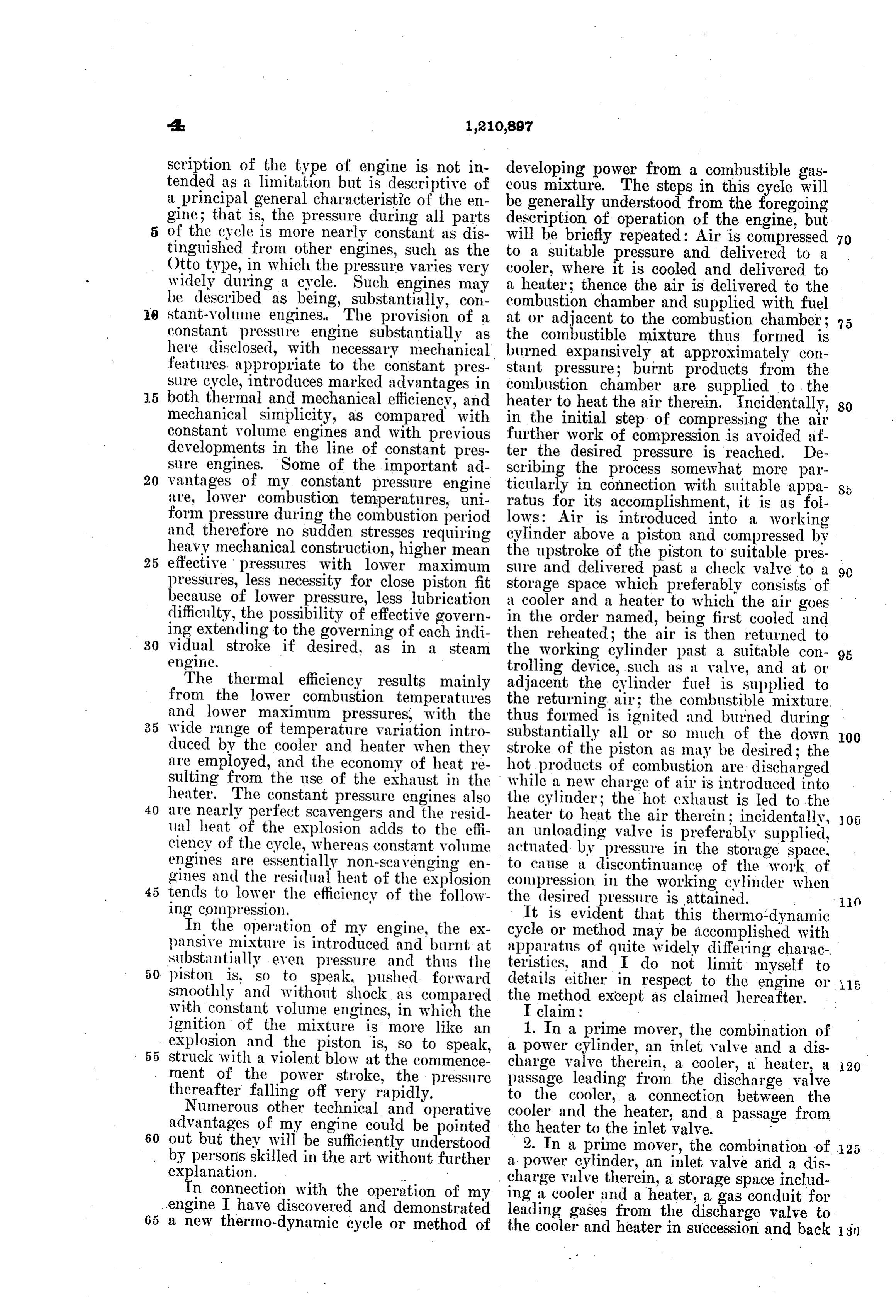
scription of the type of engine is not in developing power from a combustible gas tended as a limitation but is descriptive of eous mixture. The steps in this cycle will a principal general characteristic of the en gine; that is, the pressure during all parts be generally understood from the foregoing description of operation of the engine, but of the cycle is more nearly constant as dis will be briefly repeated: Air is compressed tinguished from other engines, such as the to a suitable pressure and delivered to a 70 Otto type, in which the pressure varies very widely during a cycle. Such engines may cooler, where it is cooled and delivered to be described as being, substantially, con combustionthence a heater; the air is delivered to the chamber and supplied with fuel 0 stant-volume engines. The provision of a at or adjacent to the combustion chamber; 75 constant pressure engine substantially as the combustible mixture thus formed is here disclosed, with necessary mechanical burned expansively at approximately con features appropriate to the constant pres stant pressure; burnt products from the sure cycle, introduces marked advantages in combustion chamber are supplied to the 5 both thermal and mechanical efficiency, and heater to heat the air therein. Incidentally, mechanical simplicity, as compared with in the initial step of compressing the air 80 constant volume engines and with previous further work of compression is avoided af developments in the line of constant pres ter the desired pressure is reached. De sure engines. Some of the important ad scribing the process somewhat more par 20 vantages of my constant pressure engine ticularly in connection with suitable appa are, lower combustion temperatures, uni ratus for its accomplishment, it is as fol form pressure during the combustion period lows: Air is introduced into a working and therefore no sudden stresses requiring cylinder above a piston and compressed by heavy mechanical construction, higher mean the upstroke of the piston to suitable pres 25 effective pressures with lower maximum pressures, less necessity for close piston fit sure and delivered past a check valve to a 90 storage space which preferably consists of because of lower pressure, less lubrication a cooler and a heater to which the air goes difficulty, the possibility of effective govern in the order named, being first cooled and ing extending to the governing of each indi then reheated; the air is then returned to 30 vidual stroke if desired, as in a steam engine. the working cylinder past a suitable con trolling device,
The thermal efficiency results mainly adjacent the cylinder such as a valve, and at or fuel is supplied to from the lower combustion temperatures the returning air; the combustible mixture. and lower maximum pressures, with the thus formed is ignited and burned during wide range of temperature variation intro substantially all or so much of the down 100 duced by the cooler and heater when they stroke of the piston as may be desired; the are employed, and the economy of heat re hot products of combustion are discharged sulting from the use of the exhaust in the while a new charge of air is introduced into heater. The constant pressure engines also the cylinder; the hot exhaust is led to the 40 are nearly perfect scavengers and the resid heater to heat the air therein; incidentally, lial heat of the explosion adds to the effi an unloading valve is preferably supplied, 05 ciency of the cycle, whereas constant volume actuated by pressure in the storage space, engines are essentially non-scavenging en to cause a discontinuance of the work of gines and the residual heat of the explosion compression in the working cylinder when 45 tends to lower the efficiency of the follow ing compression. the desired pressure is attained. R It is evident that this
In the operation of my engine, the ex cycle or method may be accomplished withthermo-dynamic pansive mixture is introduced and burnt at apparatus of quite widely differing charac substantially even pressure and thus the 50. piston is, so to speak, pushed forward teristics, and I do not limit myself to smoothly and without shock as compared the details either in respect to the engine or . ls method except as claimed hereafter.
With constant volume engines, in which the I claim:
ignition of the mixture is more like an 1. In a prime mover, the combination of explosion and the piston is, so to speak, 55 struck with a violent blow at the commence a power cylinder, an inlet valve and a dis ment of the power stroke, the pressure charge valve therein, a cooler, a heater, a 20 passage leading from the discharge valve thereafter falling off very rapidly.
Numerous other technical and operative tocooler the cooler, a connection between the and the heater, and a passage from advantages of my engine could be pointed 60 out but they will be sufficiently understood the heater to the inlet valve. . . . . 2. In a prime mover, the combination by persons skilled in the art without further a power cylinder, an inlet valve and a dis of 25 .
charge valve therein, a storage space includ
In connection with the operation of my ing a cooler and a heater, a gas conduit for engine I have discovered and demonstrated leading gases from the discharge valve to
a new thermo-dynamic cycle or method of the cooler and heater in succession and back
Page 9
to the inlet valve, and means for Supplying charge valve, a heavier spring normally heat to the heater from burned gases ex closing the inlet valve, a cooler, a heater, a hausted from the cylinder. conduit leading in order from the discharge 3. In an internal combustion engine, the chamber to the cooler to the heater and to combination of a power cylinder, a piston, the inlet valve, a fuel port opening adjacent 70 crank case compression means, the cylinder to the seat of the inlet valve, the inlet valve being provided with primary supply and being provided with a flange on its inner face, and mechanical means for opening the exhaust ports near the outward end of pis inlet valve shortly after the piston reaches ton travel, said primary supply port having the inward 0. communication with the crank case, a dis end of its stroke. 75 charge chamber, a valve between said cham combinationinternal 7. In an combustion engine, the ber and the cylinder opening outward, an ders, a storageof Space one or more working cylin inlet port, a valve therefor opening outward, able volume of air at containing a consider Substantially constant a spring normally closing the discharge 5 valve, aheavier spring normally closing the pressure, means for compressing a body of 80 inlet valve, a cooler and piping leading air in a working cylinder and transferring from the discharge chamber to the cooler a major part of said air to the storage space, means for returning air from the storage and from the cooler to the inlet valve.
4. In an internal combustion engine, the spaceadding to a working cylinder and means for fuel to said air adjacent to said 85 20 combination of a power cylinder, a piston, crank case compression means, the cylinder cylinder.
being provided with primary supply and 8. In an internal combustion engine, the exhaust ports near the outward end of pis combination of one or more working cylin ton travel, said primary supply port having ders, a storage space including a heater, 25 communication with the crank case, a dis means for compressing a body of air in a 90 charge chamber, a valve between said cham tially working cylinder and transferring substan ber and the cylinder opening outward, an all of said air to the storage space, inlet port, a valve therefor opening outward, themeans for supplying heat to the heater from a spring normally closing the discharge exhaust of a working cylinder, means 30 valve, a heavier spring normally closing the for returning air from the storage space to 95 inlet valve, a cooler, a heater and a conduit inga working cylinder and means for supply leading in order from the discharge cham fuel to the returning air. ber to the cooler to the heater and to the 9. In an internal combustion engine, the inlet valve. combination of one or more working cylin 35. 5. In an internal combustion engine, the ders, a storage space comprising a cooler and 00 combination of a power cylinder, a piston, aairheater, means for compressing a body of in a working cylinder and transferring it crank case compression means, the cylinder being provided with primary supply and to the cooler and thence to the heater, means exhaust ports near the outward end of pis for returning said air to a working cylinder 40 ton travel, said primary supply port having and means for supplying fuel to the return 05 communication with the crank case, a dis Ing alr.
charge chamber, a valve between said cham 10. In an internal combustion engine, the ber and the cylinder opening outward, an combination of one or more working cylin inlet port, a valve therefor opening outward, ders, a cooler, a heater, means for compress as a spring normally closing the discharge ing a body of air in a working cylinder, 0. valve, a heavier spring normally closing means for delivering a major part of said air the inlet valve, a cooler, a heater, a conduit to the cooler and heater successively, means leading in order from the discharge cham for returning air from the heater to a work ber to the cooler to the heater and to the ing cylinder, and means for supplying fuel 59 inlet valve, a fuel port opening adjacent to to the returning air. 5 the seat of the inlet valve, and mechanical 11. In an internal combustion engine, the means for opening the inlet valve shortly combination of one or more working cylin after the piston reaches the inward end of ders, a cooler, a heater, means for compress its stroke. ing a body of air in a working cylinder, 55 6. In an internal combustion engine, the means for delivering a major part of said 20 combination of a power cylinder, a piston, air to the cooler and heater successively, crank case compression means, the cylinder means for supplying heat to the heater from being provided with primary supply, and the exhaust of a working cylinder, means exhaust ports near the outward end of pis for returning air from the heater to a work 60 ton travel, said primary supply port having ing cylinder, and means for supplying fuel communication with the crank case, a dis to the returning air.
charge chamber, a valve between said cham 12. In an internal combustion engine, the ber and the cylinder opening outward, an combination of one or more working cylin inlet port, a valve therefor opening out ders each having crank case compression 65 ward, a spring normally closing the dis means communicating with said cylinder, an 3)
Page 10
exhaust port for products of combustion, a ders each having crank case compression discharge port and valve for air, and an in means communicating with said cylinder, an let port and valve, a storage space connected exhaust port, a discharge port and valve for with the discharge valve of one of the work air and an inlet port and valve, a storage ing cylinders to receive compressed air space connected with the discharge valve of 70 therefrom, a connection between the storage one of the working cylinders to receive com space and the inlet valve of one of the work pressed air therefrom, a connection between ing cylindlers, and means for supplying fuel the storage space and the inlet valve of one to air returning to a working cylinder. of the working cylinders, means for supply 10 13. In an internal combustion engine, the ing fuel to air returning to a Working cylin 75 combination of one or more working cylin der, and a relief valve to limit compression ders, a storage space, means for compressing pressure.
a body of air in a working cylinder and de 19. In an internal combustion engine, livering a major part of said air to the stor the combination of one or more working cyl 15 age space, means for returning air from the inders, a storage space, a discharge valve for 80 storage space to a working cylinder, means delivering air from a working cylinder to for adding fuel to said air adjacent to the the storage space, a return valve to control cylinder, and an unloading valve to relieve return of air to the cylinder from the stor the work of compression. age space, means for supplying fuel to the 20 14. In an internal combustion engine, the returning air substantially at the point of 85 combination of one or more working cylin entry into the working cylinder, means for ders, a storage space including a heater, operating the return valve, and means for means for compressing a body of air in a regulating the time of closing of the re working cylinder and delivering substan turn valve to produce a variable cut-off. 25 tially all of said air to the storage space, 20. In an internal combustion engine, the means for supplying heat to the heater from combination of one or more Working cyl 90 the exhaust of a working cylinder, means for inders, a storage space containing a consid returning air from the storage space to a erable volume of air at substantially constant working cylinder, means for supplying fuel pressure, means for compressing a body of 30 to the returning air, and a relief valve to air in a working cylinder and transferring 95 limit compression pressure. a major part of said air to the storage space, 15. In an internal combustion engine, the means for returning air from the storage combination of one or more working cylin space to a working cylinder and means for ders, a storage space comprising a cooler adding fuel to said air adjacent to said cyl 35 and a heater, means for compressing a body inder and burning said fuel at substantially 100 of air in a working cylinder and delivering constant pressure.
it to the cooler and thence to the heater, 21. In an internal combustion engine, the means for returning said air to a working combination of one or more working cyl cylinder, means for supplying fuel to the re inders, a storage space, means for compress 40 turning air, and a relief valve to limit com ing a body, of air in a working cylinder and 05 pression pressure. delivering a major part of said air to the 16. In an internal combustion engine, the storage space, means for returning air from combination of one or more working cylin the storage space to a working cylinder, ders, a cooler, a heater, means for compress means for adding fuel to said air adjacent 45 ing a body of air in a working cylinder, to the cylinder, and an unloading valve to means for delivering a major part of said prevent further work of compression after 110 air to the cooler and heater successively, pressure in the storage space reaches the de means for returning air from the heater to sired cycle pressure.
a Working cylinder, means for supplying 22. In an internal combustion engine, the 50 fuel to the returning air, and a relief valve combination of a working cylinder, a stor to limit compression pressure. age space containing a considerable volume 115 17. In an internal combustion engine, the of air at substantially constant pressure, a combination of one or more working cylin discharge valve in the cylinder communicat ders, a cooler, a heater, means for compress ing with the storage space, a return valve 5 5 ing a body of air in a working cylinder, controlling return of air from the storage 20 means for delivering a major part of said air space to the cylinder, means for operating to the cooler and heater successively, means the return valve and means for supplying for supplying heat to the heater from the ex fuel to the returning air adjacent to the haust of a working cylinder, means for re return valve, the pressure in the cylinder 60 turning air from the heater to a working during the working stroke being maintained 25 cylinder, means for supplying fuel to the at substantially the same pressure as that returning air, and a relief valve to limit in the storage space.
compression pressure. 23. In an internal combustion engine, the 18. In an internal combustion engine, the combination of a working cylinder, a stor 65 combination of one or more working cylin age space containing a considerable volume 30
Page 11
of air at substantially constant pressure, a space comprising a cooler and a heater, suc 60 discharge valve in the cylinder communi cessively cooling and heating the air while cating with the storage space, a return valve in the storage space, delivering the air to controlling return of air from the storage a combustion chamber, supplying fuel to the space to the cylinder, said return valve be air after its initial compression, burning the 65 ing independent of the discharge valve, combustible mixture in the combustion means for operating the return valve and chamber at Substantially constant pressure, and supplying the hot products of combus means for supplying fuel to the returning tion from the combustion chamber to the air adjacent to the return valve.
O 24. In an internal combustion engine, the heater
to heat the air therein.
thermo-dynamic cycle consisting in 70 combination of one or more working cylin ders, a storage space, means for compress compressing air in a working cylinder, de ing a body of air in a working cylinder and livering the air to a storage space compris delivering a major part of said air to the ing a cooler and a heater wherein the air is 5 storage space, means for returning air from successively cooled and heated, returning the the storage space to a working cylinder, air to the working cylinder with the addi 75 means for adding fuel to said air, an un tion of fuel adjacent to the cylinder and loading valve to connect the compression burning the combustible mixture thus space of a cylinder with atmosphere and formed in the working cylinder at substan 20 means actuated by pressure in the storage tially constant pressure.
30. A thermo-dynamic cycle consisting in 80 space to open the unloading valve when a compressing certain compression pressure is reached. air in a working cylinder, de 25. In an internal combustion engine, the livering athe air to a storage space com combination of one or more working cylin prising heater wherein the air is heated, 25 ders, a storage space, means for compressing returning the air to the working cylinder a body of air in a working cylinder and de with the addition of fuel adjacent to the cyl 85 livering a major part of said air to the stor inder, burning the combustible mixture thus formed in the working cylinder at substan age space, means for returning air from the tially storage space to a working cylinder, means constant pressure, and delivering the 30 for adding fuel to said air adjacent to the products of combustion from the working cylinder, a normally closed unloading valve cylinder to the heater to heat the air 90 to connect the compression space of a cylin therein.
der with atmosphere and means actuated by 31. A thermo-dynamic cycle consisting in pressure in the storage space to open the compressing air in a working cylinder, de 35 unloading valve when a certain compres livering the air to a storage space compris sion pressure is reached. , ing a cooler and a heater wherein the air is 95 26. A thermo-dynamic cycle consisting in successively cooled and heated, returning compressing air, delivering it to a storage the air to the working cylinder with the ad space comprising a cooler and a heater, suc dition of fuel adjacent to the cylinder, 40 cessively cooling and heating the air while burning the combustible mixture thus in the storage space, delivering the air to formed in the working cylinder at substan 100 the combustion chamber and supplying fuel tially constant pressure, and delivering the to the air after its initial compression, and products of combustion from the working burning the combustible mixture in the com cylinder to the heater to heat the air therein. 45 bustion chamber at substantially constant 32. A thermo-dynamic cycle consisting in pressure. compressing air in a working cylinder, dis 105 27. A thermo-dynamic cycle consisting in continuing the work of compression when compressing air, delivering it to a storage the desired pressure is reached, delivering space comprising a heater, heating the air the air to a storage space comprising a 50 while in the storage space, delivering the air heater wherein the air is heated, returning to a combustion chamber, supplying fuel to the air to the working cylinder with the ad O the air after its initial compression, burn dition of fuel adjacent to the cylinder and ing the combustible mixture in the combus burning the combustible mixture thus tion chamber at substantially constant pres formed in the working cylinder at sub 55 sure, and supplying the hot products of com stantially constant pressure. bustion from the combustion chamber to the ARTHUR BEN.J. BROWNE. heater to heat the air therein. Witnesses:
28. A thermo-dynamic cycle consisting in ASHTON F. CARTER,
D. E. OsgooD.
compressing air, delivering it to a storage
Provenance
- Collection
- Cited prior art
- Original PDF
- patentimages.storage.googleapis.com →
- Filed
- 1915-03-12
- Pages
- 11
- Method
- pdftotext (the PDF's own text layer) + pdftoppm 300dpi page scans
- Source
- Google Patents bibliographic record
- Granted
- 1917-01-02
- Inventors
- Arthur Benj Browne
- Transcribed from
- patentimages.storage.googleapis.com →